Brother P-touch PT-1180 Service Manual
Hide thumbs
Also See for P-touch PT-1180:
- User manual (2 pages) ,
- Guía del usuario (2 pages) ,
- Service manual (9 pages)

Related Manuals for Brother P-touch PT-1180


Summary of Contents for Brother P-touch PT-1180
- Page 1 P-touch SERVICE MANUAL MODEL: PT-1100/1130/1170/1180/11Q PT-1250/1160 ST-1150(Heavy Duty Labeler REVISED 1...
- Page 2 SERVICE MANUAL MODEL: PT-1100/1130/1170/1180/11Q PT-1250/1160 ST-1150(Heavy Duty Labeler...
- Page 3 © Copyright Brother 2002 All rights reserved. No part of this publication may be reproduced in any form or by any means without permission in writing from the publisher. Specifications are subject to change without notice.
- Page 4 PREFACE This publication is a service manual covering the specifications, theory of operation, disassembly/reassembly procedure, and troubleshooting of the Brother PT-1100/1130 /1170/1180/11Q, PT-1250/1160 and ST-1150. It is intended for service personnel and other concerned persons to accurately and quickly provide after-sale service for our PT-1100/1130/1170/1180/11Q, PT- 1250/1160 and ST-1150.
- Page 5 CHAPTER I SPECIFICATIONS...
-
Page 6: Table Of Contents
CONTENTS CHAPTER I SPECIFICATIONS................. I-1 MECHANICAL SPECIFICATIONS ................ I-1 1.1.1 External Appearance ..................I-1 1.1.2 Keyboard......................I-1 1.1.3 Display ......................I-2 1.1.4 Printing Mechanism..................I-2 1.1.5 Tape Cassette ....................I-2 1.1.6 Tape Cutter ....................I-2 ELECTRONICS SPECIFICATIONS ..............I-6 1.2.1 Character Generator.................. -
Page 7: Mechanical Specifications
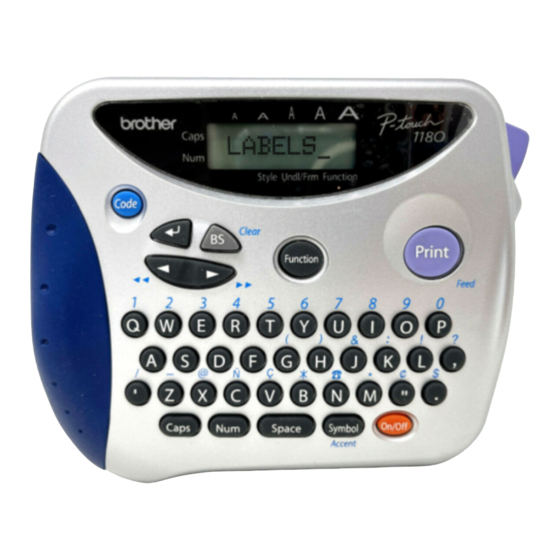
CHAPTER I SPECIFICATIONS MECHANICAL SPECIFICATIONS 1.1.1 External Appearance Fig. 1.1-1 External Appearance Dimensions (W x D x H) 154 x 129 x 60 mm (PT-1100/1130/1170/1180/11Q/ST-1150) 154 x 129 x 64 mm (PT-1250/1160) Weight Machine proper only Approx. 400 g In package Packaging Weight (g) Carton with One Unit... -
Page 8: Printing Mechanism
1.1.3 Display Display type Liquid crystal display (LCD) Number of columns 8 columns x 1 row (See Fig. 1.1-2.) Number of indicators 10 (See Fig. 1.1-2.) Character size 5 dots wide by 7 dots high Field-of-view angle Fixed by a resistor adjustment 1.1.4 Printing Mechanism... - Page 9 Fig. 1.1-2 Key Arrangement (1)
- Page 10 Fig. 1.1-2 Key Arrangement (2)
- Page 11 Fig. 1.1-2 Key Arrangement (3)
-
Page 12: Electronics Specifications
ELECTRONICS SPECIFICATIONS 1.2.1 Character Generator Internal characters U.K./ FRA/ BEL (PT-1250) GER (PT-1250) U.S.A./ CAN./AUS. (PT-1100/1130/1170/1180/11Q/ST-1150,and PT-1160/1250 for CAN.) Internal font HELSINKI Print buffer capacity 55 characters Phrase memory capacity 300 characters 1.2.2 Power Supply Power supply Driven by 6 batteries Optional AC adapter (7VDC, 1.2A) available * For PT-1180, the power supply is batteries only. - Page 13 CHAPTER II MECHANISMS...
- Page 14 CONTENTS CHAPTER II MECHANISM ................II-1 THEORY OF OPERATION ................... II-1 2.1.1 Print Mechanism .................... II-1 2.1.2 Platen Roller, (Tape Feed) Sub Roller Setting & Retracting Mechanism ..II-2 2.1.3 Tape & Ribbon Feed Mechanism..............II-3 2.1.4 Tape Cutter Mechanism ................. II-5 2.1.5 Cutter Safety Lock Mechanism...............
- Page 15 [ 8 ] Installing the tape cassette, the batteries, and the cassette cover ASSY..II-26 [ 9 ] Demonstration print and final check............. II-27 TROUBLESHOOTING ..................II-33 2.3.1 Precautions ....................II-33 2.3.2 After Repairing ....................II-33 2.3.3 Error Message Display ................... II-34 2.3.4 Troubleshooting Flows..................
-
Page 16: Chapter Ii Mechanism
CHAPTER II MECHANISM THEORY OF OPERATION 2.1.1 Print Mechanism Structure of Thermal Head This machine uses thermal transfer printing. The thermal print head has a heat generator consisting of 64 heating elements which are vertically aligned as shown in Fig. 2.1-1. Each heating element is 0.195 mm wide by 0.141 mm high. -
Page 17: Platen Roller, (Tape Feed) Sub Roller Setting & Retracting Mechanism
2.1.2 Platen Roller, (Tape Feed) Sub Roller Setting & Retracting Mechanism This mechanism consists of the holder cam (cassette cover ASSY) and the roller holder ASSY. The roller holder ASSY supports the platen roller and the sub roller so that : Ÿ... -
Page 18: Tape & Ribbon Feed Mechanism
2.1.3 Tape & Ribbon Feed Mechanism This mechanism consists of a DC motor, gear train, and roller holder ASSY. Tape Feeding As the tape feed motor (DC motor) rotates, the rotation is transmitted via the gear train to the platen idle gear (which rotates both the platen gear) and the tape idle gear (which rotates the tape feed sub roller). - Page 19 Adhesive Base Tape Feeding (only for laminated tape cassettes) A laminated tape cassette contains both a transparent laminate tape roll and a separate adhesive base tape roll. When a transparent laminate tape and an adhesive base tape pass through the contact point (between the tape feed roller and (tape feed) sub roller), they are then bonded together into a single, printed tape.
-
Page 20: Tape Cutter Mechanism
2.1.4 Tape Cutter Mechanism The tape cut unit consists from the cutter case ASSY and the board. Tape that finished printing is fed out from the tape cassette and stops at a point passed between the cutter case ASSY and the board. When the cutter lever is pushed at this point, then, the cutter case ASSY (cutter blade) is operated to cut tape. -
Page 21: Cutter Safety Lock Mechanism
2.1.5 Cutter Safety Lock Mechanism When the cassette cover ASSY is opened and no tape cassette is loaded, the roller holder ASSY is retracted from the thermal head with the roller holder release spring (as described in Subsection 2.1.2). In this retracted position, the cutter lever stopper of the roller holder ASSY blocks the end of the cutter lever, preventing the cutter blade from coming out of the cutter case ASSY for safety, as shown below. -
Page 22: Interlock Mechanism Of The Roller Holder
2.1.6 Interlock Mechanism of the Roller Holder When the cassette case ASSY is opened, then the holder cam attached at back side of cassette cover is released from surface A. Following to that, the roller holder ASSY is retracted from the thermal head side with tension of the roller release spring. When the cassette cover ASSY is closed, then the holder cam located at backside pushes the thermal head at roller holder ASSY by pressing A surface of the roller holder ASSY. -
Page 23: Disassembly & Reassembly
PT2002008 DISASSEMBLY & REASSEMBLY 2.2.1 Disassembly Procedure [ 1 ] Removing the cassette cover ASSY, the tape cassette and the batteries Turn the machine upside down. Open the cassette cover ASSY by applying the force toward “A” direction. Push the rib “B” on the holder cam assembled on the cassette cover ASSY to the direction of the arrow to remove the holder cam from the cassette cover ASSY. -
Page 24: 2 ] Removing The Bottom Cover, The Cutter Case Assy And The Board
[ 2 ] Removing the bottom cover, the cutter case ASSY and the board Place the machine upside down. Pull out the cutter case ASSY and the board from the frame. Remove the four screws, then the bottom cover and the upper cover are able to be separated. -
Page 25: 3 ] Removing The Frame Assy
[ 3 ] Removing the frame ASSY Remove the two motor harnesses from the sub PCB by melting the solder. Remove the three screws and remove the frame ASSY from the bottom cover. Note: The cutter lever will be disconnected from the cutter lever shaft of the frame Assy at this point. - Page 26 Disassembling the Frame ASSY Removing the DC motor ASSY Remove the two screws from the frame ASSY and take out the motor ASSY. DC motor ASSY Frame ASSY Screws Fig. 2.2-6 Removing the DC Motor ASSY II-11...
- Page 27 Removing the roller holder ASSY and thermal head ASSY When handling the thermal head ASSY, do not touch the thermal head by hand. Otherwise, it may be damaged due to the electricity charged in your body. After taking off the retaining ring, remove the roller holder ASSY and the roller holder return spring from the frame ASSY.
-
Page 28: Removing The Terminal Press Cover
[ 4 ] Removing the terminal press cover Remove the terminal press cover by releasing the hooks from the grooves of the bottom cover. You can remove the terminal press cover by releasing the two hooks from the back side of the bottom cover by using tool like a flat screwdriver. -
Page 29: 5 ] Removing The Battery Terminals
[ 5 ] Removing the battery terminals Remove the battery terminal B (+,-) from the bottom cover. After disengaging the hook of the battery terminal (+) by tool like a flat screwdriver, remove the battery terminal (+) from the bottom cover. Battery terminal B (+,-) Battery terminal (+) Battery terminal (+) -
Page 30: Removing The Sub Pcb
[ 6 ] Removing the sub PCB After removing the battery terminal (+), the battery terminal (-), take off a screw and remove the sub PCB. Note: The AC jack is not provided on the sub PCB for PT-1180. Therefore the form of the bottom cover is slightly different from the figure below. -
Page 31: Removing The Main Pcb And The Rubber 41 Key (Pt-1100/1130/1170/1180/11Q/St-1150
[ 7 ] Removing the main PCB and the rubber 41 key (PT-1100/1130/1170/S1180/11QI-1150) Remove the four screws, then take off the main PCB and the rubber 41 key. Note1: Before handling the main PCB, touch a metal portion of the machine to discharge static electricity, or the LSI and other electronic devices should be damaged due to the electricity charged in your body. -
Page 32: 8 ] Removing The Main Pcb, The Rubber 40 Key And The Jog Dial (Pt-1250/1160
[ 8 ] Removing the main PCB, the rubber 40 key and the jog dial (PT-1250/1160) Remove the four screws, then take off the main PCB, the rubber 40 key and the jog dial. Note1: Before handling the main PCB, touch a metal portion of the machine to discharge static electricity, or the LSI and other electronic devices should be damaged due to the electricity charged in your body. -
Page 33: Reassembly Procedure
2.2.2 Reassembly Procedure [ 1 ] Installing the rubber 41 key and main PCB (PT-1100/1130/1170/1180/11Q/ST-1150) Turn the upper cover upside down and place the rubber 41 key so that it is fitted into the nine boss provided on the upper cover. Check that there is no foreign material or dust on the key contacts of the main PCB, then install the PCB. -
Page 34: 2 ] Installing The Jog Dial, The Rubber 40 Key And The Main Pcb (Pt-1250/1160
[ 2 ] Installing the jog dial, the rubber 40 key and the main PCB (PT-1250/1160) Turn the upper cover upside down and place the rubber 40 key so that it is fitted into the seven bosses provided on the upper cover. The jog dial set on the upper cover. -
Page 35: 3 ] Installing The Sub Pcb
[ 3 ] Installing the sub PCB Relay harness is solder connected to the sub PCB. After pushing the “A” section of battery terminal (+) of sub PCB ASSY, perform the wiring. (Refer to Fig. 2.2-20) Set the sub PCB into the locating pin and AC jack groove, and tighten the screw, confirming that each of the sensor switch actuators is fitted into the hole of the bottom cover certainly and moves up and down freely. -
Page 36: 4 ] Installing The Battery Terminals
[ 4 ] Installing the battery terminals Put three battery terminals A (+,-) into the bottom cover from the direction of arrow. Turn the bottom cover upside down and fit the battery terminal (+) of the battery harness ASSY into the bottom cover. Put two battery terminals B (+,-) into the bottom cover from the same direction. -
Page 37: 6 ] Installing The Frame Assy
[ 6 ] Installing the frame ASSY Install the cutter lever into the bottom cover. If the frame ASSY has been disassembled, assemble the components by referring to the next page. The frame ASSY is set by matching the locating pin and the locating boss of the bottom cover. - Page 38 Assembling the components of the motor holder ASSY Installing the thermal head ASSY and the roller holder ASSY Install the thermal head to the frame ASSY, and tighten the screw. Tightening torque: 0.59 N . m (6 kg . cm) Screw Thermal head ASSY Frame ASSY...
- Page 39 Installing the DC motor ASSY Tighten the DC motor to the frame ASSY with the two screws. Be careful to the direction of the motor harnesses. 0.20 N . m (1 2 kg . cm) Tightening torque: 0.10 Backlash of DC motor = 0.05 0.2 mm DC motor ASSY Screws...
-
Page 40: 7 ] Installing The Cutter Case Assy, Board And The Bottom Cover
[ 7 ] Installing the cutter case ASSY, board and the bottom cover Hold the bottom cover as shown below, then connect the thermal head flat cable to the main PCB through under the motor harness and the power supply harness connector. Upper cover Thermal head flat cable Bottom cover... -
Page 41: 8 ] Installing The Tape Cassette, The Batteries, And The Cassette Cover Assy
PT2002008 [ 8 ] Installing the tape cassette, the batteries, and the cassette cover ASSY Hook “A” of the cassette cover is set at the boss of bottom cover. The cassette is installed, thereafter, at the “B” section by applying a force (sliding torque) toward “C”. Cassette cover ASSY “A”... -
Page 42: 9 ] Demonstration Print And Final Check
[ 9 ] Demonstration Print and Final Check Following items are verified lastly after completed the assembly. Press the “On/Off ( )” key. While holding down the “Code” key, press the “BS ( )” key to cancel data previously entered. Return the “Caps”, “Size”, “Style”, “UNDL/FRM”, “Function”, and “NUMBER”... - Page 43 9.2.1.1. Country Display The country display displays the country specifications as designated by the solder points (1 ~ 3.) [UK, GER, FRE, BEL, USA/CAN/AUS] MODEL Country Solder Specification Specification Points Display PT-1100/1130/1170 USA/CAN/AUS /1180/11Q/ST-1150 PT-1250/1160 CANADA PT-1250 French Belgium German (“L”...
- Page 44 9.2.1.4. LCD Check Display Here, check for missing dots and the display function of the LCD. The LCD check 1 <Fig. 4> is displayed when depressed “ ” key. All guidance off. H H H H H H H H All cursor off.
- Page 45 Fig. 10 Fig. 11 When all key checks were completed, then displays Fig. 12 and cut the tape by printing <<OK>>. Fig. 12 Shifts to “9.2.4 CUT Mode” when depressed “ ” key. (Fig. 14 Display) * PT-1250/1160, however, shifts to the “JOG Dial Check Mode”. Enters into the JOG Dial Check Mode after printed that all key had been completed without displaying OK.
- Page 46 Fig. 17 is displayed when depressed “ ” key to feed the tape. “3” is displayed after completed the feed. F E E D Fig. 17 Shifts to “28.2.5 PRINT 1 Mode” when depressed “ ” key. (Fig. 18 Display) 9.2.5.
- Page 47 9.2.7. MOTOR Mode “7” Key: Used for the DC motor speed adjustment. This mode is used only when the print length accuracy or tape feed length accuracy deviates from the specification. Display of Fig. 20 is indicated when depressed “7” key. M T R Fig.
-
Page 48: Troubleshooting
TROUBLESHOOTING This section gives the service personnel some of the troubleshooting procedures to be followed if an error or malfunction occurs with the PT-1100/1130/1170/1180/11Q, PT-1250/1160 and ST- 1150. It is impossible to anticipate all of the possible troubles which may occur in future and determine the troubleshooting procedures, so this chapter covers some sample troubles. -
Page 49: Error Message Display
2.3.3 Error Message Display Error is displayed when the troubles as shown below happen.“ERROR” display for each country will be displayed as follows. U.S.A./U.K./BELGIUM: ERROR FRENCH/CANADA: ERREUR GERMAN: FEHLER Input Mode Error Conditions Remarks Text Input Mode “SET ( )” key depressed when exceeded 2. -
Page 50: Troubleshooting Flows
2.3.4 Troubleshooting Flows [ 1 ] Tape feeding failure... -
Page 52: 2 ] Printing Failure
[ 2 ] Printing failure... -
Page 54: 3 ] Powering Failure (Nothing Appears On The Lcd
[ 3 ] Powering failure (Nothing appears on the LCD) -
Page 55: 4 ] No Key Entry Possible
[ 4 ] No key entry possible... - Page 56 CHAPTER III ELECTRONICS...
- Page 57 CONTENTS CHAPTER III ELECTRONICS ................III-1 OVERVIEW ......................III-1 3.1.1 Configuration of the Electronic Part ..............III-1 3.1.2 Main PCB....................... III-1 3.1.3 Sub PCB ......................III-1 3.1.4 Motor......................III-1 3.1.5 Thermal Head ....................III-1 MAIN PCB......................III-2 3.2.1 Main PCB Block Diagram ................III-2 3.2.2 CPU and LCD Driver ..................
- Page 58 TROUBLESHOOTING ..................III-16 3.3.1 Precautions ....................III-16 3.3.2 After Repairing ....................III-16 3.3.3 Troubleshooting Flows..................III-17 [ 1 ] Tape feeding failure..................III-17 [ 2 ] Printing failure ..................... III-17 [ 3 ] Powering failure (Nothing appears on the LCD.) .......... III-18 [ 4 ] Abnormal LCD indication................
-
Page 59: Chapter Iii Electronics
CHAPTER III ELECTRONICS OVERVIEW 3.1.1 Configuration of the Electronic Part Fig. 3.1-1 shows a block diagram of the control electronics of the PT-1100/1130/1170/1180/11Q, PT-1250/1160 and ST-1150. The control electronics consists of a printed circuit board (main PCB + Sub PCB), a motor, and a thermal head assembly. 3.1.2 Main PCB This manages all the components including an LCD, keyboard, (Jog dial :PT-1250/1160 only) and... -
Page 60: Main Pcb
MAIN PCB 3.2.1 Main PCB Block Diagram Fig. 3.2-1 shows the Main PCB block diagram. The PCB consists of the following: CPU (including a ROM, RAM, and LCD control) Key contacts matrix, solder points (specification switching-over circuit) and jog dial (PT- 1250/1160 only). -
Page 61: Cpu And Lcd Driver
3.2.2 CPU and LCD Driver The CPU (MU101C30A) is a 8bit microprocessor produced by CMOS silicon gate process, which integrates a 32 kilobyte-ROM and a 1.5 kilobyte-RAM. The LCD driver (SPLC 780 A2) is a LSI that drives the LCD in 1/8 duty and 1/4 bias level. Fig. -
Page 62: Key Contacts Matrix
3.2.3 Key Contacts Matrix [ 1 ] Key contacts matrix On the main PCB is a key contacts matrix that is a set of carbon-printed 41 key (PT-1250/1160: 40 key + tact switch) contact patterns. Each contact pattern has a pair of electrodes. The rubber 42 key (PT-1250/1160: 41 key) is made of high-impedance silicon rubber. -
Page 63: 2 ] Solder Points
[ 2 ] Solder points Fig. 3.2-5 shows a circuit diagram relating to the keyboard and solder points. Solder points 1 through 4 are connected to satisfy the specification of PT-1100/1130/1170/1180/11Q, PT- 1250/1160 and ST-1150. Specification PT-1250 PT-1160 PT-1100/1130/1170/1180 11Q/ST-1150 Solder point MN101C30ABE MN101C30ABF1... -
Page 64: 3 ] Jog Dial (Only For Pt-1250/1160)
[ 3 ] Jog dial (Only for PT-1250/1160) The two input signal (JOG0, JOG1) waveforms are varied by rotating the JOG dial. The rotational directions are determined from the variation pattern of this two input signal waveforms. <JOG Switching Dial Signal> (CW) JOG0 signal JOG1 signal... -
Page 65: On/Off Key/Reset Circuit And Power Saving Circuit
3.2.4 On/Off Key/Reset Circuit and Power Saving Circuit [ 1 ] Power On/Off circuit Fig. 3.2-8 shows a circuit diagram of the power On/Off key. The CPU processes the On/Off key state in a sequence quite different from other keys although the On/Off key is on the same key pad. -
Page 66: 2 ] Power Saving Circuit
[ 2 ] Power saving circuit Fig. 3.2-10 shows a circuit diagram of the power saving circuit. If you power off the machine with the power On/Off key or you make no key entry for approx. 5 minutes, the CPU turns P11 high to cut off the Vcc (which normally would feed power to the logic circuits except the CPU). -
Page 67: Motor Control Circuit
3.2.5 Motor Control Circuit Fig. 3.2-11 shows the motor drive control of the DC motor which feeds tape. Through P10, the CPU produces a start/stop control signal to the motor control circuit. Fig. 3.2-12 shows the part of motor waveforms. #1 (BA6220) is electronic governor IC and controls to keep the rotation speed of motor constant even if the power source voltage (VBT) varies. -
Page 68: Thermal Head Drive Circuit
3.2.6 Thermal Head Drive Circuit Fig. 3.2-13 shows the thermal head drive circuit. The print head used in the integrates a heat generator (consisting of 64 heating elements vertically aligned in 180 dpi) and a built-in driver IC. Synchronizing with the clock on P02, the CPU outputs print data on P00 in the serial waveform. Upon receipt of P01 signal produced by the CPU, the thermal head control circuit latches the print data and drivers the heating elements of the thermal head according to the signal produced from P03. -
Page 69: Voltage Detection Circuit And Temperature Sensor Circuit
3.2.7 Voltage Detection Circuit and Temperature Sensor circuit Fig. 3.2-15 and Fig. 3.2-16 (See next page) show the voltage detection circuit and the ambient sensor circuit which are composed of a resister combination. [ 1 ] Voltage detection circuit This circuit, which is composed of divider resistors R8 and R10, steps down the power source VAD fed from batteries or the AC adapter output and feeds the output to the A/D input port PA1 on the CPU. -
Page 70: 2 ] Ambient Temperature Sensor Circuit
[ 2 ] Ambient temperature sensor circuit This circuit is composed of resistors R12 and a thermistor TH2. It converts the resistance of the TH2 (whose internal resistance varies depending upon the ambient temperature) to the voltage variation, and then feeds its output to the A/D input port PA0 on the CPU. According to the Ambient temperature data, the CPU determines the optimum head drive power. -
Page 71: Oscillation Circuit
3.2.8 Oscillation Circuit Fig. 3.2-17 shows the oscillation circuit. This circuit contains an oscillator and generates an oscillation at 8 MHz which act as the CPU basic clock. The CPU divides this into half (4 MHz) to synchronize its internal operations. Fig. -
Page 72: Power Supply Circuit
3.2.9 Power Supply Circuit Fig. 3.2-18 shows the power supply circuit. A 3-terminal regulator RH5RL50A stabilizes the battery output or the AC adapter output, producing the +5BV power source within the variation of ±0.15V. Capacitor C4 is for the logic circuit; capacitor C1 is for the thermal head and DC motor drive sources. -
Page 73: 3.2.10 Cassette Sensor Circuit
3.2.10 Cassette Sensor Circuit Fig. 3.2-20 shows the cassette sensor circuit. This circuit detects each of the five sensor switches which is pushed or not depending upon the ID holes provided on a tape cassette currently mounted. By perceiving the states of those sensor switches, the CPU identifies the tape cassette type (the varieties and the widths). -
Page 74: Troubleshooting
TROUBLESHOOTING This section gives the service personnel some of the troubleshooting procedures to be followed if an error or malfunction occurs with the PT-1100/1130/1170/1180/11Q, PT-1250/1160 and ST- 1150. It is impossible to anticipate all of the possible troubles which may occur in future and determine the troubleshooting procedures, so this chapter covers some sample troubles. -
Page 75: Troubleshooting Flows
3.3.3 Troubleshooting Flows [ 1 ] Tape feeding failure [ 2 ] Printing failure III-17... -
Page 76: 3 ] Powering Failure (Nothing Appears On The Lcd.)
[ 3 ] Powering failure (Nothing appears on the LCD.) III-18... -
Page 77: 4 ] Abnormal Lcd Indication
[ 4 ] Abnormal LCD indication III-19... -
Page 78: 5 ] No Key Entry Possible
[ 5 ] No key entry possible [ 6 ] Tape cassette type not identified III-20... - Page 79 APPENDICES Circuit Diagrams A: MAIN PCB CIR 1100 (PT-1100/1130/1170/1180/11Q/ST-1150) B: MAIN PCB CIR 1250 (PT-1250/1160) C: SUB PCB CIR 1250...
- Page 83 Jan., 2002 8V2010BE1 Printed in Japan...
Need help?
Do you have a question about the P-touch PT-1180 and is the answer not in the manual?
Questions and answers