Fluke 187 User Manual
True rms multimeter
Hide thumbs
Also See for 187:
- Calibration manual (38 pages) ,
- Getting started (32 pages) ,
- Extended specifications (3 pages)

Related Manuals for Fluke 187


Summary of Contents for Fluke 187
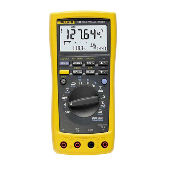
- Page 1 ® Model 187 & 189 True RMS Multimeter Users Manual August 2000, Rev.2, 6/02 © 2000, 2002 Fluke Corporation. All rights reserved. Printed in U.S.A. All product names are trademarks of their respective companies.
- Page 2 Lifetime Limited Warranty Each Fluke 20, 70, 80, 170 and 180 Series DMM will be free from defects in material and workmanship for its lifetime. As used herein, “lifetime” is defined as seven years after Fluke discontinues manufacturing the product, but the warranty period shall be at least ten years from the date of purchase.
-
Page 3: Table Of Contents
Table of Contents Chapter Title Page Before You Start ......................1-1 Safety Information......................1-1 Contacting Fluke......................1-1 Symbols ......................... 1-4 Getting Acquainted...................... 2-1 Introduction........................2-1 Turning the Meter On..................... 2-1 Battery Considerations ....................2-2 Automatic Power Off ....................2-2 Automatic Backlight Off..................... 2-3 Low Battery Indication.................... - Page 4 Model 187 & 189 Users Manual Selecting the Range....................... 2-10 Understanding the Display ..................... 2-10 Primary Display ......................2-10 Secondary Display..................... 2-11 Bar Graph........................2-11 Using the Input Terminals ....................2-17 Using Display Hold ......................2-18 Using AutoHOLD......................2-19 Using MIN MAX......................2-19 Using FAST MN MX .......................
- Page 5 Contents (continued) Measuring AC Current ....................3-18 Measuring DC Current ....................3-20 Measuring Frequency ....................3-22 Measuring Duty Cycle....................3-23 Measuring Pulse Width....................3-25 Using Memory & Communications Features ............4-1 Introduction........................4-1 Types of Memory ......................4-1 Saved Readings Memory..................4-1 Logged Readings Memory..................
- Page 6 Model 187 & 189 Users Manual Maintenance ......................... 6-1 Introduction ........................6-1 General Maintenance..................... 6-1 Testing the Fuses......................6-1 Replacing the Batteries ....................6-3 Replacing the Fuses ...................... 6-5 User-Replaceable Parts ....................6-5 In Case of Difficulty ......................6-5 Specifications....................... 7-1 Safety and Compliances ....................
- Page 7 List of Tables Table Title Page 1-1. Safety Information......................... 1-2 1-2. International Electrical Symbols.................... 1-4 2-1. Rotary Switch Selections ...................... 2-6 2-2. Pushbuttons.......................... 2-8 2-3. Display Features ........................2-13 3-1. Current Measurement ......................3-16 4-1. View Display ......................... 4-4 5-1. Function Specific Setup Selections..................5-2 5-2.
-
Page 8: Model
Model 187 & 189 Users Manual... - Page 9 List of Figures Figure Title Page 2-1. AC Volts Display ........................2-2 2-2. Rotary Switch........................2-4 2-3. Pushbuttons.......................... 2-5 2-4. Display Features ........................2-12 2-5. Input Terminals ........................2-17 2-6. Display Hold and AutoHOLD ....................2-18 2-7. Min Max Avg ......................... 2-21 2-8.
- Page 10 Model 187 & 189 Users Manual 3-10. Temperature Measurement ....................3-15 3-11. AC Current Measurement...................... 3-19 3-12. DC Current Measurement ..................... 3-21 3-13. Functions Allowing Frequency Measurement................ 3-22 3-14. Hz Display ..........................3-23 3-15. Duty Cycle Measurements ....................3-24 3-16. Duty Cycle Display ........................ 3-25 3-17.
-
Page 11: Before You Start
Chapter 1 Before You Start Safety Information Contacting Fluke The Fluke Model 187 and Model 189 True RMS To order accessories, receive assistance, or locate the Multimeters (hereafter referred to as the “meter”) comply nearest Fluke distributor or Service Center, call:... -
Page 12: Safety Information
Model 187 & 189 Users Manual Table 1-1. Safety Information WWarning To avoid possible electric shock or personal injury, follow these guidelines: Do not use the meter if it is damaged. Before you use the meter, inspect the case. Look for cracks or missing plastic. - Page 13 Before You Start Safety Information Table 1-1. Safety Information (cont.) WWarning When using the probes, keep your fingers behind the finger guards on the probes. Connect the common test lead before you connect the live test lead. When you disconnect test leads, disconnect the live test lead first.
-
Page 14: Symbols
Model 187 & 189 Users Manual Symbols Symbols used on the meter and in this manual are explained in Table 1-2. Table 1-2. International Electrical Symbols AC (Alternating Current) Earth ground DC (Direct Current) Fuse AC and DC Double insulated Battery Important information Complies with relevant Canadian... -
Page 15: Getting Acquainted
Chapter 2 Getting Acquainted Introduction Turning the Meter On Although this manual describes the operation of both To turn the meter on, turn the rotary switch from OFF to Models 187 and 189, all illustrations and examples any switch setting. assume use of Model 189. -
Page 16: Battery Considerations
Model 187 & 189 Users Manual Automatic Power Off The display blanks and the meter goes into a “sleep” mode if you have not changed the rotary switch position or pressed a button for a set period. While in Sleep mode, pressing any button turns the meter on. -
Page 17: Automatic Backlight Off
Getting Acquainted Battery Considerations Automatic Backlight Off Low Battery Indication Press to select the backlight level (low, high, or off.) In A constant battery icon ( ) in the upper left corner of low or high, the backlight turns off automatically after a the display notifies you that the batteries are low and given period. -
Page 18: Rotary Switch
Model 187 & 189 Users Manual The rotary switch is shown in Figure 2-2. Each position is Rotary Switch described in Table 2-1. Turn the meter on by selecting any measurement function (identified with white letters around the rotary switch). The meter presents a standard display for that function (range, measurement units, modifiers, etc.) The display may also be influenced by some of the choices made in Setup. -
Page 19: Pushbuttons
Getting Acquainted Pushbuttons Pushbuttons The buttons activate features that augment the function LOGGING AutoHOLD FAST MN MX selected with the rotary switch. The buttons are shown in HOLD HOLD MIN MAX MIN MAX Figure 2-3 and described in Table 2-2. CANCEL SAVE Use the blue button (... -
Page 20: Rotary Switch Selections
Model 187 & 189 Users Manual Table 2-1. Rotary Switch Selections Position Rotary Switch Function Blue Key Function AC voltage measurement from 0 V to 1000.0 V dB over AC, AC over dB AC millivolt measurement from 0 mV to 3000.0 mV dB over AC, AC over dB DC voltage measurement from 0 V to 1000.0 V AC over DC (AC in primary display, DC in secondary... - Page 21 Getting Acquainted Pushbuttons Table 2-1. Rotary Switch Positions (cont.) Position Rotary Switch Function Blue Key Function AC current measurements from 0 mA to 20.000 A none AC current measurements from 0 A to 5000.0 A none DC current measurements from 0 mA to 20.000 A AC over DC (AC in primary display, DC in secondary display), DC over AC, ac+dc DC current measurements from 0 A to 5000.0 A...
-
Page 22: Pushbuttons
Model 187 & 189 Users Manual Table 2-2. Pushbuttons Yellow Button Button Description Function Description Note Press to access “Yellow Button Functions.” The box and the 24-hour clock appear in the lower corners of the display and the primary display freezes, allowing time to press a second button. Press to turn backlight on or off. - Page 23 Getting Acquainted Pushbuttons Table 2-2. Pushbuttons (cont.) Yellow Button Button Description Function Description In Setup, increment a digit . (none) In counter functions, select positive pulse slope. In ohms continuity, select beep on open. In VIEW MEM, see Chapter 4 (Model 189). In Setup, decrement a digit .
-
Page 24: Selecting The Range
Model 187 & 189 Users Manual Selecting the Range Understanding the Display Press to select either a fixed range or the Display features are shown in Figure 2-4 and described in autorange feature. Table 2-3. Major display features are described in the following paragraphs. -
Page 25: Secondary Display
Getting Acquainted Understanding the Display dB (in ac volts functions): the dBm or dBV value. Bar Graph The bar graph provides an analog indication of the REL: the difference between the present reading and measured input. For most measurement functions, the bar a stored reference reading. - Page 26 Model 187 & 189 Users Manual tc011f.eps Figure 2-4. Display Features 2-12...
-
Page 27: Display Features
Getting Acquainted Understanding the Display Table 2-3. Display Features Number Feature Description Continuity test function is selected. Bar Graph. In normal operation 0 (zero) is on the left. In Relative %, 0 is in the center, negative values are to the left and positive to the right. The polarity indicator left of the bar graph shows the polarity of the input. - Page 28 Model 187 & 189 Users Manual Table 2-3. Display Features (cont.) Number Feature Description FAST FAST MN MX mode is enabled. ( Minimum reading displayed. Maximum reading displayed. Average reading displayed. Readings are being recorded in memory (Model 189 only.) ( The meter is in Hold mode.
- Page 29 Getting Acquainted Understanding the Display Table 2-3. Display Features (cont.) Number Feature Description AC+DC For dc volts and dc amps functions, reading represents the rms total of ac and dc measurements. e, ke Me, : Ohm. The unit of resistance. k : Kilohm.
- Page 30 Model 187 & 189 Users Manual Table 2-3. Display Features (cont.) Number Feature Description 51000 Range. Digits display range in use. MANUAL AUTO Time Display. Used with HOLD, AutoHOLD, MIN MAX, FAST MN MX (SAVE, and LOGGING Model 189). Elapsed Time Display ( on): shown in minutes:seconds to maximum of 59:59 - used if time since Min, Max, or Logging started is less than 60 minutes.
-
Page 31: Using The Input Terminals
Getting Acquainted Using the Input Terminals Using the Input Terminals All functions except current use the inputs. Current functions use the inputs shown below: function: Use A and COM inputs from 400 mA to 20 A. Use mA/ A and COM for inputs function: Use mA/ A and COM for inputs 5000.0 A. -
Page 32: Using Display Hold
Model 187 & 189 Users Manual Using Display Hold AutoHOLD Press to enter the Display Hold mode and freeze the present reading and its time stamp. New readings now appear in the secondary display. See Figure 2-6. To exit Display Hold mode, press again. -
Page 33: Using Autohold
Getting Acquainted Using AutoHOLD Using AutoHOLD Using MIN MAX WWarning The MIN MAX mode stores minimum (MIN) and maximum (MAX) input values. When the input goes below the stored AutoHOLD mode does not capture unstable minimum value or above the stored maximum value, the or noisy readings. - Page 34 Model 187 & 189 Users Manual To exit MIN MAX mode, press (CANCEL) or turn the rotary switch to a different position. Also, MIN MAX mode turns off automatically when a flashing (low battery condition) occurs. Note Minimum, maximum, and average values stored in the MIN MAX mode are lost when the meter is turned off.
-
Page 35: Using Fast Mn Mx
Getting Acquainted Using FAST MN MX Using FAST MN MX FAST MN MX can capture transient signal events as short as 250 µs, but with decreased accuracy; only 3-1/2 display digits are allowed. Activate FAST MN MX by pressing . As with regular MIN MAX, you can then press to cycle through maximum, minimum, and average primary... -
Page 36: Using Hold With Min Max Or Fast Mn Mx
Model 187 & 189 Users Manual Using HOLD with MIN MAX or FAST MN MX Press a second time to enter the REL% mode and display the difference as 10 % of the reference You can enable the HOLD mode when in the MIN MAX reading. -
Page 37: Making Measurements
5.0000 V range to provide direct reading display for volts or amps position. Fluke accessories that have a millivolt output with limits scaled by 1000. For example, the Fluke 80i-1000 Measuring Voltage Current Clamp provides 1 mV ac per amp measured up to 1000 amps. -
Page 38: Measuring Ac Voltage
Model 187 & 189 Users Manual When measuring voltage, the meter acts like a 10 M (10,000,000 ) impedance in parallel with the circuit. This loading effect can cause measurement errors in high- impedance circuits. In most cases, the error is negligible (0.1% or less) if the circuit impedance is 10 k (10,000 or less. -
Page 39: Db Measurements In Ac Volts Functions
Making Measurements Measuring Voltage dB Measurements in AC Volts Functions The two ac volts functions allow you to display readings as deviations in dB (decibels) above or below an established level. Set up dB measurements with the following procedure: Make an ac volts measurement to be used as a reference point. -
Page 40: Both Ac And Dc Voltage Measurements
Model 187 & 189 Users Manual dB is calculated with the following formula: Measuring DC Voltage Set up the meter for dc voltage measurement as shown in Figure 3-4. All pushbutton features are available for a standard dc volts reading. Both AC and DC Voltage Measurements For dBm, Vr is the voltage across the reference resistance at 1 mW. - Page 41 Making Measurements Measuring Voltage AC over DC DC over AC AC + DC tc024f.eps Figure 3-3. AC and DC Display When the meter shows ac over dc or dc over ac, the following other pushbutton functions are not available: AutoHOLD ( MIN MAX ( FAST MN MX ( Hz (...
-
Page 42: Measuring Resistance
Model 187 & 189 Users Manual Measuring Resistance Caution LOGGING MULTIMETER To avoid possible damage to the meter or to the equipment under test, disconnect circuit power and discharge all high-voltage capacitors before measuring resistance. AutoHOLD FAST MN MX LOGGING HOLD HOLD MIN MAX... - Page 43 Making Measurements Measuring Resistance In-Circuit Resistance Measurements Isolating a Potentiometer Circuit Power LOGGING MULTIMETER Disconnect LOGGING AutoHOLD FAST MN MX HOLD HOLD MIN MAX MIN MAX CANCEL SAVE RANGE RANGE Isolating a Resistor SETUP ac+dc ac+dc ac+dc ac+dc ac+dc ac+dc ac+dc ac+dc VIEW...
-
Page 44: Testing For Continuity
Model 187 & 189 Users Manual Testing for Continuity Keep the following in mind when measuring resistance: Caution Because the meter’s test current flows through all possible paths between the probe tips, the measured To avoid possible damage to the meter or to value of a resistor in a circuit is often different from the equipment under test, disconnect circuit the resistor’s rated value. -
Page 45: Using Conductance For High Resistance Tests
Making Measurements Using Conductance for High Resistance Tests Continuity testing provides you with both a visual Using Conductance for High Resistance indication of the state encountered (usually near 0 Tests resistance for a short or OL for an open) and an audible beep when the input is low. - Page 46 Model 187 & 189 Users Manual For in-circuit tests, turn circuit power off. Press for beep on open LOGGING MULTIMETER LOGGING MULTIMETER Press for beep on short LOGGING AutoHOLD FAST MN MX LOGGING AutoHOLD FAST MN MX HOLD HOLD MIN MAX MIN MAX HOLD HOLD...
- Page 47 Making Measurements Using Conductance for High Resistance Tests The following are some tips for measuring conductance: High-resistance readings are susceptible to electrical noise. Use averaging to smooth out most noisy readings; press until AVG appears in the display. LOGGING MULTIMETER There is normally a residual conductance reading with the test leads open.
-
Page 48: Measuring Capacitance
Model 187 & 189 Users Manual To measure capacitance, set up the meter as shown in Measuring Capacitance Figure 3-8. The blue key toggles the selection between Caution capacitance and diode test. To avoid possible damage to the meter or to While measuring capacitance, the following pushbutton the equipment under test, disconnect circuit functions are not available:... -
Page 49: Testing Diodes
Making Measurements Testing Diodes Testing Diodes Caution LOGGING MULTIMETER To avoid possible damage to the meter or to the equipment under test, disconnect circuit power and discharge all high-voltage capacitors before testing diodes. AutoHOLD FAST MN MX LOGGING HOLD HOLD MIN MAX MIN MAX CANCEL... - Page 50 Model 187 & 189 Users Manual Typical Reading LOGGING MULTIMETER LOGGING MULTIMETER AutoHOLD FAST MN MX LOGGING AutoHOLD FAST MN MX LOGGING HOLD HOLD MIN MAX MIN MAX HOLD HOLD MIN MAX MIN MAX CANCEL SAVE CANCEL SAVE RANGE RANGE RANGE RANGE SETUP...
-
Page 51: Measuring Temperature
Making Measurements Measuring Temperature Measuring Temperature To measure temperature, set up the meter as shown in LOGGING MULTIMETER Figure 3-10. The meter begins temperature measurement in the degree units last used (Celsius C or Fahrenheit F). Once you have selected the temperature function, you can change units by pressing the blue button. -
Page 52: Measuring Current
Model 187 & 189 Users Manual To measure ac or dc current, proceed as follows: Measuring Current WWarning Turn off power to the circuit. Discharge all high- voltage capacitors. Never attempt an in-circuit current Insert the black lead into the COM terminal. Insert the measurement where the open-circuit potential red lead in an input appropriate for the measurement to earth is greater than 1000 V. -
Page 53: Input Alert™ Feature
Making Measurements Measuring Current If you are using the A terminal, set the rotary switch to Input Alert™ Feature mA/A. If you are using the mA/ A terminal, set the If a test lead is plugged into the mA/ A or A terminal, but rotary switch to A for currents below 5000 A the rotary switch is not correctly set to one of the current (5 mA), or mA/A for currents above 5000 A. -
Page 54: Measuring Ac Current
Model 187 & 189 Users Manual The following are some tips for measuring current: Measuring AC Current To measure ac current, set up the meter as shown in If the display shows and you are sure the Figure 3-11. meter is set up correctly, test the meter’s fuses as described under "Testing the Fuses"... - Page 55 Making Measurements Measuring Current LOGGING MULTIMETER LOGGING MULTIMETER LOGGING MULTIMETER AutoHOLD FAST MN MX LOGGING AutoHOLD FAST MN MX LOGGING AutoHOLD FAST MN MX LOGGING HOLD HOLD MIN MAX MIN MAX HOLD HOLD MIN MAX MIN MAX HOLD HOLD MIN MAX MIN MAX CANCEL SAVE...
-
Page 56: Measuring Dc Current
Model 187 & 189 Users Manual Press a third time to display the ac + dc rms value Measuring DC Current in the primary display. (FAST MN MX is unavailable in To measure dc current, set up the meter as shown in this state.) Figure 3-12. - Page 57 Making Measurements Measuring Current Total current to circuit Circuit Power: OFF to connect meter. ON for measurement. OFF to disconnect meter. LOGGING MULTIMETER AutoHOLD FAST MN MX LOGGING HOLD HOLD MIN MAX MIN MAX CANCEL SAVE RANGE RANGE Current through one component SETUP ac+dc ac+dc...
-
Page 58: Measuring Frequency
Model 187 & 189 Users Manual Measuring Frequency Frequency is the number of cycles a signal completes each second. The meter measures the frequency of a voltage or current signal by counting the number of times ac+dc the signal crosses a threshold level each second. Figure 3-13 highlights the function selections that allow ac+dc frequency measurement. -
Page 59: Measuring Duty Cycle
Making Measurements Measuring Duty Cycle The following are some tips for measuring frequency: If a reading shows as 0 Hz or is unstable, the input signal may be below or near the trigger level. You can usually correct these problems by selecting a lower range, which increases the sensitivity of the meter. - Page 60 Model 187 & 189 Users Manual Measures Positive Pulse +Slope -Slope Trigger Point Trigger Point 30% Above Trigger Point 100% Measures Negative Pulse -Slope +Slope Trigger Point Trigger Point 70% Below Trigger Point 100% tc009f.eps Figure 3-15. Duty Cycle Measurements 3-24...
-
Page 61: Measuring Pulse Width
Making Measurements Measuring Pulse Width input range will often measure better than the AUTO- To measure duty cycle, set up the meter to measure selected input range. frequency; then press a second time. You can select the level the meter uses by pressing If a duty cycle reading is unstable, press until the trigger on the positive slope or... - Page 62 Model 187 & 189 Users Manual Start and Stop on Positive Slope +Slope Trigger Point Pulse Width Period = Frequency Start and Stop on Negative Slope -Slope Trigger Point Pulse Width Period tc020f.eps Figure 3-17. Pulse Width Measurements 3-26...
- Page 63 Making Measurements Measuring Pulse Width The meter measures pulse width in the 500.00 or 1000.0 ms ranges. To measure pulse width, set up the meter to measure frequency; then press two more times. As with the duty cycle function, you can select which level the meter uses by pressing to trigger on the positive slope or to trigger on the negative slope.
- Page 64 Model 187 & 189 Users Manual 3-28...
-
Page 65: Using Memory & Communications Features
Chapter 4 Using Memory & Communications Features Introduction Logged Readings Memory The logging interval (Log Int) can be set using the meter Chapter 4 shows you how to use memory and or FlukeView Forms. You can view the average reading communication features available on the meters. -
Page 66: Storing Saved Readings
Model 187 & 189 Users Manual Storing Saved Readings Starting Logging To add the current displayed reading to the saved To begin logging, press (LOGGING). readings memory, press (SAVE). is shown on the display. The logging interval is appears briefly to confirm the operation and preset to 15 minutes. -
Page 67: Viewing Memory Data
Using Memory & Communications Features Viewing Memory Data The primary display shows memory data. Refer to Viewing Memory Data Figure 4-1 for an explanation of the VIEW MEM Use the following procedure to view memory data: display. Note If the primary display data is a logged reading, appears in the display. -
Page 68: View Display
Model 187 & 189 Users Manual Table 4-1. View Display Item Description arrow Denotes use of icons. to select higher or lower index numbers. symbol Hazardous voltage could be present at inputs. Identifies that the average of a logging interval is displayed. When off, a saved reading is displayed. -
Page 69: Clearing Memory
Using Memory & Communications Features Clearing Memory If you attempt to save a meter reading when saved Clearing Memory readings memory is full, appears in the display. You You can clear memory in two ways. must use the VIEW MEM function to clear saved readings memory before proceeding. - Page 70 Model 187 & 189 Users Manual...
-
Page 71: Changing The Default Settings
Chapter 5 Changing the Default Settings Introduction In the Setup mode, each press of (SETUP) saves changes to the last selection and steps to the next The meter allows you to change the default operating option. configuration of the meter by changing setup options Each setup option appears in the primary display in the made at the factory. -
Page 72: Function Specific Setup Selections
Model 187 & 189 Users Manual Table 5-1. Function Specific Setup Selections < > Selection Precondition Option Choices ( Factory Default Temperature ( Temperature ) - Use selected. offset adjust increment or decrement digit. < > to select digit. Selected digit flashes. -
Page 73: Common Setup Selections
Changing the Default Settings Selecting Setup Options Table 5-2. Common Setup Selections Selection Option Choices Factory Default < > Beeper (flashing) Use to select. < > Display digits (4) or (5) Use to select. Backlight time out MM:SS - Use to increment or decrement minute or second values. -
Page 74: Adjusting The Temperature Offset
Model 187 & 189 Users Manual Select and edit setup options as follows: Adjusting the Temperature Offset Turn the rotary switch to a measurement function: If the meter is in a temperature measurement function, use the following procedure to set an offset for your Press to advance to the next setup option temperature probe:... - Page 75 Changing the Default Settings Adjusting the Temperature Offset If necessary, adjust the temperature offset until the temperature on the primary display matches the temperature indicated by the lag bath thermometer. Press ) to advance to the next digit and press ( ) to go back to the previous digit.
-
Page 76: Selecting Display Resolution (3 1/2 Or 4 1/2 Digits)
Model 187 & 189 Users Manual Selecting Display Resolution Setting the Power Off Timeout (3 1/2 or 4 1/2 Digits) Press until appears in the display. For most functions, you can choose whether the meter The present power off time in hours and minutes displays the reading in 3-1/2 or 4-1/2 digits. -
Page 77: Setting The 24-Hour Clock
Changing the Default Settings Setting the 24-Hour Clock Press ) to advance to the minute setting; the Setting the 24-Hour Clock minute digits begin flashing. The meter uses 24-hour clock readings as time stamps Press to increase or decrease the during HOLD, AutoHOLD, MIN MAX, FAST MN MX, minute value. -
Page 78: Returning To Factory Defaults
Model 187 & 189 Users Manual Returning to Factory Defaults Saving Setup Options Your meter comes with the setup options preset at the At each setup option, store your choice and advance to factory. These factory settings are shown in Tables 5-1 the next option by pressing and 5-2. -
Page 79: Maintenance
Chapter 6 Maintenance Introduction Soak a new swab with alcohol. Work the swab around in each terminal. This chapter describes basic operator maintenance. For Testing the Fuses calibration and performance test information, order the 187 & 189 Service Manual, PN 1584337. Before measuring current, test the appropriate fuse as shown in Figure 6-1. - Page 80 Model 187 & 189 Users Manual Replace F2 if " " Replace F1 if " " displayed displayed ach038f.eps Figure 6-1. Testing the Current Fuses...
-
Page 81: Replacing The Batteries
Maintenance Replacing the Batteries Replace the batteries as follows (refer to Figure 6-2): Replacing the Batteries Turn the rotary switch to OFF and remove the test Replace the batteries with four AA batteries (NEDA I5A or leads from the terminals. IEC LR6). - Page 82 Model 187 & 189 Users Manual tc037f.eps Figure 6-2. Battery and Fuse Replacement...
-
Page 83: Replacing The Fuses
User-Replaceable Parts W Warning User-replaceable parts are listed in Table 6-1. These parts can be ordered by contacting Fluke. See “How to Contact To avoid electrical shock or damage to the Fluke" in Chapter 1. meter, only use replacement fuses specified in Table 6-1. -
Page 84: User-Replaceable Parts
Model 187 & 189 Users Manual Table 6-1. User-Replaceable Parts Description Reference Designators Part Number Access Door, Battery / Fuse MP14 666446 Tilt-Stand 659026 Accessory Mount 658424 WFuse, 0.44 A (44/100 A, 440 mA), 1000 V, FAST 943121 WFuse, 11 A,1000 V FAST 803293 Battery, 1.5 V, 0-15 mA, AA Alkaline H8, H9, H10, H11... -
Page 85: Specifications
Chapter 7 Specifications Safety and Compliances Maximum voltage between any terminal and earth 1000 V dc or rms ac ground. Compliances - DUAL RATINGS Complies with IEC 1010-1 to 1000 V Overvoltage Category III, Pollution Degree 2; and IEC 664-1 to 600 V Overvoltage Category IV, Pollution Degree 2 * Certifications (Iisted and pending) CSA per standard CSA/CAN C22.2 No. -
Page 86: Physical Specifications
Model 187 & 189 Users Manual Physical Specifications Display (LCD) Digital: 50000/5000 counts primary display, 5000 counts secondary display; updates 4/second. Analog: 51 segments, updates 40/second. Operating Temperature 20 C to + 55 C Storage Temperature 40 C to + 60 C Temperature Coefficient 0.05 x (specified accuracy) / C (<18 C or >28 C) Relative Humidity... -
Page 87: Feature Summary
Specifications Feature Summary Feature Summary Feature Description Dual Digital Displays Primary: 50,000 counts Secondary: 5,000 count Analog Bar Graph Bar graph: 51 segments, updates 40 times/second Backlight with 2 brightness levels Bright white backlight for clear readings in poorly lighted areas Fast Autorange Meter automatically selects best range - instantly AC+DC true rms, ac rms specified to 100 kHz... -
Page 88: Basic Specifications
Model 187 & 189 Users Manual Basic Specifications Function Ranges/Description DC Voltage 0 to 1000 V AC Voltage, true RMS 2.5 mV to 1000 V – 100 kHz bandwidth Basic Accuracy DC voltage: 0.025 % AC voltage: 0.4 % DC Current 0 to 10 A (20 A for 30 seconds) AC Current, true RMS 25 A to 10 A (20 A for 30 seconds) -
Page 89: Detailed Accuracy Specifications
Specifications Detailed Accuracy Specifications Detailed Accuracy Specifications Accuracy is specified for a period of one year after calibration, at 18 C to 28 C (64 F to 82 F), with relative humidity to 90 %. Accuracy specifications are given as: ( [ % of reading ] + [ number of least significant digits ] ) AC mV, AC V, AC µA, AC mA, and AC A specifications are ac coupled, true rms and are valid from 5 % of range to 100 % of range. - Page 90 Model 187 & 189 Users Manual Accuracy Function Range Resolution 45-1 kHz 20-45 Hz 1-20 kHz 20 kHz-100 kHz AC A 500.00 A 0.01 A 0.75 % + 20 1 % + 20 0.75 % + 20 6 % + 40 5,000.0 A 0.1 A 0.75 % + 5...
- Page 91 Specifications Detailed Accuracy Specifications Accuracy Accuracy Dual Display AC or AC+DC Function Range Resolution 20 - 45 Hz 45 Hz - 1 kHz 1 kHz- 20 kHz DC mV 50.000 mV 0.001 mV 0.1% + 20 2 % + 80 0.5 % + 40 6 % + 40 500.00 mV...
- Page 92 Model 187 & 189 Users Manual Function Range Resolution Accuracy Resistance 500.00 0.01 0.05 % + 10 5.0000 k 0.0001 k 0.05 % + 2 50.000 k 0.001 k 0.05 % + 2 500.00 k 0.01 k 0.05 % + 2 5.0000 M 0.0001 M 0.15 % + 4...
- Page 93 Specifications Detailed Accuracy Specifications Function Ranges Resolution Accuracy Capacitance 1.000 nF 0.001 nF 2% + 5 10.00 nF 0.01 nF 1 % + 5 100.0 nF 0.1 nF 1.000 µF 0.001 µF 10.00 µF 0.01 µF 100.0 µF 0.1 µF 1,000 µF 1 µF 10.0 mF...
- Page 94 Model 187 & 189 Users Manual Function Range Resolution Accuracy Frequency 500.00 Hz 0.01 Hz (0.0050 % + 1) 5.0000 kHz 0.0001 kHz 50.000 kHz 0.001 kHz 999.99 kHz 0.01 kHz Duty Cycle 10.00% to 90.00 % 0.01 % ((voltage range/input voltage) X 300 counts) Pulse Width 499.99 ms 0.01 ms...
-
Page 95: Frequency Counter Sensitivity
Specifications Frequency Counter Sensitivity Frequency Counter Sensitivity Approximate VAC Sensitivity (RMS Sine Wave) Approximate VDC 15 Hz to Input Range VAC Bandwidth Trigger Levels Bandwidth 100 kHz 500 kHz 50 mV 5 mV 10 mV 1 MHz -5 mV & 5 mV 1 MHz 500 mV 20 mV... -
Page 96: Input Characteristics
Model 187 & 189 Users Manual Input Characteristics Function Input Impedance (Nominal) Volts, mV 10 M , < 100 pF Common Mode Rejection Ratio Normal Mode Rejection DC Volts, mV >100 dB at dc, 50 Hz or 60 Hz ±0.1% >90 dB at 50 Hz or 60 Hz 0.1% AC Volts, mV...
Need help?
Do you have a question about the 187 and is the answer not in the manual?
Questions and answers