Honda EB6500 Owner's Manual
Hide thumbs
Also See for EB6500:
- Owner's manual (52 pages) ,
- Information (28 pages) ,
- Parts list (13 pages)
Table of Contents
Advertisement
Advertisement
Table of Contents

Related Manuals for Honda EB6500


Summary of Contents for Honda EB6500
- Page 3 EB6500 All information in this publication is based on the latest product information available at the time of printing. Honda Motor Co., Ltd. reserves the right to make changes at any time without notice and without incurring any obligation. No part of this publication may be reproduced without written permission.
-
Page 4: Table Of Contents
CONTENTS 1 . SAFETY INFORMATION................2. COMPONENT IDENTIFICATION ..............6 3. PRE-OPERATION CHECK................8 4. STARTING THE ENGINE ................5. GENERATOR USE ..................6. STOPPING THE ENGINE ................0 High altitude operation ................. 7. MAINTENANCE ................................36 8. -
Page 5: Safety Information
‘I. SAFETY INFORMATION SAFETY INFORMATION For your safety and the safety of others, pay special attention to these precautions: Operator Responsibility Know how to stop the generator quickly in case of emergency. Unders- tand the use all generator controls, output receptacls, and connections. Be sure that anyone who operates the generator receives... - Page 6 WARNING LABEL LOCATION Read these labels before operating the generator. Your Honda generator comes with several labels containing important safety information. Anyone uses the generator should read and understand this information before operating the generator. The labels should be considered as permanent parts of the generator.
-
Page 8: Component Identification
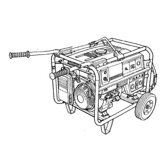
2.COMPONENT IDENTIFICATION GFCI RECEPTACLE ---I---- VOLTAGE SELECTOR OIL ALERT SWITCH LAMP HANGER AC CIRCUIT I)REAKER ENGINE SWITCH RECEPTACLES GROUND TERMINAL WHEEL AIR CLEANER ENGINE OIL FILLER CAP FUEL VALVE AUTO-THROTTLE SWITCH 1 ENGINE OIL DRAIN PLUG ENGINE SERIAL NUMBER RECOIL STARTER GRIP... - Page 9 FUEL FILLER CAP OCCUPANTS (GFCI) TEST RECORD PARK PLUG CAP GUARD PLATE FRAME SERIAL NUMBER BATTERY TRAY * Record the engine and frame serial numbers for your future reterence. Refer to these serial numbers when ordering parts, and when making technical or warranty inquiries (see page 46) Frame serial number:...
-
Page 10: Pre-Operation Check
Non-detergent and 2-stroke engine oils are not recommended. Check the generator on a level surface with the engine stopped. Use Honda 4-stroke oil, or an equivalent high detergent, premium quality motor oil certified meet exceed U.S. - Page 11 Honda dealer. Failure to do so is considered misuse, and damage caused by misuse is not covered by Honda’s Limited Warranty. Occasionally you may hear light spark knock while operating under heavy loads. This is no cause for concern.
- Page 12 ALCOHOL If you decide to use a gasoline containing alcohol (gasohol), be sure its octane rating is at least as high as that recommended by Honda. There are two types of “gasohol”: one containing ethanol, and the other containing methanol.
- Page 13 Air cleaner Check the air cleaner elements to be sure they are clean and in’good condition. Clean or replace the element if necessary (page 30). f-iieiq Never run the engine without the air cleaner. Rapid engine wear will result. AIR CLEANER ELEMENT...
- Page 14 4.STARTlNG THE ENGINE 1 .Make sure that the AC circuit breaker is in the OFF position. generator may be hard to start if a load is connected. AC ClRCiJlT BREAKER 2. Turn the fuel valve to the ON position. FUEL VALVE...
- Page 15 3. Pull the choke rod out to the CLOSED position. NOTE: Do not use the choke if the engine is warm or if the air temperature is high. CHOKE ROD 4. Make sure the auto-throttle switch is OFF, or more time will be required for warm up.
- Page 16 5. Start the engine 0 With recoil starter: Turn the engine switch to the ON position ENGINE SWITCH Pull the starter grip lightly until resistance is felt, then pull briskly. riiEiq Do not allow the starter grip to snap back against the engine.
- Page 17 0 With electric starter Turn the engine switch to the START position and hold it there for 5 seconds or until the engine starts. e Operating the starter motor for more than 5 seconds can damage the motor. If the engine fails to start, release the switch...
- Page 18 7. Push the choke rod to the OPEN position as the engine warms up. CHOKE RO 8. If you wish to use the auto-throttle system, turn the auto-throttle switch to the AUTO position after the engine has warmed up for 2 or 3 minutes. AUTO-THROTTLE SWITCH...
-
Page 19: Generator Use
5. GENERATOR USE prevent electrical shock from faulty appliances, make sure appliances are in good working order before connecting them to the generator. Connections for standby power to a building’s electrical system must be made by a qualified electrician and must comply with all applicable laws and electrical... - Page 20 Auto-throttle system With the switch in the AUTO position, engine speed is automatically reduced to an idle when all loads are turned off or disconnected. When appliances are turned on or reconnected, the engine resumes the rated speed. At OFF, the auto-throttle system does not operate.
- Page 21 Oil alert system The Oil Alert system is designed to prevent engine damage caused by an insufficient amount of oil in the crankcase. Before the oil level in the crankcase can fall below a safe limit, the Oil Alert system will automatically stop the engine (the engine switch will remain in the ON position).
- Page 22 Circuit Breaker The circuit breaker protects the individual circuit protectors and the 5Oh 120/24OV receptacle. The circuit breaker will automatically switch OFF it the circuit is overloaded or the appliance plugged into the circuit is faulty. If the circuit breaker is switched OFF automatically, check that the appliance is working...
- Page 23 Groung Fault Circuit Interrupter (GFCI) Receptacle Using the generator in rain, snow or near water can lead to death from electric shock. Keep the generator dry. This receptacle is protected by a Ground Fault Circuit interrupter (GFCI) for protection against electrical shock. To test, depress the “TEST”...
- Page 24 3. Turn the circuit breaker ON. 4. Make sure the auto-throttle switch is OFF CIRCUIT BREAKER 5. Press the TEST BUTTON -The RESET BUTTON should extend with a click. -If the REST BUTTON does not extend, TEST BUTTON contact authorized Honda generator dealer.
- Page 25 6. Press the RESET BUTTON flush with the test button. the RESET BUTTON is not flush with the TEST BUTOON, contact an authorized Honda generator dealer. RESET BUTTON 7. When the RESET BUTTON extends during operation: Unplug all appliance’s from the GFCI protected receptacle.
- Page 26 AC operation 1. Start the engine. 2. Turn the voltage selector switch to either position as required. NOTE: With the voltage selector switch in the “12OV/24OV” position, you can use the 120V and 240V receptacles simultaneously. If you are not using the 240V receptacle, but you require more power from the 12OV twistlock receptacle, then turn the switch to the “12OV”...
- Page 27 6. STOPPIN THE ENGINE NOTE: To stop the engine in an emergency, turn the engine switch to the OFF position. In normal use: 1. Turn the AC circuit breaker to the OFF position. AC CIRCUIT BREAKER 2. Move the engine switch to the OFF position. ENGINE SWITC...
- Page 28 If you always operate the engine at altitudes higher than 6,000 feet above sea level, have an authorized Honda generator dealer perform this carburetor modification. Even with suitable...
-
Page 29: Maintenance
Exhaust gas con-tains poisonous carbon monoxide. Use only genuine HONDA parts or their equivalent for maintenance repair. Replacement parts which of equivalent quality damage the generator. - Page 30 NOTE: (1): Service more frequently when used in dusty areas. (2): This service should be performed by an authorized Honda generator dealer unless the owner has the proper tools and is mechanically proficient. See the Honda Shop Manual.
- Page 31 Engine oil change Drain the oil while the engine is warm to assure rapid and complete draining. 1. Remove the drain plug and filler cap, and drain the oil. 2. Retighten the plug securely. 3. Refill with the recommended oil (see page 8 1 ,and check the level. 1 .I !J (I .2 US qt , 1 .O Imp qt) Oil capacity: DRAIN PLUG...
- Page 32 Air cleaner service A dirty air cleaner will restrict air flow to the carburetor. To prevent carburetor malfunction, service the air cleaner regularly (page 28 1. Service more frequently when operating the generator in extremely dusty areas. Using gasoline or flammable solvent clean the filter element can cause...
- Page 33 2. Wash the element in a solution of household detergent and warm water, then rinse thoroughly, or wash in nonflammable or high flash point so- lvent. Allow the element to dry thoroughly. 3. Soak the element in clean engine oil and squeeze out the excess oil. The engine will smoke during inital start-up if too much oil is left in the element.
-
Page 34: Starting The Engine
Sediment cup cleaning The sediment cup prevents dirt or water which may be in the fuel tank from entering the carburetor. If the engine has not been run for a long time, the sediment cup should be cleaned. .Turn the fuel valve to the OFF position. Remove the sediment cup. 2. - Page 35 Spark plug service Recommended spark plugs: BPR5ES (NGK) W 1 GEPR-U (ND) To ensure proper engine operation, the spark plug must be properly gapped and free of deposits. If the engine has been runnig, the muffler will be very hot. Be careful not to touch the muffler.
- Page 36 6.Check that the spark plug washer is in good condition, and thread the spark plug in by hand to prevent cross-threading. 7.After each spark plug is seated, tighten with a spark plug wrench compress the washer. NOTE: If installing a new spark plug, tighten l/2 turn after the spark plug seats to compress the washer.
- Page 37 Spark arrester maintenance If the generator has been running, the muffler will be very hot. Allow it to cool before proceeding. Thespark arrester must be serviced every hours to maintain efficiency. Clean the spark arrester as follows: 1. Loosen the screw by the exhaust port of the muffler and remove the spark arrester.
- Page 38 8.TRANSPORTINGISTORAGE When transporting the generator, turn the engine switch and the fuel valve OFF and keep the generator level to prevent fuel spillage. Fuel vapor or spilled fuel may ignite. Before storing the unit for an extended period: 1. Be sure the storage area is free of excessive humidity and dust.
- Page 39 d.Drain the carburetor by loosening the drain screw. Drain the gasoline into a suitable container. Gasoline extremely flammable explosive under certain conditions.Do not smoke or allow flames or sparks in the area DRAIN SCREW 3.Change the engine oil. 4.Remove the spark plug, and pour about a tablespoon of clean engine oil into the cylinder.
-
Page 40: Troubleshooting
Spilled fuel may ignite. Perform this test in a well ventilated area. e. If there are no sparks, replace the plug. f. If the new spark plug does not spark, take the generator to an authorized Honda dealer. ENGINE SWITCH... - Page 41 Fuel vapor or spilled fuel may ignite. DRAIN SCREW 7. If the engine still does not start, take the generator to an authorized Honda dealer. B.When the engine starts but stops immediately; 1. Check the oil alert lamp. If the oil alert lamp flashes when the starter is pulled, check the engine oil level and fill with the recommended oil.
-
Page 42: Wiring Diagram
IO. WIRING DIAGRAM... -
Page 43: Specifications
1 ‘I. SPECIFICATIONS Dimensions Power product description code EZCH Length 1,200 mm (47.2 Width mm (26.2 Height 720 mm (28.3 Dry weight 98.5 kg (217.2 Ibs) Engine Engine Type Gk390 Displacement 389 cm3 (23.7 cu-in) [Bore x Stroke] r88 x 64 mm (3.5 x 2.5 in) 1 Comoression Ratio 8.0 :... -
Page 44: Hanger Kit Installation
12. HANGER KIT INSTALLATION 1. Remove the upper frame. Install the hanger on it and install the upper frame on the body. BRACKET HANGER FRAME NOTE: Install at near center avoiding to install over the fuel filler cap. FUEL FILLER CAP... -
Page 45: Wheel Kit Installation
13. 2-WHEEL KIT INSTALLATION 1. Install the two wheels on the axle shaft. 2. Install the axle assembly on the generator using two bolts and nuts. 3. Install the two stands on the under frame. WHEELS 4.Remove the upper frame. Install the two handles with brackets on it using six bolts and install the upper frame on the body using four bolts. -
Page 46: Battery Tray Kit
14. BATTERY TRAY KIT 1. Install the battery guard on the frame. Set the battery tray on the battery guard and tighten the bolts. 2. Route the starter cable under the tank and connect it to the starter solenoid. 3. Connect the ground cable to the generator rear housing. 4. - Page 47 STARTER SoLEINo’D STARTER CABLE (positive) STARTER CABLE BATTERY BRACKET BATTERY GUARD BATTERY GUARD PLATE TRAY...
- Page 48 Your purchase of a Honda product is greatly appreciated by both your dealer and American Honda Motor Co.,lnc. We want to assist you in every way possible to assure your complete satisfaction with your purchase.
- Page 49 When you write or call, please provide the following information: • Model and serial numbers • Name of the dealer who sold the Honda power equipment to you • Name and address of the dealer who services your equipment •...
- Page 50 MEMO...
- Page 51 MEMO...
Need help?
Do you have a question about the EB6500 and is the answer not in the manual?
Questions and answers