
Related Manuals for Galaxy DX 959


Summary of Contents for Galaxy DX 959
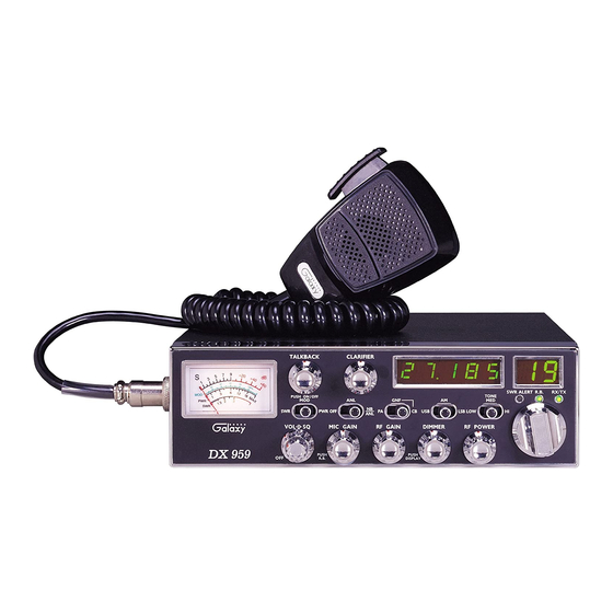
- Page 1 DX 959 SOLID STATE CITIZENS BAND AM/SSB MOBILE TRANSCEIVER OWNER’S MANUAL Printed In Malaysia AT0949011A MIC980508...
-
Page 2: Table Of Contents
TABLE OF CONTENTS SPECIFICATIONS Specifications ....... . GENERAL Channels Frequency Range 26.965 ~ 27.405 MHz Installation Emission... -
Page 3: Installation Location
INSTALLATION IGNITION NOISE INTERFERENCE Use of a mobile receiver at low signal levels is normally limited by the presence of electrical noise. The primary source of noise in automobile LOCATION installation is from the generator and ignition system in the vehicle. Under Plan the location of the transceiver and microphone bracket before starting most operating conditions, when signal level is adequate, the background the installation. -
Page 4: Tuning The Antenna For Optimum Swr
If you’re having difficulties in adjusting your antenna, check the following: TUNING THE ANTENNA FOR OPTIMUM S.W.R Since there is such a wide variety of base and mobile antennas, this section All doors must be closed when adjusting the antenna will strictly concern itself to the various types of mobile adjustable antennas. -
Page 5: Operation
4. RF GAIN CONTROL : This control is used to reduce the gain of the OPERATION receive amplifier under strong signal conditions. CONTROL FUNCTIONS FRONT PANEL 5. DIMMER CONTROL : This knob controls the level of brightness for the meter lamp, the frequency display and the channel display. Also, pushing this knob turns the meter lamp and the display LED's on and off. -
Page 6: Rear Panel
The radio does not operate when you are in the "PA" mode. The "CB" mode is normal operation of the radio. In the "GNF" mode, you are in CB operation but the Galaxy Noise Filter (GNF) is engaged. This is a special noise filter that de-emphasizes audio high frequency response in order to increase the signal-to-noise ratio of weak signals. -
Page 7: Procedure To Receive And Transmit
FREQUENCY RANGE PROCEDURE TO RECEIVE AND TRANSMIT Channel Channel Frequency Channel Channel Frequency A. MICROPHONE The receiver and transmitter are controlled by the push-to-talk switch on 26.965 MHz 27.215 MHz the microphone. Press the switch and the transmitter is activated, release switch to receive. -
Page 8: Receiving Ssb Signals
Thus when a voice is used in place of a whistle or tone, in the proper RECEIVING SSB SIGNALS listening mode the voice will be received correctly whereas in the incorrect mode, the voice will be translated backwards and cannot be made intelligible There are three types of signals presently used for communications in the by the CLARIFIER control. -
Page 9: Alternate Microphones And Installation
Before beginning the actual wiring, read carefully the circuit and wiring ALTERNATE MICROPHONES AND INSTALLATION information provided with the microphone you select. Use the minimum heat required in soldering the connections. Keep the exposed wire lengths to a For best results, the user should select a low-impedance dynamic type minimum to avoid shorting when the microphone plug is reassembled. -
Page 10: Maintenance And Adjustment
If a vise or clamping tool is not available, the pin receptacle body can be 8. Upon completion of the microphone plug wiring, connect and secure the held in a stationary position by inserting it into the microphone jack on microphone plug in the transceiver. -
Page 11: A Few Rules That Should Be Obeyed
A FEW RULES THAT SHOULD BE OBEYED USE CH 9 FOR EMERGENCY MESSAGES ONLY 1. You are not allowed to carry on a conversation with another station for The FCC gives the following examples of permitted and prohibited types of more than five minutes at a time without taking a one-minute break, to communications for use in an emergency. -
Page 12: Warranty
• We will repair and return your radio as soon as we can. We appreciate your choosing a Galaxy radio and we want you to be on the air as much as possible! Be sure to visit our web site at www.GalaxyRadios.com...
Need help?
Do you have a question about the DX 959 and is the answer not in the manual?
Questions and answers