Advertisement
Advertisement
Table of Contents

Related Manuals for Sonic Frontiers Sonic Frontiers Power 1


Summary of Contents for Sonic Frontiers Sonic Frontiers Power 1
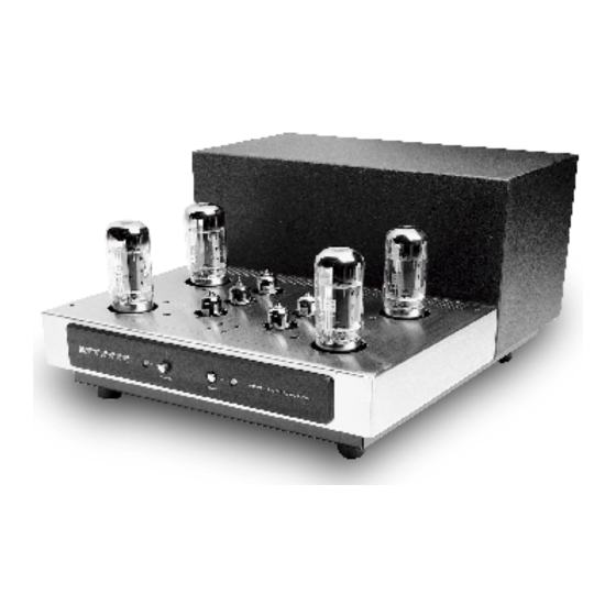
- Page 1 Operating Manual for the Sonic Frontiers Power 1 Stereo Amplifier...
-
Page 2: Table Of Contents
Operating Manual for the Sonic Frontiers Power 1 Stereo Amplifier We at Sonic Frontiers hope you will derive many years of listening pleasure from your new Power 1 Amplifier. This Operating Manual contains important information regard- ing the operation and care of this Amplifier. Be sure to read this manual carefully and follow these instructions in order to keep it performing and sounding its best. -
Page 3: Unpacking
Unpacking At this point we can assume that you have successfully opened the box flaps and found this manual. The box was designed to ensure the safe transport of the amplifier. Sonic Frontiers strongly recommends the storage of the Power 1 box in a safe, dry place. In the event that the amplifier may have to be shipped in the future, the original box is the best means for the protection and safety of the Power 1 during transportation. -
Page 4: Quick Setup
Quick Setup At this point, we urge you to read and understand this manual in its entirety. But if you desire immediate action and have skill and/or past experience with tube hardware, fol- low these steps. 1. Place the amp on a hard flat surface that will not impede airflow under the amplifier’s chassis (carpeting or area rugs are NOT acceptable as hard surfaces). -
Page 5: Reference Diagrams
Reference Diagrams This drawing is referred to as the “Tube Top” within the instructional text. Tube locations V1 to V3 and V6 to V8 indicate placement for the six 6922 tubes. Locations V4, V5, V9, V10 indicate placement for the 6550C/KT88 power tubes. Holes on the Tube Top labeled “A”... - Page 6 This drawing is referred to as the “Front Panel” within the instructional text. This drawing is referred to as the “Rear Panel” within the instructional text. Power Switch Standby Switch Power LED (Green - Power; Red - Both Channels in Mute; Orange (Red + Green) - One Channel in Mute) Standby LED (Green - Operate;...
-
Page 7: Installing The Tubes
Installing the Tubes Be sure the amplifier is OFF (Power Switch Out) before installing any tubes or when any of the tube sockets are empty. Wearing the cotton gloves provided with the amplifier when handling tubes will prevent skin oils from depositing on the glass surface of the tubes. The oils could cause the tubes to become “gassy”... - Page 8 Installing the Tubes (cont’d) When installing the 6550C/KT88 power tubes, match the numbers designated on the metal base of the tube or the tube boxes to the corresponding markings printed on the tube top (V4, V5 and V9, V10) and be sure the center pin key locator is in alignment with the slot in the center of the socket.
-
Page 9: Controls, Functions And Connections
Controls, Functions and Connections Front Panel Refer to Reference Diagrams (Page 4). Power Switch This push button provides control over the AC power from your wall outlet. When OFF (out position) nothing on the amplifier is functional. When ON (depressed) the amplifier will operate normally. - Page 10 H Fuse Location (cont’d) Damage due to bypassing the fuse or due to replacement of a fuse with one of a higher rating will not be covered under the warranty. To access the fuse, insert the slotted screw- driver, pushing to compress the internal spring and turn counterclockwise 1/4 turn to unlock the housing.
-
Page 11: Biasing Of The Power Tubes
Biasing of the Power Tubes Bias voltage applied to the grids of the power tubes in the output stage should be checked from time to time (once a month) to keep these tubes operating at the optimum operating point. A properly biased power tube will have a longer, happier life. To check the bias of the 6550C/KT88 tubes, place the amplifier in MUTE via the Input Selector Switches (I), with the power on and the amplifier in OPERATE mode (STANDBY LED Green;... -
Page 12: Adjustment For Load Impedance
Adjustment for Speaker Load Impedance Note: Adjustment for load impedance should only be done by an authorized Sonic Frontiers dealer, distributor or service technician. Any damage to the amplifier as a result of a person(s) not authorized by Sonic Frontiers will not be covered under warranty. Warning: Dangerous voltages exist within this amplifier. - Page 13 Adjustment for Speaker Load Impedance Cont’d The final connections should resemble these diagrams: 8 Ohm Impedance Connections REAR OF THE AMPLIFIER (Left Channel Shown) 4 Ohm Impedance Connections REAR OF THE AMPLIFIER (Left Channel Shown) 5. Repeat for each channel. 6.
-
Page 14: Care And Maintenance
Care and Maintenance Placement The amplifier must be placed on a hard flat surface with plenty of unobstructed space around the Power 1 to allow for free movement of air for proper cooling. If the amplifier is to be placed on a carpeted floor, a Wood, Ceramic, Concrete, Marble... tile or slab 15”... -
Page 15: Troubleshooting
Troubleshooting If at any time the amplifier should fail to work, follow these steps: 1. Check that all tubes are fully seated in correct sockets and all tube filaments are lit. 2. Check all connections at the rear panel. 3. Check that the amplifier is not in MUTE mode. 4. -
Page 16: Warranty
Warranty Disclaimer of Liability Under no circumstances does Sonic Frontiers, Inc. assume liability or responsibility for injury or damages sustained in the use or operation of this equipment or for damages to any other equipment connected to it. Sonic Frontiers, Inc. reserves the right to make design changes or improvements without the obligation to revise prior versions. -
Page 17: Specifications
Specifications Note: Power ratings based on a nominal power line input (appropriate for the country in which it is used). All specifications are made on the 8 ohm taps, utilizing an 8 ohm load unless otherwise specified. Power Output: 55 watts continuous at 8 ohms from 20 Hz to 20 kHz with less than 1% total harm o n i c d i s t o rtion terminated with rated load (typically <0.2% @ 55 watts 1 kHz), both channels driven.
Need help?
Do you have a question about the Sonic Frontiers Power 1 and is the answer not in the manual?
Questions and answers