
Related Manuals for Clarke Power FG3050


Summary of Contents for Clarke Power FG3050
- Page 1 GENERATOR MODEL NO: FG3050 PART NO: 8857705 OPERATION & MAINTENANCE INSTRUCTIONS LS0310...
-
Page 2: Introduction
INTRODUCTION Thank you for purchasing this CLARKE Generator. Before attempting to use this product, please read this manual thoroughly and follow the instructions carefully. In doing so you will ensure the safety of yourself and that of others around you, and you can look forward to your purchase giving you long and satisfactory service. -
Page 3: Table Of Contents
TABLE OF CONTENTS INTRODUCTION ............... 2 GUARANTEE ..............2 TABLE OF CONTENTS ............3 GENERAL SAFETY RULES ..........4 Work area ................4 Positioning the Generator ...........4 Fire Prevention ..............4 Prevention of electric shock ..........5 Additional safety rules for Generators .......5 SAFETY SYMBOLS ............ -
Page 4: General Safety Rules
GENERAL SAFETY RULES WARNING: EXHAUST FUMES CAN BE EXTREMELY DANGEROUS IF INHALED WORK AREA • Always use in a well ventilated area. • Always position the exhaust outlet away from people. • Never use indoors or in a confined space. •... -
Page 5: Prevention Of Electric Shock
6. Never start the engine if there is spilled fuel. Any spillage must be wiped clean and the generator allowed to dry before attempting to start the engine. PREVENTION OF ELECTRIC SHOCK 1. Never use the generator in wet conditions unless it is well protected/ covered. -
Page 6: Safety Symbols
SAFETY SYMBOLS Caution - The user should be aware of a general hazard Dangerous Voltage Flammable Hot Surface - Do not touch Poisonous fumes - Do not use the generator in an enclosed space. Read Instruction manual before use. -
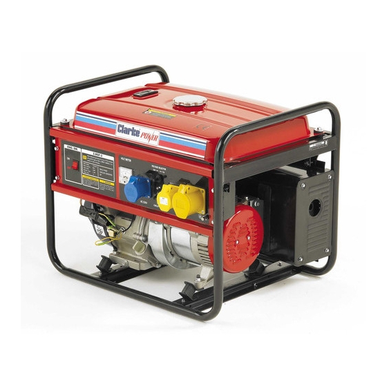
Page 7: Generator Overview
GENERATOR OVERVIEW DESCRIPTION NO DESCRIPTION Fuel level gauge Starting handle Fuel tank cap Fuel supply valve AC plug sockets (2x115V, 1 x 230V) Air filter AC circuit breaker Choke Lever Voltmeter Earth terminal Dipstick Muffler Engine switch Spark plug Drain plug... -
Page 8: Unpacking And Assembly
UNPACKING AND ASSEMBLY Unpack your Generator and check to ensure the following items are present. Should there be any deficiency or damage caused during transit contact your Clarke dealer immediately. • The Generator • Spark Plug Box Spanner • Tommy Bar BEFORE USING THE GENERATOR IMPORTANT: Generators should ALWAYS be earthed. -
Page 9: Checking The Engine Oil Level
CHECKING THE ENGINE OIL LEVEL WARNING: TO CARRY OUT THIS CHECK, PLACE THE GENERATOR ON LEVEL GROUND WITH THE ENGINE SWITCHED OFF (O). WARNING: TAKE CARE NOT TO TOUCH ANY HOT PARTS OF THE GENERATOR WHEN CHECKING THE OIL LEVEL. 1. -
Page 10: Checking The Fuel Level
CHECKING THE FUEL LEVEL 1. Check the fuel level on the fuel gauge. The fuel gauge will show as red when you have fuel in the tank turning white as the fuel level decreases Empty Full To add fuel, open the fuel filler Fuel filler cap cap. -
Page 11: Using Your Generator
USING YOUR GENERATOR STARTING THE ENGINE 1. Remove all connections from the AC sockets. 2. Set the AC breaker to the off position. 3. Turn on the fuel supply valve. 4. If you are starting the generator ‘cold’ set the choke lever to the ON position. - Page 12 5. Set the engine switch to ‘I’ 6. Pull the starting handle lightly until you start to feel resistance and then pull up sharply to start the generator. NOTE: You may have to do this more than once. WARNING: ONCE THE GENERATOR HAS STARTED, RELEASE THE STARTING HANDLE SLOWLY TO AVOID INJURY/DAMAGE AS IT WHIPS BACK.
-
Page 13: Connecting Electrical Devices
CONNECTING ELECTRICAL DEVICES The generator can supply both 230V AC and 115V AC. 1. Connect the appliance to the generator starting with the device that draws the most current. 2. Select the voltage that you require using the voltage selector switch. -
Page 14: Shutting Down The Generator
SHUTTING DOWN THE GENERATOR 1. Disconnect all appliances connected to the generator. 2. Set the circuit breaker to ‘OFF’. 3. Set the engine switch to ‘O’. 4. Set the fuel supply valve to OFF. NOTE: To stop the generator in an emergency simply set the engine switch to ‘O’... -
Page 15: Maintenance
MAINTENANCE CHANGING THE ENGINE OIL CAUTION: PROLONGED EXPOSURE TO USED ENGINE OIL IS DANGEROUS, ALWAYS WASH YOUR HANDS THOROUGHLY AFTER HANDLING USED ENGINE OIL. 1. Unscrew and remove the oil filler cap/dipstick. 2. Place a oil collection tray under the drain plug. 3. -
Page 16: Changing The Spark Plugs
CHANGING THE SPARK PLUGS CAUTION: ALLOW THE ENGINE TO COOL BEFORE REMOVING THE SPARK PLUG. 1. Remove the spark plug cap from the spark plug. Use the supplied spark plug spanner to remove the spark plug. 3. Remove any carbon that has accumulated around the sparkplug. -
Page 17: Checking The Air Filter
2. Remove the air filter element. 3. Make sure that the air filter is clean and not damaged. • If the air filter is damaged contact Clarke spare parts department for a replacement See page 25. • If the filter is dirty, wash the filter... -
Page 18: Cleaning The Fuel Valve Filter / Draining The Fuel Tank
CLEANING THE FUEL VALVE FILTER / DRAINING THE FUEL TANK 1. Set the fuel supply valve to OFF. 2. U nscrew and remove the cup, then remove the valve filter and ‘O’ ring. 3. Wash these parts in a non- inflammable solvent. -
Page 19: Troubleshooting
The air filter is dirty Clean the air filter, See page 17 difficult to start The fuel filter is dirty Clean the fuel filter, See page 18 If this does not solve your problem, please contact the clarke service department. See page 25... -
Page 20: Specifications
SPECIFICATIONS FG3050 Engine Engine Model 173F Type Petrol air cooled 4-Stroke OHV single cylinder Displacement (cm Max. power output (hp/rpm) 8/3600 Ignition type Start system Recoil Fuel tank capacity (L) Fuel consumption (L/hr.) Duration of run (h) Engine oil capacity (L) Guaranteed sound power (L Generator Rated Frequency (Hz) -
Page 21: Exploded Diagram & Parts List
EXPLODED DIAGRAM & PARTS LIST... - Page 22 EXPLODED DIAGRAM & PARTS LIST DESCRIPTION PART NO DESCRIPTION PART NO Crankcase RKFG3050001 Lead wind RKFG3050029 cover Oil seal, RKFG3050002 crankshaft Gasket, RKFG3050030 cylinder head Washer RKFG3050003 cover Drain plug RKFG3050004 Cylinder head RKFG3050031 cover Assy Oil seal, RKFG3050005 regulating sway Bolt RKFG3050032 Cylinder head...
- Page 23 EXPLODED DIAGRAM & PARTS LIST DESCRIPTION PART NO DESCRIPTION PART NO Gasket, air RKFG3050057 Gasket, exhaust RKFG3050087 cleaner pipe Manual choke RKFG3050058 Outer hood RKFG3050088 Assy Muffler RKFG3050089 Gasket, air RKFG3050059 Inner hood RKFG3050090 cleaner Side hood RKFG3050091 Carburetor Assy 1 RKFG3050060 Gasket, inner RKFG3050092...
- Page 24 EXPLODED DIAGRAM & PARTS LIST DESCRIPTION PART NO DESCRIPTION PART NO Bolt M5×213 RKFG3050117 Earth terminal RKFG3050146 Bearing 6204- RKFG3050118 Voltmeter RKFG3050147 Rotor Assy RKFG3050119 DC terminal RKFG3050148 Plain washer RKFG3050120 Ignition switch RKFG3050149 Bolt M10×265 RKFG3050121 Control panel RKFG3050150 Generator stay RKFG3050122 Bearing 6202...
-
Page 25: Parts And Servicing
PARTS AND SERVICING For Parts & Servicing, please contact your nearest dealer, or CLARKE International, on one of the following numbers. PARTS & SERVICE TEL: 020 8988 7400 PARTS & SERVICE FAX: 020 8558 3622 or e-mail as follows: PARTS: Parts@clarkeinternational.com... -
Page 26: Declaration Of Conformity
DECLARATION OF CONFORMITY... - Page 27 DECLARATION OF CONFORMITY...
Need help?
Do you have a question about the Power FG3050 and is the answer not in the manual?
Questions and answers