
Related Manuals for ASROCK ConRoe945G-DVI


Summary of Contents for ASROCK ConRoe945G-DVI
-
Page 1: User Manual
ConRoe945G-DVI User Manual Version 1.1 Published November 2006 Copyright©2006 ASRock INC. All rights reserved. 1 1 1 1 1... - Page 2 (including damages for loss of profits, loss of business, loss of data, interruption of business and the like), even if ASRock has been advised of the possibility of such damages arising from any defect or error in the manual or product.
-
Page 3: Table Of Contents
Contents Contents Contents Contents Contents 1 Introduction 1 Introduction 1 Introduction 1 Introduction 1 Introduction ....................................................5 5 5 5 5 1.1 Package Contents ............5 1.2 Specifications ..............6 1.3 Minimum Hardware Requirement Table for Windows ®... - Page 4 3.4 Hardware Health Event Monitoring Screen ....38 3.5 Boot Screen ..............39 3.5.1 Boot Settings Configuration ........39 3.6 Security Screen ............40 3.7 Exit Screen ..............41 4 Software Support 4 Software Support 4 Software Support ........... 4 Software Support 4 Software Support ...........
-
Page 5: Introduction
In case any modifications of this manual occur, the updated version will be available on ASRock website without further notice. You may find the latest VGA cards and CPU support lists on ASRock website as well. ASRock website http://www.asrock.com 1.1 Package Contents... -
Page 6: Specifications
- Support DDRII667/533 (see CAUTION 4) - Max. capacity: 4GB Hybrid Booster - CPU Frequency Stepless Control (see CAUTION 5) - ASRock U-COP (see CAUTION 6) - Boot Failure Guard (B.F.G.) Expansion Slot - 2 x PCI slots - 1 x PCI Express x16 slot... - Page 7 - 4 x Ready-to-Use USB 2.0 Ports - 1 x RJ-45 LAN Port - HD Audio Jack: Side Speaker/Rear Speaker/Central/Bass/ Line in/Front Speaker/Microphone (see CAUTION 7) Connector - 4 x SATAII 3.0 Gb/s connectors (No Support for RAID and “Hot Plug” functions) (see CAUTION 8) - 1 x ATA100 IDE connector (supports 2 x IDE devices) - 1 x Floppy connector - 1 x IR header...
- Page 8 10. Microsoft Windows Vista driver is not ready yet. We will update it to our ® ® website in the future. Please visit our website for Microsoft Windows Vista driver and related information. ASRock website http://www.asrock.com 8 8 8 8 8...
-
Page 9: Vista Tm Premium And Basic Logo
Premium or Basic logo, the shared memory size of onboard VGA can be adjusted up to 128MB. * If you plan to use external graphics card on this motherboard, please refer to Premium Discrete requirement at http://www.asrock.com 9 9 9 9 9... -
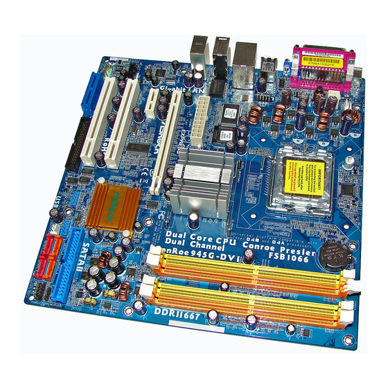
Page 10: Motherboard Layout
1.4 Motherboard Layout 1.4 Motherboard Layout 1.4 Motherboard Layout 1.4 Motherboard Layout 1.4 Motherboard Layout 24.4cm (9.6 in) CLRCMOS1 PS2_USB_PWR1 Mouse CMOS CPU_FAN1 Battery USB 2.0 T: USB2 B: USB3 USB 2.0 Top: T: USB0 RJ-45 B: USB1 Super Intel BIOS 945G Chipset... -
Page 11: Hd 8Ch I/O
HD 8CH I/O HD 8CH I/O HD 8CH I/O HD 8CH I/O HD 8CH I/O Parallel Port Microphone (Pink) RJ-45 Port USB 2.0 Ports (USB01) Side Speaker (Gray) USB 2.0 Ports (USB23) Rear Speaker (Black) VGA Port Central / Bass (Orange) PS/2 Keyboard Port (Purple) Line In (Light Blue) PS/2 Mouse Port (Green) -
Page 12: Installation
Chapter 2 Installation Chapter 2 Installation Chapter 2 Installation Chapter 2 Installation Chapter 2 Installation ConRoe945G-DVI is a Micro ATX form factor (9.6" x 9.6", 24.4 x 24.4 cm) motherboard. Before you install the motherboard, study the configuration of your chassis to ensure that the motherboard fits into it. -
Page 13: Cpu Installation
2.3 CPU Installation 2.3 CPU Installation 2.3 CPU Installation 2.3 CPU Installation 2.3 CPU Installation For the installation of Intel 775-LAND CPU, please follow the steps below. 775-Pin Socket Overview Before you insert the 775-LAND CPU into the socket, please check if the CPU surface is unclean or if there is any bent pin on the socket. - Page 14 For proper inserting, please ensure to match the two orientation key notches of the CPU with the two alignment keys of the socket. Step 2-3. Carefully place the CPU into the socket by using a purely vertical motion. Step 2-4. Verify that the CPU is within the socket and properly mated to the orient keys.
-
Page 15: Installation Of Heatsink And Cpu Fan
Installation of CPU Fan and Heatsink Installation of CPU Fan and Heatsink Installation of CPU Fan and Heatsink Installation of CPU Fan and Heatsink Installation of CPU Fan and Heatsink This motherboard is equipped with 775-Pin socket that supports Intel 775-LAND CPU. Please adopt the type of heatsink and cooling fan compliant with Intel 775-LAND CPU to dissipate heat. -
Page 16: Installation Of Memory Modules (Dimm)
2.5 Installation of Memory Modules (DIMM) 2.5 Installation of Memory Modules (DIMM) 2.5 Installation of Memory Modules (DIMM) 2.5 Installation of Memory Modules (DIMM) 2.5 Installation of Memory Modules (DIMM) ConRoe945G-DVI motherboard provides four 240-pin DDRII (Double Data Rate II) DIMM slots, and supports Dual Channel Memory Technology. For dual channel configuration, you always need to install identical (the same brand, speed, size and chip-type) DDRII DIMM pair in the slots of the same color. - Page 17 Installing a DIMM Installing a DIMM Installing a DIMM Installing a DIMM Installing a DIMM Please make sure to disconnect power supply before adding or removing DIMMs or the system components. Step 1. Unlock a DIMM slot by pressing the retaining clips outward. Step 2.
-
Page 18: Expansion Slots (Pci, Hdmr And Pci Express Slots)
The HDMR slot is shared with PCI2 slot. PCIE Slots: PCIE1 (PCIE x16 slot) is used for PCI Express cards with x16 lane width graphics cards or ASRock DVI Graphics-SI card. PCIE2 (PCIE x1 slot) is used for PCI Express cards with x1 lane width cards, such as Gigabit LAN card, SATA2 card, etc. - Page 19 Step 1. Install the DVI Graphics-SI card to PCIE1 (PCIE x16 slot). Please refer to the expansion card installation procedures on page 18 for details. DVI Graphics-SI card Step 2. Connect the DVI-D connector of DVI-D input monitor to the DVI-D output connector of DVI Graphics-SI card which is inserted to PCIE1 (PCIE x16 slot) on this motherboard.
-
Page 20: Jumpers Setup
2.8 Jumpers Setup 2.8 Jumpers Setup 2.8 Jumpers Setup 2.8 Jumpers Setup 2.8 Jumpers Setup The illustration shows how jumpers are setup. When the jumper cap is placed on pins, the jumper is “Short”. If no jumper cap is placed on pins, the jumper is “Open”. The illustration shows a 3-pin jumper whose pin1 and pin2 are “Short”... -
Page 21: Onboard Headers And Connectors
2.9 Onboard Headers and Connectors 2.9 Onboard Headers and Connectors 2.9 Onboard Headers and Connectors 2.9 Onboard Headers and Connectors 2.9 Onboard Headers and Connectors Onboard headers and connectors are NOT jumpers. Do NOT place jumper caps over these headers and connectors. Placing jumper caps over the headers and connectors will cause permanent damage of the motherboard! FDD connector... - Page 22 USB 2.0 Headers Besides four default USB 2.0 USB_PWR ports on the I/O panel, there are (9-pin USB6_7) DUMMY two USB 2.0 headers on this (see p.10 No. 18) motherboard. Each USB 2.0 header can support two USB USB_PWR 2.0 ports. (9-pin USB4_5) USB_PWR (see p.10 No.
- Page 23 F. Enter Windows system. Click the icon on the lower right hand taskbar to enter Realtek HD Audio Manager. Click “Audio I/O”, select “Connector Settings” , choose “Disable front panel jack detection”, and save the change by clicking “OK”. System Panel Header PLED+ This header accommodates PLED-...
-
Page 24: Sataii Hard Disk Setup Guide
2.10 2.10 SA 2.10 SAT T T T T AII Hard Disk Setup Guide AII Hard Disk Setup Guide AII Hard Disk Setup Guide AII Hard Disk Setup Guide 2.10 2.10 AII Hard Disk Setup Guide Before installing SATAII hard disk to your computer, please carefully read below SATAII hard disk setup guide. -
Page 25: Installation
2.11 2.11 2.11 Serial A Serial A Serial AT T T T T A (SA Serial A A (SA A (SAT T T T T A) / Serial A A (SA A) / Serial A A) / Serial A A) / Serial AT T T T T AII (SA AII (SA AII (SA AII (SAT T T T T AII) Hard Disks... -
Page 26: Bios Setup Utility
Chapter 3 BIOS SETUP UTILITY Chapter 3 BIOS SETUP UTILITY Chapter 3 BIOS SETUP UTILITY Chapter 3 BIOS SETUP UTILITY Chapter 3 BIOS SETUP UTILITY Introduction Introduction Introduction Introduction Introduction This section explains how to use the BIOS SETUP UTILITY to configure your system. The BIOS FWH chip on the motherboard stores the BIOS SETUP UTILITY. -
Page 27: Navigation Keys
3.1.2 3.1.2 Navigation Keys 3.1.2 Navigation Keys Navigation Keys Navigation Keys 3.1.2 3.1.2 Navigation Keys Please check the following table for the function description of each navigation key. Navigation Key(s) Function Description Moves cursor left or right to select Screens Moves cursor up or down to select items + / - To change option for the selected items... -
Page 28: Cpu Configuration
BIOS SETUP UTILITY Main Advanced H/W Monitor Boot Security Exit Configure CPU Advanced Settings WARNING : Setting wrong values in below sections may cause system to malfunction. CPU Configuration Chipset Configuration ACPI Configuration IDE Configuration PCIPnP Configuration Select Screen Floppy Configuration Select Item SuperIO Configuration Enter Go to Sub Screen... - Page 29 an item Ratio CMOS Setting appears to allow you changing the ratio value of this motherboard. Ratio Actual Value This is a read-only item, which displays the ratio actual value of this motherboard. Ratio CMOS Setting If the ratio status is unlocked, you will find this item appear to allow you changing the ratio value of this motherboard.
-
Page 30: Chipset Configuration
as “Portable/Laptop” to enable this function. This option will be hidden if the current CPU does not support Intel SpeedStep(tm) tech.. 3.3.2 3.3.2 3.3.2 Chipset Configuration 3.3.2 3.3.2 Chipset Configuration Chipset Configuration Chipset Configuration Chipset Configuration BIOS SETUP UTILITY Advanced Chipset Configuration Options Auto... - Page 31 [4 DRAM Clocks], [5 DRAM Clocks], [6 DRAM Clocks], [7 DRAM Clocks], [8 DRAM Clocks], [9 DRAM Clocks], [10 DRAM Clocks], [11 DRAM Clocks], [12 DRAM Clocks], [13 DRAM Clocks], [14 DRAM Clocks], and [15 DRAM Clocks]. Initate Graphic Adapter This item shows the primary graphic adapter.
-
Page 32: Acpi Configuration
3.3.3 3.3.3 3.3.3 ACPI Configuration ACPI Configuration ACPI Configuration ACPI Configuration 3.3.3 3.3.3 ACPI Configuration BIOS SETUP UTILITY Advanced ACPI Configuration Select auto-detect or disable the STR feature. [Disabled] Suspend To RAM [Power Off] Restore on AC/Power Loss [Disabled] Ring-In Power On [Disabled] PCI Devices Power On [Disabled]... -
Page 33: Ide Configuration
3.3.4 3.3.4 IDE Configuration IDE Configuration 3.3.4 3.3.4 IDE Configuration 3.3.4 IDE Configuration IDE Configuration BIOS SETUP UTILITY Advanced Set [Compatible] IDE Configuration when Legacy OS (MS-DOS, Win NT) [Enhanced] ATA/IDE Configuration device is used. Set [Enhanced] SATAII 1 [Hard Disk] when Native OS SATAII 2 [Not Detected]... - Page 34 BIOS SETUP UTILITY Advanced Primary IDE Master Select the type of device connected :Hard Disk Device to the system. Vendor :ST340014A Size :40.0 GB LBA Mode :Supported Block Mode :16Sectors PIO Mode Async DMA :MultiWord DMA-2 Ultra DMA :Ultra DMA-5 S.M.A.R.T.
-
Page 35: Pcipnp Configuration
S.M.A.R.T. Use this item to enable or disable the S.M.A.R.T. (Self-Monitoring, Analysis, and Reporting Technology) feature. Configuration options: [Disabled], [Auto], [Enabled]. 32-Bit Data Transfer Use this item to enable 32-bit access to maximize the IDE hard disk data transfer rate. 3.3.5 3.3.5 3.3.5... -
Page 36: Floppy Configuration
3.3.6 3.3.6 Floppy Configuration Floppy Configuration 3.3.6 3.3.6 Floppy Configuration 3.3.6 Floppy Configuration Floppy Configuration In this section, you may configure the type of your floppy drive. BIOS SETUP UTILITY Advanced Floppy Configuration Select the type of floppy drive connected to the [1.44 MB 3 "] Floppy A system. -
Page 37: Usb Configuration
Parallel Port Address Use this item to set the address for the onboard parallel port or disable it. Configuration options: [Disabled], [378], and [278]. Parallel Port Mode Use this item to set the operation mode of the parallel port. The default value is [ECP+EPP]. -
Page 38: Hardware Health Event Monitoring Screen
3.4 Hardware Health Event Monitoring Screen Hardware Health Event Monitoring Screen Hardware Health Event Monitoring Screen Hardware Health Event Monitoring Screen Hardware Health Event Monitoring Screen In this section, it allows you to monitor the status of the hardware on your system, including the parameters of the CPU temperature, motherboard temperature, CPU fan speed, chassis fan speed, and the critical voltage. -
Page 39: Boot Screen
3.5 Boot Screen Boot Screen Boot Screen Boot Screen Boot Screen In this section, it will display the available devices on your system for you to config- ure the boot settings and the boot priority. BIOS SETUP UTILITY Main Advanced H/W Monitor Boot Security... -
Page 40: Security Screen
3.6 Security Screen Security Screen Security Screen Security Screen Security Screen In this section, you may set or change the supervisor/user password for the system. For the user password, you may also clear it. BIOS SETUP UTILITY Main Advanced H/W Monitor Boot Security Exit... -
Page 41: Exit Screen
3.7 Exit Screen Exit Screen Exit Screen Exit Screen Exit Screen BIOS SETUP UTILITY Main Advanced H/W Monitro Boot Security Exit Exit Options Exit system setup after saving the changes. Save Changes and Exit Discard Changes and Exit F10 key can be used Discard Changes for this operation. -
Page 42: Install Operating System
C o n t a c t I n f o r m a t i o n If you need to contact ASRock or want to know more about ASRock, welcome to visit ASRock’s website at http://www.asrock.com; or you may contact your...
Need help?
Do you have a question about the ConRoe945G-DVI and is the answer not in the manual?
Questions and answers