
Related Manuals for AOpen MX46-533 Max


Summary of Contents for AOpen MX46-533 Max
-
Page 1: Mx46-533V / Mx46-533 Max
MX46-533V / MX46-533 Max DOC. NO.: MX46533V-OL-E0208A... -
Page 2: Table Of Contents
’ ’ MX46-533V / MX46-533 Max...........................1 What’s in this manual ..................................2 You Must Notice .................................... 9 Before You Start ..................................10 Overview ......................................11 Feature Highlight ..................................12 Quick Installation Procedure ............................... 16 Motherboard Map ..................................17 Block Diagram ..................................... 18 Hardware Installation ..........................19 About “User Upgrade Optional”... - Page 3 Front Panel Connector ................................32 ATX Power Connector................................. 33 AC Power Auto Recovery................................33 IDE and Floppy Connector ................................34 ATA133 Supported ..................................36 IrDA Connector.................................... 37 AGP (Accelerated Graphic Port) Expansion Slot ........................38 WOL (Wake on LAN)................................... 39 Support 10/100 Mbps LAN onboard............................
- Page 4 Battery-less and Long Life Design .............................. 52 Over-current Protection ................................53 Hardware Monitoring ................................... 54 Resettable Fuse ..................................55 Low ESR Capacitor ..................................56 Layout (Frequency Isolation Wall)............................... 58 Enlarged Aluminum Heatsink ..............................59 Driver and Utility ............................60 Auto-run Menu from Bonus CD ..............................61 Install IDE Driver ..................................
- Page 5 AC97 ......................................88 ACPI (Advanced Configuration & Power Interface) ........................88 AGP (Accelerated Graphic Port) ..............................88 AMR (Audio/Modem Riser) ................................. 89 AOpen Bonus Pack CD................................89 APM (Advanced Power Management) ............................89 ATA (AT Attachment) ................................... 89 ATA/66 ......................................89 ATA/100 .......................................
- Page 6 CNR (Communication and Networking Riser)..........................90 CODEC (Coding and Decoding) ..............................91 DDR (Double Data Rated) SDRAM............................. 91 DIMM (Dual In Line Memory Module) ............................91 DMA (Direct Memory Access) ..............................91 ECC (Error Checking and Correction)............................92 EDO (Extended Data Output) Memory............................92 EEPROM (Electronic Erasable Programmable ROM) ........................
- Page 7 PC-133 DIMM....................................95 PC-1600 or PC-2100 DDR DRAM .............................. 95 PCI (Peripheral Component Interface) Bus..........................95 PDF Format....................................96 PnP (Plug and Play) ..................................96 POST (Power-On Self Test) ................................ 96 RDRAM (Rambus DRAM)................................96 RIMM (Rambus Inline Memory Module)............................97 SDRAM (Synchronous DRAM) ..............................
-
Page 8: 3 V / Mx
Product Registration..........................107 How to Contact Us..........................108... -
Page 9: You Must Notice
All of the specifications and information contained in this manual are subject to change without notice. AOpen reserves the right to revise this publication and to make reasonable changes. AOpen assumes no responsibility for any errors or inaccuracies that may appear in this manual, including the products and software described in it. -
Page 10: Before You Start
This Online Manual will introduce to the user how this product is installed. All useful information will be described in later chapters. Please This Online Manual will introduce to the user how this product is installed. All useful information will be described in later chapters. Please keep this manual carefully for future upgrades or system configuration changes. -
Page 11: Overview
® Thank you for choosing AOpen MX46-533V / MX46-533 Max motherboard. MX46-533V / MX46-533 Max is Intel Socket 478 motherboard (M/B) based on the micro-ATX form factor featuring the SIS 651 chipset. As high performance chipset built in the M/B, MX46-533V / ®... -
Page 12: Feature Highlight
® ® Supports Intel Socket 478 Pentium 4 (Willamette / Northwood) 1.4GHz~2.4GHz+ with 533MHz Front Side Bus (FSB) designed for Socket 478 technology. Chipset MX46-533V This motherboard is equipped with SIS 651 chipset. SIS 651 chipset consists of host interface Controller and integrated high performance DDR SDRAM Host system controller, which provides superior performance among CPU, SDRAM, and AGP buses. -
Page 13: Expansion Slots
Random Access Memory). Watch Dog Timer Includes AOpen “Watch Dog Timer” function that can auto-reset system in 4.8 seconds when you fail to system overclocking. 1MHz Stepping Frequency Adjustment Provides “1MHz Stepping Frequency Adjustment” function in the BIOS. This magic function allows you to adjust CPU frequency from 100~248MHz by 1MHz stepping adjustment, and helps your system get maximum performance. - Page 14 LAN Port On the strength of ntergrated SIS LAN Controller with Realtek Ethernet PHY on board, which is a highly integrated Platform LAN Connect device, it provides 10/100 Mbps Ethernet for office and home use. Ultra DMA 33/66/100/133 Bus Mater IDE Comes with an on-board PCI Bus Master IDE controller with two connectors that support four IDE devices in two channels, supports Ultra 33/66/100/133, PIO Modes 3 and 4 and Bus Master IDE DMA Mode 6, and supports Enhanced IDE devices.
- Page 15 On-board IEEE 1394 Connectors (MX46-533 Max Only) Comes with two onboard IEEE 1394 connectors that provide ports for IEEE 1394 devices, such as digital camera or others IEEE 1394 storage devices. Power Management/Plug and Play Supports the power management function that confirms to the power-saving standards of the U.S. Environmental Protection Agency (EPA) Energy Star program.
-
Page 16: Quick Installation Procedure
This page gives you a quick procedure on how to install your system. Follow each step accordingly. Installing CPU and Fan Installing System Memory (DIMM) Connecting Front Panel Cable Connecting IDE and Floppy Cable Connecting ATX Power Cable Connecting Back Panel Cable Power-on and Load BIOS Setup Default Setting CPU Frequency Reboot... -
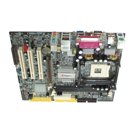
Page 17: Motherboard Map
Motherboard Map Realtek Ethernet PHY PC99 Colored Back Panel CD-IN Connector S/PDIF Connector AC’97 CODEC FAN3 Connector Front Audio Connector MODEM-IN Connector 4-pin 12V. ATX Power Connector COM2 Connector CNR Slot Low ESR Capacitors AGP 4x Expansion Slot 478-pin CPU socket (Willamette/ Northwood) with Voltage and 32-bit PCI Expansion Slot x3 Frequency Auto-detection that... -
Page 18: Block Diagram
PC-2100/2700 SDRAM Up to 2GB 32-bit PCI Slot x3 DIMM Socket x2 Socket 478 533MHz System Intel Pentium 4 CPU(Willamette /Northwood) PCI Bus SIS 651 Primary 66/100/133 Channel IDE Drive x4 Secondary AGP 4X Slot Channel RealTek AC97 962/962L CODEC Realtek lan LAN connect Component USB Channel... -
Page 19: Hardware Installation
This chapter describes jumpers, connectors and hardware devices of this motherboard. This chapter describes jumpers, connectors and hardware devices of this motherboard. Note: Electrostatic discharge (ESD) can damage your processor, disk drives, expansion boards, and other components. Always observe the following precautions before you install a system component. Do not remove a component from its protective packaging until you are ready to install it. -
Page 20: About "User Upgrade Optional" And "Manufacture Upgrade Optional
When you read this online manual and start to assemble your computer system, you may notice that some of the functions are marked as “User Upgrade Optional” or “Manufacture Upgrade Optional”. Although all of AOpen’s motherboards have included many amazing and “User Upgrade Optional”... -
Page 21: Jp14 Clear Cmos Data
You can clear CMOS to restore system default setting. To clear CMOS, follow the procedure below. Turn off the system and unplug the AC power. Remove ATX power cable from connector PWR2. Locate JP14 and short pins 2-3 for a few seconds. Return JP14 to its normal setting by shorting pin 1 &... -
Page 22: Cpu Installation
® ® This motherboard supports Intel This motherboard supports Intel Pentium 4 Socket 478 series CPU (Willamette / Northwood). Be careful of CPU orientation when you plug Pentium 4 Socket 478 series CPU (Willamette / Northwood). Be careful of CPU orientation when you plug it into CPU socket. - Page 23 3. Press down the CPU socket lever and finish CPU installation. CPU cut edge Note: If you do not match the CPU socket Pin 1 and CPU cut edge well, you may damage the CPU. Note: This socket supports Micro-FC-PGA2 package CPU, which is the latest CPU package developed by Intel.
- Page 24 This motherboard comes with a retention module attached on the CPU socket when shipped, we strongly recommend you to install AOpen special designed CPU Fan as shown below on the retention module for better heat dissipation. Please install the CPU Fan correctly as the following pictures shown.
-
Page 25: Cpu Jumper-Less Design
CPU VID signal and CPU VID signal and SMbus SMbus clock generator provide CPU voltage auto-detection and allows the user to set the CPU frequency through the BIOS setup, therefore no jumpers or switches are used. The disadvantages of the Pentium based jumper-less designs are eliminated. There will be no worry of wrong CPU voltage detection. -
Page 26: Setting Cpu Core Voltage
This motherboard supports CPU VID function. The CPU core voltage will be automatically detected. BIOS Setup > Frequency/Voltage Control > CPU Clock Setting This motherboard is CPU jumper-less design, you can set CPU frequency through the BIOS setup, and no jumpers or switches are needed. The default setting is "table select mode". - Page 27 Willamette CPU Core System Northwood CPU Core System Ratio Ratio Frequency Clock Frequency Clock Pentium 4 Pentium 4 1500MHz 100MHz 400MHz 1600MHz 100MHz 400MHz 1.5G 1.6G Pentium 4 Pentium 4 1600MHz 100MHz 400MHz 1600MHz 133MHz 533MHz 1.6G 1.6G Pentium 4 Pentium 4 1700MHz 100MHz...
-
Page 28: Cpu And System Fan Connector (With H/W Monitoring)
Plug in the CPU fan cable to the 3-pin CPU FAN connector. If you have chassis fan, you can also plug it on FAN2 or FAN3 connector. Plug in the CPU fan cable to the 3-pin CPU FAN connector. If you have chassis fan, you can also plug it on FAN2 or FAN3 connector. FAN3 Connector +12V CPU FAN Connector... -
Page 29: Dimm Sockets
This motherboard has two 184-pin DDR DIMM This motherboard has two 184-pin DDR DIMM sockets that allow you to install PC2100 (DDR266) or PC2700 (DDR333) memory up to 2GB. DIMM1 DIMM2... - Page 30 Please follow the procedure as shown below to finish memory installation. Make sure the DIMM module’s pin face down and match the socket’s size as depicted below. Pin 1 52 pins 40 pins Insert the module straight down to the DIMM slot with both hands and press down firmly until the DIMM module is securely in place. Pin 1 Repeat step 2 to finish additional DIMM modules installation.
-
Page 31: Ddr 266(Pc2100) And Ddr 333(Pc2700)
DDR SDRAM utilizes the existing SDRAM infrastructure and technology while doubling the nominal bandwidth available to systems. To put it in a simple way, DDR SDRAM is like data going along a two lane highway, while at the same time data in traditional SDRAM go along a one way street. -
Page 32: Front Panel Connector
Attach the power LED, Keylock, speaker, power and reset switch connectors to the corresponding pins. If you enable “Suspend Mode” item in BIOS Setup, the ACPI & Power LED will keep flashing while the system is in suspend mode. Locate the power switch cable from your ATX housing. It is 2-pin female connector from the housing front panel. -
Page 33: Atx Power Connector
This motherboard comes with a 20-pin and 4-pin ATX power connector. Make sure you plug in the right direction. We strongly recommend This motherboard comes with a 20-pin and 4-pin ATX power connector. Make sure you plug in the right direction. We strongly recommend you to connect the 4-pin 12V ATX connector before connecting the 20-pin ATX power connector and use standard power supply specially you to connect the 4-pin 12V ATX connector before connecting the 20-pin ATX power connector and use standard power supply specially designed for Pentium 4 system. -
Page 34: Ide And Floppy Connector
Connect 34-pin floppy cable and 40-pin IDE cable to floppy connector FDD and IDE connector. Be careful of the pin1 orientation. Wrong orientation may cause system damage. IDE 2 (Secondary) ATA 66/100/133 IDE Connector IDE 1 (Primary) Pin 1 FDD Connector ATA 66/100/133 IDE Connector... - Page 35 IDE1 is also known as the primary channel and IDE2 as the secondary channel. Each channel supports two IDE devices that make a total IDE1 is also known as the primary channel and IDE2 as the secondary channel. Each channel supports two IDE devices that make a total of four devices.
-
Page 36: Ata133 Supported
This motherboard supports This motherboard supports ATA66, ATA66 ATA100 ATA133 IDE devices. Following table lists the transfer rate of IDE PIO and DMA modes. The IDE bus is 16-bit, which means every transfer is two bytes. As the hard drive industry introduces faster and higher capacity hard drives, the current Ultra ATA/100 interface causes a data bottleneck between the drive and the host computer. -
Page 37: Irda Connector
The IrDA connector can be configured to support wireless infrared module, with this module and application software such as Laplink or Windows 95 Direct Cable Connection, the user can transfer files to or from laptops, notebooks, PDA devices and printers. This connector supports HPSIR (115.2Kbps, 2 meters) and ASK-IR (56Kbps). -
Page 38: Agp (Accelerated Graphic Port) Expansion Slot
MX46-533V / MX46-533 Max provides an MX46-533V / MX46-533 Max provides an 4x slot. The AGP 4x is a bus interface targeted for high-performance 3D graphic. AGP supports only memory read/write operation and single-master single-slave one-to-one only. AGP uses both rising and falling edge of the 66MHz clock, for 2X AGP, the data transfer rate is 66MHz x 4bytes x 2 = 528MB/s. -
Page 39: Wol (Wake On Lan)
To use Wake On LAN function, you must have a network card with chipset that supports this feature, and connect a cable from LAN card to To use Wake On LAN function, you must have a network card with chipset that supports this feature, and connect a cable from LAN card to motherboard WOL connector. - Page 40 WOL Connector (Ethernet Card Side) WOL Connector (Motherboard Side) Note: This picture is for example only; it may not exactly look the same with the motherboard you purchased. Note: This picture is for example only; it may not exactly look the same with the motherboard you purchased.
-
Page 41: Support 10/100 Mbps Lan Onboard
On the strength of intergrated SIS LAN controller with Realtek LAN PHY on board, it provides 10/100M bps Ethernet for office and home use. The Ethernet RJ45 connector is located on top of USB connectors. The green LED indicates the linkmode, it lights when linking to network and blinking when transferring data. -
Page 42: Pc99 Color Coded Back Panel
The onboard I/O devices are PS/2 Keyboard, PS/2 Mouse, RJ-45 LAN Connector, COM1 and VGA, Printer, The onboard I/O devices are PS/2 Keyboard, PS/2 Mouse, RJ-45 LAN Connector, COM1 and VGA, Printer, and AC97 sound. The view angle of drawing shown here is from the back panel of the housing. SPP/EPP/ECP RJ-45 LAN Parallel Port... -
Page 43: Support Three Usb2.0 Channels (Six Ports)
This motherboard provides 6 This motherboard provides 6 USB2.0 ports to connect USB devices such as mouse, keyboard, modem, printer, etc. There are four ports on the PC99 back panel. You can use proper cables to connect USB devices from PC99 back panel or connect 3 USB channel header to the front panel of chassis. -
Page 44: Jp28 Usb Keyboard/Mouse Wake-Up Enable/Disable Jumper
This motherboard provides keyboard / mouse wake-up function. You can use JP28 to enable or disable this function, which could resume your system from suspend mode with keyboard or mouse installed. JP28 controls both 1 and 2 USB channel and PS2 port. The factory default setting is set to “Disable”(1-2), and you may enable this function by setting the jumper to 2-3. -
Page 45: Onboard Ieee 1394 Connectors (Mx46-533 Max Only)
This motherboard has two IEEE 1394 connectors onboard. The IEEE 1394 provides data transfer rate up to 400Mb/s, and USB just has 12Mb/s. Therefore the IEEE 1394 interface can connect with the devices that need high data transferring performance, such as digital camera, scanner or others IEEE 1394 devices. -
Page 46: Chassis Intrusion Connector
The “CASE OPEN” header provides chassis intrusion-monitoring function. To make this function works, you have to enable it in the system BIOS, connect this header to a sensor somewhere on the chassis. So, whenever the sensor is triggered by lights or by the opening of the chassis, the system will beep to inform you. -
Page 47: Cd Audio Connector
This connector is used to connect CD Audio cable from CDROM or DVD drive to onboard sound. Note: Though some of the latest versions of Windows support “Digital Audio” through IDE bus. However, in order to use Open Jukebox player, which is driven under CD-IN BIOS, it is a MUST to connect audio cable to CD-IN connector on the motherboard. -
Page 48: Modem-In Connector
The MODEM-CN connector is used to connect Mono In/ Mic Out cable from internal modem card to onboard sound circuit. The MODEM-CN connector is used to connect Mono In/ Mic Out cable from internal modem card to onboard sound circuit. MIC OUT MONO IN MODEM-CN Connector... -
Page 49: Com2 Connector
This motherboard provides two serial ports. One of them are on back panel connector, the other is on the middle left between PCI slots. With proper cable, you can connect it to the back panel of chassis. Pin 1 DCD# SOUT DTR# DSR#... -
Page 50: Front Audio Connector
If the housing has been designed with an audio port on the front panel, you’ll be able to connect onboard audio to front panel through this If the housing has been designed with an audio port on the front panel, you’ll be able to connect onboard audio to front panel through this connector. -
Page 51: S/Pdif (Sony/Philips Digital Interface) Connector
S/PDIF (Sony/Philips Digital Interface) is a latest audio transfer file format that provides impressive quality through optical fiber and allows you to enjoy digital audio instead of analog. Normally there are two S/PDIF outputs as shown, one for RCA connector, the most common one used for consumer audio products, and the other for optical connector with a even better audio quality. -
Page 52: Battery-Less And Long Life Design
This Motherboard implements a This Motherboard implements a Flash ROM Flash ROM and a special circuit that provide you no batter power consumption of current CPU and CMOS Setup configurations. The RTC (real time clock) can also keep running as long as the power cord is plugged. If you lose your CMOS data by accident, you can just reload the CMOS configurations from Flash ROM and the system will recover as usual. -
Page 53: Over-Current Protection
CPU, memory, HDD or add-on cards installed on this motherboard is damaged due to component failure, human operating error or other unknown natural reasons. AOpen cannot guarantee that the protection circuit will always work perfectly. -
Page 54: Hardware Monitoring
(if having this function and enabled) to warn the user. external speaker or buzzer of motherboard (if having this function and enabled) to warn the user. Fan Speed AOpen H/W Monitoring Detection Utility Circuit... -
Page 55: Resettable Fuse
Traditional motherboard uses fuses to prevent Keyboard and Traditional motherboard uses fuses to prevent Keyboard and port from over-current or shortage. These fuses are soldered onboard that when it is broken (function to protect motherboard), user cannot replace them and result in malfunction of motherboard. With expensive Resettable Fuse, the motherboard can be resumed back to normal function even after the fuse had done its protection job. -
Page 56: Low Esr Capacitor
The quality of low ESR capacitor (Low Equivalent Series Resistance) during high frequency operation is very important for the stability of CPU power. The idea of where to put these capacitors is another know-how that requires experience and detail calculation. Not only that, MX46-533V / MX46-533 Max implements 2200μF capacitors, which is much larger than normal capacitor (1000 &... - Page 57 The power circuit of the CPU core voltage must be checked to ensure system stability for high speed CPUs (such as the new Pentium III, or when overclocking). A typical CPU core voltage is 2.0V, so a good design should control voltage between 1.860V and 2.140V. That is, the transient must be below 280mV.
-
Page 58: Layout (Frequency Isolation Wall)
CPU are working in stable condition. The layout of this motherboard implements AOpen’s unique design called “Frequency Isolation Wall”. Separating each critical portion of motherboard into regions, where each region operates in a same or similar frequency range, we can avoid cross talk and frequency interference between each region’s operations and... -
Page 59: Enlarged Aluminum Heatsink
Cool down CPU and Chipset are important for system reliability. Enlarged aluminum heat sink provides better heat consumption especially when you are trying to over-clock the CPU. -
Page 60: Driver And Utility
There are motherboard drivers and utilities in There are motherboard drivers and utilities in AOpen Bonus CD AOpen Bonus CD. You don’t need to install all of them to boot your system. But after you finish the hardware installation, you have to install your operation system first (such as Windows 98) before you install any drivers or utilities. -
Page 61: Auto-Run Menu From Bonus Cd
You can use the auto-run menu of Bonus CD. Choose the utility and driver and select model name. -
Page 62: Install Ide Driver
To use IDE devices you have to install IDE driver from Bonus Pack CD. -
Page 63: Installing Agp Driver
You can find AGP driver from the Bonus Pack CD auto-run menu. -
Page 64: Installing Vga Driver
SiS 651 supports VGA on this motherboard. You can install VGA driver form the Bonus Pack CD. -
Page 65: Install Usb2.0 Driver
In Bonus Pack CD, you can install USB2.0 driver from the following screen. -
Page 66: Installing Lan Driver
You can download LAN Driver from the Bonus Pack CD and install it under Windows 95 (Golden version), Win95A, OSR2, Windows 98/98 SE, Windows 2000, Windows ME, Windows NT v4.0 driver for Realtek RTL8201 PCI Fast Ethernet adapter. [Windows 95 (Golden version), Win95A and OSR2] Installing driver procedure on Microsoft Windows 95 : ----------------------------------------------------- 1. - Page 67 [CD-ROM]:Driver\LAN\RTL8100\Windows\WIN2000 (for Windows 2000) or [CD-ROM]:Driver\LAN\RTL8100\Windows\WINME (for Windows ME) or [CD-ROM]:Driver\LAN\RTL8100\Windows\WinXP (for Windows XP) 3. Win98/Win98 SE/Windows2000/Windows ME will appear some messages to insert Win98/Win98 SE/Windows2000/Windows ME system disk to complete setup step. 4. Win98/Win98 SE/Windows2000/Windows ME will finish the other installation procedure automatically, then you restart the system. [Windows NT 3.5, 3.51 &...
- Page 68 RTL8139 PCI Fast Ethernet adapter and its driver RTL8139.SYS will auto-detect the line speed, 10 Mb or 100Mb, while the RTL8139.SYS is loading. The other values, "10" or "100", are only used when you want to forced RTL8139 PCI Fast Ethernet adapter to 10Mb or 100Mb. 7.
-
Page 69: Installing Onboard Sound Driver
This motherboard comes with AC97 CODEC. This audio driver supports Windows 98SE and upper Windows OS; you can find the audio driver from the Bonus Pack CD auto-run menu. -
Page 70: Aoconfig Utility
Moreover, AOConfig allows users to save information in *.BMP or *.TXT format which users may collect the system information in detail and send them to AOpen directly for technical support or for further diagnose of system problems. 1. The system page shows the... - Page 71 NOTE: AOConfig can be used under Windows 98SE/ME, NT4.0/2000, or even the latest Windows XP. Please also note that AOConfig can only be operated in a system equipped with an AOpen motherboard. Before running AOConfig, all applications must be closed.
-
Page 72: Installing Hardware Monitoring Utility
You can install Hardware Monitoring Utility to monitor CPU temperature, fans and system voltage. The hardware monitoring function is automatically implemented by BIOS and utility software. No hardware installation is needed. -
Page 73: Acpi Suspend To Hard Drive
ACPI ACPI Suspend to Hard Drive is basically controlled by Windows operation system. It saves your current work (system status, memory and screen image) into hard disk, and then the system can be totally power off. Next time, when power is on, you can resume your original work directly from hard disk within few seconds without go through the Windows booting process and run your application again. -
Page 74: System Requirement
System Requirement AOZVHDD.EXE 1.30b or later. Delete config.sys and autoexec.bat. Fresh installation of Windows 98 on a new system 1. Execute "Setup.exe /p j" to install Windows 98 2. After Windows 98's installation is complete, go to the Control Panel > Power Management. a. - Page 75 Changing from APM to ACPI (Windows 98 only) 1. Run "Regedit.exe" a. Go through the following path HKEY_LOCAL_MACHINE SOFTWARE MICROSOFT WINDOWS CURRENT VERSION DETECT b. Select "ADD Binary" and name it as "ACPIOPTION". c. Right click and select Modify, add "01" after "0000" to make it "0000 01". d.
- Page 76 HKEY_LOCAL_MACHINE HKEY_LOCAL_MACHINE SOFTWARE SOFTWARE MICROSOFT MICROSOFT WINDOWS WINDOWS CURRENT VERSION CURRENT VERSION DETECT DETECT ACPI OPTION ACPI OPTION b. Right click and select "Modify, change "01" to "02" to make it "0000 02". b. Right click and select "Modify, change "01" to "02" to make it "0000 02". Tip: "02"...
-
Page 77: Acpi Suspend To Ram (Str)
This motherboard supports This motherboard supports ACPI ACPI Suspend to RAM function. With this function, you can resume your original work directly from DRAM without going through the Windows 98 booting process and run your application again. Suspend to DRAM saves your current work in the system memory, it is faster than Suspend to Hard Drive but requires power supplied to DRAM, while Suspend to Hard Drive requires no power. - Page 78 To implement ACPI Suspend to DRAM, please follow the procedures as below: System Requirement An ACPI OS is required. Currently, except Windows 95 and Windows NT, all other Windows Systems support ACPI. Procedures Changed the following BIOS settings. BIOS Setup > Power Management Setup > ACPI Function: Enabled BIOS Setup >...
-
Page 79: Award Bios
Most BIOS settings of MX46-533V / MX46-533 Max have been optimized by AOpen’s R&D engineering team. But, the default setting of BIOS still can’t fine-tune the chipset controlling entire system. Therefore, the rest of this chapter intends to guide you the process of configuring your system setup. -
Page 80: About Bios Function Description
… AOpen always dedicates to give user a more friendly computer system. Now, we include all function descriptions of BIOS setup program AOpen always dedicates to give user a more friendly computer system. Now, we include all function descriptions of BIOS setup program into the BIOS Flash ROM. -
Page 81: How To Use Award™ Bios Setup Program
The following table provides details about how to use keyboard in the Award™ BIOS setup program. By the way, all products of AOpen also provide a special function in BIOS setup; you can press <F3> key selecting you preferred menu language. - Page 82 Description Load fail-save setting value from CMOS. Load turbo setting value from CMOS. Save changed setting and exit setup program.
-
Page 83: How To Enter Bios Setup
After you finish jumper settings and connect correct cables, power on and enter the BIOS Setup. Press <Del> during POST (Power-On Self Test) and choose "Load Setup Defaults" for recommended optimal performance. Warning: Please avoid of using "Load Turbo Defaults", unless you are sure your system components (CPU, DRAM, HDD, etc.) are good enough for turbo setting. -
Page 84: Bios Upgrade Under Windows Environment
Windows 95/98, 98SE/ME, NT4.0/2000, or even the latest Windows XP. In the meanwhile, in order to provide a much more user-friendly operating environment, AOpen EZWinFlash is natively designed to have multi-language function to provide easier way for users’... - Page 85 1. Download the new version of BIOS package 1. Download the new version of BIOS package file from AOpen official web site. (ex: http://www.aopen.com) 2. Unzip the download BIOS package (ex: WMX46533V102.ZIP) with WinZip (http://www.winzip.com) in Windows environment. 3. Save the unzipped files into a folder, for example, WMX46533V102.EXE & WMX46533V102.BIN.
-
Page 86: Overclocking
As a leading manufacturer in motherboard industry, AOpen always listens to what customers want and develop products to fit different As a leading manufacturer in motherboard industry, AOpen always listens to what customers want and develop products to fit different user's requirements. -
Page 87: Vga Card & Hard Disk
VGA and HDD is key components for overclocking, for your reference, the following list are what have been successful overclocked in our lab. Please note that AOpen can not guaranty they can be successful overclocked again. Please check the Available Vendor List (AVL) by link to our official website. -
Page 88: Glossary
AGP uses both rising and falling edge of the 66MHz clock, for 2X AGP, the data transfer rate is 66MHz x 4byte x 2 = 528MB/s. AGP is now moving to 4X mode, 66MHz x 4byte x 4 = 1056MB/s. AOpen is the first company to support 4X AGP... -
Page 89: Amr (Audio/Modem Riser)
Unlike ACPI, BIOS controls most APM power management functions. AOpen Suspend to Hard Drive is a good example of APM power management. ATA is the specification of diskette interface. In 80’s, many software and hardware manufacturers instituted the ATA specification together. -
Page 90: Ata/100
ATA/100 is a new IDE specification under developing. ATA/100 uses both rising edge and falling edge as ATA/66 but clock cycle time is reduced to 40ns. The data transfer rate is (1/40ns) x 2 bytes x 2 = 100MB/s. To use ATA/100, you need special 80-wire IDE cable, the same as ATA/66. -
Page 91: Codec (Coding And Decoding)
Normally, CODEC means a circuit that can do digital to analog conversion and also the analog to digital conversion. It is part of AC97 sound/modem solution. DDR SDRAM utilizes the existing DRAM infrastructure and technology while doubling the nominal bandwidth available to systems in an easy to design and simple to adopt way. -
Page 92: Ecc (Error Checking And Correction)
The ECC mode needs 8 ECC bits for 64-bit data. Each time memory is accessed; ECC bits are updated and checked by a special algorithm. The ECC algorithm has the ability to detect double-bit error and automatically correct single-bit error while parity mode can only detect single-bit error. -
Page 93: Ev6 Bus
Flash ROM can be re-programmed by electronic signals. It is easier for BIOS to upgrade by a flash utility, but it is also easier to be infected by virus. Because of increase of new functions, BIOS size is increased from 64KB to 256KB (2M bit). AOpen AX5T is the first board to implement 256KB (2Mbit) Flash ROM. -
Page 94: Fsb (Front Side Bus) Clock
FSB Clock means CPU external bus clock. CPU internal clock = CPU FSB Clock x CPU Clock Ratio See SMBus. IEEE 1394 is a low-cost digital interface originated by Apple Computer as a desktop LAN and developed by the IEEE 1394 working group. The IEEE 1394 can transport data at 100, 200 or 400 Mbps. -
Page 95: Pbsram (Pipelined Burst Sram)
For Socket 7 CPU, one burst data read requires four QWord (Quad-word, 4x16 = 64 bits). PBSRAM only needs one address decoding time and automatically sends the remaining QWords to CPU according to a predefined sequence. Normally, it is 3-1-1-1, total 6 clocks, which is faster than asynchronous SRAM. -
Page 96: Pdf Format
A file format for electronic document, PDF format is independent from platform, you can read PDF file under Windows, Unix, Linux, Mac … with different PDF reader. You can also read PDF file by web browser such as IE and Netscape, note that you need to install PDF plug-in first (Included in Acrobat Reader). -
Page 97: Rimm (Rambus Inline Memory Module)
SDRAM comes in 64-bit 168-pin DIMM and operates at 3.3V. AOpen is the first company to support dual-SDRAM DIMMs onboard (AP5V), from Q1 1996 A memory space in Flash-ROM to simulate E PROM operation, AOpen motherboard uses Shadow E... -
Page 98: Smbus (System Management Bus)
SMBus is also called I2C bus. It is a two-wire bus developed for component communication (especially for semiconductor IC). For example, set clock of clock generator for jumper-less motherboard. The data transfer rate of SMBus is only 100Kbit/s, it allows one host to communicate with CPU and many masters and slaves to send/receive message. -
Page 99: Usb (Universal Serial Bus)
USB is a 4-pin serial peripheral bus that is capable of cascading low/medium speed peripherals (less than 10Mbit/s) such as keyboard, mouse, joystick, scanner, printer and modem. With USB, the traditional complex cables from back panel of your PC can be eliminated. NEC’s Virtual Channel Memory (VCM) is a new DRAM core architecture that dramatically improves the memory system’s ability to service multimedia requirements. -
Page 100: Troubleshooting
If you encounter any trouble to boot you system, follow the procedures accordingly to resolve the problem. Start Turn off the power and unplug the AC power cable, then remove all of the add-on cards and cables, including VGA, IDE, FDD, COM1, COM2 and printer. Make sure if all jumper settings are correct. - Page 101 Continue Install the VGA card. Then connect your monitor and keyboard. Turn on the power and check if the power supply and CPU fan work properly. The problem is probably caused by power supply or motherboard failure Next Please contact your reseller or local distributor for repairing.
- Page 102 Continue Perhaps your VGA card Check if there is display? Check if there is display? or monitor is defective. Press <Ctrl> and <Alt> key at the same time, hold them and then press <Del> to reboot the system. It is very possible that your Check if the system keyboard iskeyboard is defective.
- Page 103 Continue During system rebooting, press <Del> to enter BIOS setup Choose “Load Setup Default”. Turn off the system and re-connect IDE cable. The problem should be Check if the system can caused by the IDE cable reboot successfully? or HDD itself Re-install the operating system such as Windows 98.
-
Page 104: Technical Support
Dear Customer, Thanks for choosing AOpen products. To provide the best and fastest service to our customer is our first priority. However, we receive numerous emails and phone-calls worldwide everyday, it is very hard for us to serve everyone on time. We recommend you follow the procedures below and seek help before contact us. - Page 105 News Group: Your problem probably had been answered by our support engineer or professional users on the news group. http://www.aopen.com/tech/newsgrp/default.htm Contact Distributors/Resellers: We sell our products through resellers and integrators. They should know your system configuration very well and should be able to solve your problem efficiently and provide important reference for you if next time you want to buy something else from them.
- Page 106 Model name and BIOS version can be found on upper left corner of first boot screen (POST (POST screen). For example: MX46533V R1.20 Aug.01.2002 AOpen Inc. Award Plug and Play BIOS Extension v1.0A Copyright © 2002, Award Software, Inc. MX46533V is model name of motherboard; R1.20 is BIOS version.
- Page 107 Be able to join the discussions of web-based news groups. AOpen makes sure that the information you provide is encrypted, so that it cannot be read or intercepted by other people or companies. AOpen makes sure that the information you provide is encrypted, so that it cannot be read or intercepted by other people or companies.
- Page 108 Please do not hesitate contact us if you have any problem about our products. Any opinion will be appreciated. Please do not hesitate contact us if you have any problem about our products. Any opinion will be appreciated. Pacific Rim Europe America AOpen Inc. AOpen Computer b.v. AOpen America Inc. Tel: 886-2-3789-5888 Tel: 31-73-645-9516 Tel: 1-510-489-8928 Fax: 886-2-3789-5899...
Need help?
Do you have a question about the MX46-533 Max and is the answer not in the manual?
Questions and answers