Advertisement
Advertisement
Table of Contents

Related Manuals for Asus PTGD1-LA Puffer M-UL8E


Summary of Contents for Asus PTGD1-LA Puffer M-UL8E
- Page 1 PTGD1-LA (Puffer M-UL8E)
-
Page 2: Table Of Contents
Contents PTGD1-LA specifications summary ............. iii Motherboard layout ..............1 Central Processing Unit (CPU) ..........2 System memory ..............5 Expansion slots ................ 8 Jumpers ................. 10 Connectors ................11 Rear panel connectors ..........11 Internal connectors ..........13... -
Page 3: Ptgd1-La Specifications Summary
PTGD1-LA specifications summary C P U C P U C P U LGA775 socket for the Intel ® Pentium ® 4 processor C P U C P U C h i p s e t C h i p s e t C h i p s e t Nortbridge: Intel ®... - Page 4 P C h e a l t h P C h e a l t h ASUS A8000 for CPU, system, and chassis fan m o n i t o r i n g m o n i t o r i n g...
-
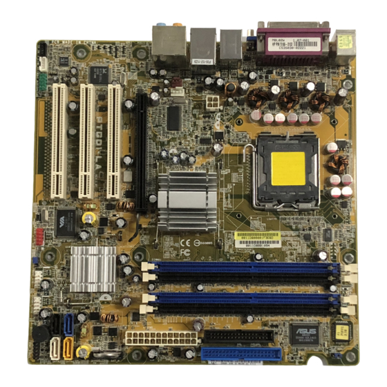
Page 5: Motherboard Layout
Motherboard layout 24.5cm (9.6in) PS/2KBMS 4Mbit T: Mouse Flash B: Keyboard CLPWD ASUS A8000 Bottom: Top: T:USB1 1394 B:USB2 USB2.0 Top: Intel T: USB3 ATX12V RJ-45 B: USB4 915P Top: Subwoofer Speaker Out Center AUDIO Rear Speaker Out Top:Line In... -
Page 6: Central Processing Unit (Cpu)
Contact your retailer immediately if the PnP cap is missing, or if you see any damage to the PnP cap/socket contacts/motherboard components. ASUS will shoulder the cost of repair only if the damage is shipment/ transit-related. •... - Page 7 Press the load lever with your thumb (A), then move it to the left (B) until it is released from the retention tab. R e t e n t i o n t a b R e t e n t i o n t a b R e t e n t i o n t a b R e t e n t i o n t a b R e t e n t i o n t a b...
- Page 8 Close the load plate (A), then push the load lever (B) until it snaps into the retention tab. The CPU fits in only one correct orientation. DO NOT force the CPU into the socket to prevent bending the connectors on the socket and damaging the CPU! Notes on Intel Notes on Intel...
-
Page 9: System Memory
System memory The motherboard comes with four Double Data Rate (DDR) Dual Inline Memory Module (DIMM) sockets. The following figure illustrates the location of the DDR DIMM sockets. PTGD-LA PTGD1-LA 184-pin DDR DIMM sockets Memory configurations Memory configurations Memory configurations Memory configurations Memory configurations You can install 128 MB, 256 MB, 512 MB, and 1GB DDR SDRAM DIMMs into... - Page 10 Recommended memory configurations Recommended memory configurations Recommended memory configurations Recommended memory configurations Recommended memory configurations S o c k e t s S o c k e t s S o c k e t s S o c k e t s S o c k e t s M o d e M o d e...
- Page 11 3 . 2 3 . 2 Installing a DDR DIMM Installing a DDR DIMM 3 . 2 3 . 2 3 . 2 Installing a DDR DIMM Installing a DDR DIMM Installing a DDR DIMM Make sure to unplug the power supply before adding or removing DIMMs or other system components.
-
Page 12: Expansion Slots
Expansion slots The motherboard has one PCI Express and three PCI slots. To install and configure an expansion card: Install an expansion card following the instructions that came with the chassis. Turn on the system and change the necessary BIOS settings, if any. Assign an IRQ to the card. - Page 13 IRQ assignments for this motherboard IRQ assignments for this motherboard IRQ assignments for this motherboard IRQ assignments for this motherboard IRQ assignments for this motherboard PCI slot 1 — — — shared — — PCI slot 2 shared — — —...
-
Page 14: Jumpers
Jumpers Clear RTC RAM (3-pin CLRTC) Clear RTC RAM (3-pin CLRTC) Clear RTC RAM (3-pin CLRTC) Clear RTC RAM (3-pin CLRTC) Clear RTC RAM (3-pin CLRTC) This jumper allows you to clear the Real Time Clock (RTC) RAM in CMOS. You can clear the CMOS memory of date, time, and system setup parameters by erasing the CMOS RTC RAM data. -
Page 15: Connectors
Connectors 6 . 1 6 . 1 Rear panel connectors Rear panel connectors 6 . 1 6 . 1 6 . 1 Rear panel connectors Rear panel connectors Rear panel connectors 1 . 1 . P S / 2 m o u s e p o r t ( g r e e n ) . P S / 2 m o u s e p o r t ( g r e e n ) . - Page 16 Audio 2, 4, 6, or 8-channel configuration Audio 2, 4, 6, or 8-channel configuration Audio 2, 4, 6, or 8-channel configuration Audio 2, 4, 6, or 8-channel configuration Audio 2, 4, 6, or 8-channel configuration H e a d s e t / H e a d s e t / H e a d s e t / H e a d s e t /...
-
Page 17: Internal Connectors
6 . 2 6 . 2 6 . 2 6 . 2 6 . 2 Internal connectors Internal connectors Internal connectors Internal connectors Internal connectors This section describes and illustrates the internal connectors on the motherboard. 1 . 1 . F l o p p y d i s k d r i v e c o n n e c t o r ( 3 4 - 1 p i n F L O P P Y ) F l o p p y d i s k d r i v e c o n n e c t o r ( 3 4 - 1 p i n F L O P P Y ) F l o p p y d i s k d r i v e c o n n e c t o r ( 3 4 - 1 p i n F L O P P Y ) - Page 18 2 . 2 . I D E c o n n e c t o r ( 4 0 - 1 p i n I D E ) I D E c o n n e c t o r ( 4 0 - 1 p i n I D E ) I D E c o n n e c t o r ( 4 0 - 1 p i n I D E ) I D E c o n n e c t o r ( 4 0 - 1 p i n I D E ) I D E c o n n e c t o r ( 4 0 - 1 p i n I D E )
- Page 19 3 . 3 . A T X p o w e r c o n n e c t o r s ( 2 4 - p i n A T X P W R , 4 - p i n A T X 1 2 V ) A T X p o w e r c o n n e c t o r s ( 2 4 - p i n A T X P W R , 4 - p i n A T X 1 2 V ) A T X p o w e r c o n n e c t o r s ( 2 4 - p i n A T X P W R , 4 - p i n A T X 1 2 V ) A T X p o w e r c o n n e c t o r s ( 2 4 - p i n A T X P W R , 4 - p i n A T X 1 2 V )
-
Page 20: Hard Disk Drives
4 . 4 . S S S S S e r i a l A T A c o n n e c t o r s e r i a l A T A c o n n e c t o r s e r i a l A T A c o n n e c t o r s e r i a l A T A c o n n e c t o r s e r i a l A T A c o n n e c t o r s... - Page 21 5 . 5 . I E E E 1 3 9 4 a c o n n e c t o r ( 1 0 - 1 p i n F R O N T _ 1 3 9 4 ) I E E E 1 3 9 4 a c o n n e c t o r ( 1 0 - 1 p i n F R O N T _ 1 3 9 4 ) I E E E 1 3 9 4 a c o n n e c t o r ( 1 0 - 1 p i n F R O N T _ 1 3 9 4 ) I E E E 1 3 9 4 a c o n n e c t o r ( 1 0 - 1 p i n F R O N T _ 1 3 9 4 )
- Page 22 7 . 7 . C P U a n d S y s t e m f a n c o n n e c t o r s C P U a n d S y s t e m f a n c o n n e c t o r s C P U a n d S y s t e m f a n c o n n e c t o r s C P U a n d S y s t e m f a n c o n n e c t o r s C P U a n d S y s t e m f a n c o n n e c t o r s...
- Page 23 9 . F r o n t h e a d p h o n e c o n n e c t o r ( 1 0 - 1 p i n F R O N T _ A U D I O ) 9 .
- Page 24 1 0 . 1 0 . 1 0 . S y s t e m p a n e l c o n n e c t o r ( 1 0 - 1 p i n F R O N T _ P A N E L ) S y s t e m p a n e l c o n n e c t o r ( 1 0 - 1 p i n F R O N T _ P A N E L ) S y s t e m p a n e l c o n n e c t o r ( 1 0 - 1 p i n F R O N T _ P A N E L ) S y s t e m p a n e l c o n n e c t o r ( 1 0 - 1 p i n F R O N T _ P A N E L )
Need help?
Do you have a question about the PTGD1-LA Puffer M-UL8E and is the answer not in the manual?
Questions and answers