Table of Contents
Advertisement
Advertisement
Table of Contents

Related Manuals for Asus Striker II Formula


Summary of Contents for Asus Striker II Formula
- Page 1 Striker II Formula...
- Page 2 Product warranty or service will not be extended if: (1) the product is repaired, modified or altered, unless such repair, modification of alteration is authorized in writing by ASUS; or (2) the serial number of the product is defaced or missing.
-
Page 3: Table Of Contents
Product highlights ............1-2 1.3.2 ROG Intelligent Performance & Overclocking features ... 1-5 1.3.3 ROG unique features ............1-7 1.3.4 ASUS special features ............ 1-8 Chapter 2: Hardware information Before you proceed ..............2-1 Motherboard overview ..............2-4 2.2.1 Placement direction ............2-4 2.2.2... -
Page 4: Contents
Chapter 4: BIOS setup Managing and updating your BIOS ..........4-1 4.1.1 ASUS Update utility ............4-1 4.1.2 ASUS EZ Flash 2 utility ........... 4-4 4.1.3 Updating the BIOS ............4-5 4.1.4 Saving the current BIOS file ..........4-7 4.1.5 ASUS CrashFree BIOS 2 utility ........ - Page 5 Contents 4.3.1 System Time ..............4-13 4.3.2 System Date ..............4-13 4.3.3 Language ..............4-13 4.3.4 Legacy Diskette A ............4-13 4.3.5 Primary IDE Master/Slave ..........4-14 4.3.6 SATA 1–6 ..................4-16 4.3.7 HDD SMART Monitoring ..........4-17 4.3.8 Installed Memory ............4-17 4.3.9 Usable Memory .............
- Page 6 ® 5.3.4 ASUS PC Probe II ............5-21 5.3.5 ASUS AI Suite ............... 5-27 5.3.6 ASUS EPU Utility—AI Gear 3 ........5-29 5.3.7 ASUS AI Nap ..............5-30 5.3.8 ASUS Q-Fan 2 .............. 5-31 5.3.9 ASUS AI Booster ............5-32 5.3.10...
- Page 7 Contents 5.5.2 Creating a RAID/SATA driver disk in Windows .... 5-42 ® Chapter 6: NVIDIA SLI™ technology support ® Overview ..................6-1 Requirements ................. 6-1 Graphics card setup ..............6-2 6.2.1 Installing three SLI-ready graphics cards ......6-2 6.2.2 Installing two SLI-ready graphics cards ......6-5 6.2.3 Installing the device drivers ..........
-
Page 8: Notices
Notices Federal Communications Commission Statement This device complies with Part 15 of the FCC Rules. Operation is subject to the following two conditions: • This device may not cause harmful interference, and • This device must accept any interference received including interference that may cause undesired operation. -
Page 9: Safety Information
Safety information Electrical safety • To prevent electrical shock hazard, disconnect the power cable from the electrical outlet before relocating the system. • When adding or removing devices to or from the system, ensure that the power cables for the devices are unplugged before the signal cables are connected. -
Page 10: About This Guide
Refer to the following sources for additional information and for product and software updates. ASUS websites The ASUS website provides updated information on ASUS hardware and software products. Refer to the ASUS contact information. Optional documentation Your product package may include optional documentation, such as warranty flyers, that may have been added by your dealer. -
Page 11: Conventions Used In This Guide
Conventions used in this guide To make sure that you perform certain tasks properly, take note of the following symbols used throughout this manual. DANGER/WARNING: Information to prevent injury to yourself when trying to complete a task. CAUTION: Information to prevent damage to the components when trying to complete a task. -
Page 12: Stricker Ii Formula Specifications Summary
® ® Supports Intel next-generation 45nm multi-core CPUs ® Compatible with Intel 06/05B/05A processors 06/05B/05A processors 05B/05A processors ® * Refer to www.asus.com for Intel CPU support list Chipset NVIDIA nForce 780i SLI™ ® ® System Bus 1333/1066/800 MHz Memory... - Page 13 2-Phase DDR2 ROG BIOS Wallpaper Loadline Calibration Intelligent overclocking tools: - CPU Level Up - ASUS EPU (Energy Processing Unit) - AI Gear 3 - AI Overclocking (intelligent CPU frequency tuner) - AI Booster Utility � O.C. Profile Overclocking protection:...
- Page 14 WOL by PME, WOR by PME, Chassis Intrusion, PXE Accessories LCD Poster ASUS Optional Fan SupremeFX II Audio Card 3 in 1 ASUS Q-connector kit UltraDMA 133/100/66 cable Floppy disk drive cable Serial ATA cables Serial ATA power cables 2-port USB2.0 + IEEE 1394a module...
-
Page 15: Chapter 1: Product Introduction
This chapter describes the motherboard features and the new technologies it supports. Chapter 1: Product introduction... - Page 16 Chapter summary Welcome! ..................1-1 Package contents ................. 1-1 Special features ................1-2 ROG Striker II Formula...
-
Page 17: Welcome
® The motherboard delivers a host of new features and latest technologies, making it another standout in the long line of ASUS quality motherboards! Before you start installing the motherboard, and hardware devices on it, check the items in your package with the list below. -
Page 18: Special Features
Special features 1.3.1 Product highlights Republic of Gamers The Republic of Gamers consists only the best of the best. We offer the best hardware engineering, the fastest performance, the most innovating ideas, and we welcome the best gamers to join in. In the Republic of Gamers, mercy rules are only for the weak, and bragging rights means everything. - Page 19 Native DDR2 1066 memory support To attain top performance, ASUS engineers have successfully unleashed the true potential of DDR2 memory. While in DDR2 1066 mode, ASUS’s exclusive technology offers a choice of FSB 1333, providing great performance for 3D graphics and other memory demanding applications. See page 2-17 for details.
- Page 20 Green ASUS This motherboard and its packaging comply with the European Union’s Restriction on the use of Hazardous Substances (RoHS). This is in line with the ASUS vision of creating environment-friendly and recyclable products/packaging to safeguard consumers’ health while minimizing the impact on the environment.
-
Page 21: Rog Intelligent Performance & Overclocking Features
4-19 and 5-33 for details. ASUS EPU The ASUS �PU utilizes innovative technology to digitally monitor and tune the CPU power supply with improved VR responses in heavy or light loadings. It automatically provides power for higher performance or improve efficiency by 7% when the PC is running low intensity applications. - Page 22 The COP EX allows more freedom and less constraint for maximum performance achievement. AI Booster The ASUS AI Booster allows you to overclock the CPU speed in Windows ® environment without the hassle of booting the BIOS. See page 5-32 for details.
-
Page 23: Rog Unique Features
See page 2-42 for details. ASUS Quiet Thermal Solution ASUS Quiet Thermal solution makes system more stable and enhances the overclocking capability. Fanless Design–Heat-pipe The ASUS fanless design allows multi�directional heat flow from major thermal sources in the motherboard to lower overall system temperature, resulting in quieter operation and longer system life. -
Page 24: Asus Special Features
Fanless Design–Stack Cool 2 ASUS Stack Cool 2 is a fan�less and zero�noise cooling solution that lowers the temperature of critical heat generating components. The motherboard uses a special design on the printed circuit board (PCB) to dissipate heat these critical components generate. - Page 25 ASUS MyLogo 3 ASUS MyLogo 3 is a new feature present in the motherboard that allows you to personalize and add style to your system with customizable and animated boot logos. See page 4-43 for details. ASUS Multi-language BIOS The multi-language BIOS allows you to select the language of your choice from the available options.
- Page 26 1-10 Chapter 1: Product Introduction...
-
Page 27: Chapter 2: Hardware Information
This chapter lists the hardware setup procedures that you have to perform when installing system components. It includes description of the jumpers and connectors on the motherboard. Chapter 2: Hardware information... - Page 28 Chapter summary Before you proceed ..............2-1 Motherboard overview ..............2-4 Central Processing Unit (CPU) ........... 2-8 System memory ................. 2-17 Expansion slots ................2-23 Jumper ..................2-27 Aduio card, I/O shield, and LCD Poster Installation ....2-28 Connectors ................. 2-30 ROG Striker II Formula...
-
Page 29: Before You Proceed
Before you proceed Take note of the following precautions before you install motherboard components or change any motherboard settings. • Unplug the power cord from the wall socket before touching any component. • Use a grounded wrist strap or touch a safely grounded object or a metal object, such as the power supply case, before handling components to avoid damaging them due to static electricity. - Page 30 Memory LED Refer to the illustration below for the location of the memory LED and the table below for ���D definition. DDR_CRAZY DDR_HIGH DDR_NORMAL STRIKER II FORMULA ® STRIKER II FORMULA DDR LED Normal (green) High (yellow) Crazy (red) Memory Voltage 1.80~2.20 2.22~2.60 2.62~...
- Page 31 Hard Disk LED The hard disk LED is designed to indicate the hard disk activity. It blinks when data is being written into or read from the hard disk drive. The LED does not light up when there is no hard disk drive connected to the motherboard or when the hard disk drive does not function.
-
Page 32: Motherboard Overview
Motherboard overview Before you install the motherboard, study the configuration of your chassis to ensure that the motherboard fits into it. Make sure to unplug the power cord before installing or removing the motherboard. Failure to do so can cause you physical injury and damage motherboard components. -
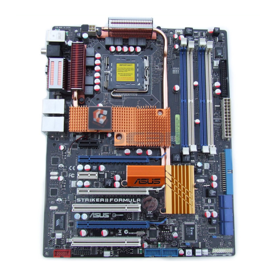
Page 33: Motherboard Layout
2.2.3 Motherboard layout 24.5cm (9.6in) EATX12V CPU_FAN LCD_CON KB_USB56 BIOS SPDIF_O12 LGA775 SPDIF_OUT CLR_CMOS E1394 CPU_CRAZY CPU_HIGH CPU_NORMAL LAN2_USB34 NVIDIA ® LAN1_USB12 nForce ® 780i SLI™ OPT_FAN2 OPT_TEMP2 DDR_CRAZY PCIEX1_1 DDR_HIGH DDR_NORMAL NB_CRAZY NB_HIGH NB_NORMAL PCIEX16_1 88E1116 CHA_FAN3 PCIEX1_2 NVIDIA ®... -
Page 34: Layout Contents
2.2.5 Layout contents Slots Page DDR2 DIMM slots 2-17 PCI slots 2-25 PCI Express x 1 slots 2-25 PCI Express x 16 slots 2-25 Jumper Page Clear RTC RAM (3-pin CLRTC_SW) 2-27 Rear panel connectors Page PS/2 keyboard port (purple) 2-30 Coaxial S/PDIF Out port 2-30... - Page 35 (4-pin CPU_FAN, 3-pin CHA_FAN1–3, 3-pin PWR_FAN, 2- 36 3-pin OPT_FAN1–3) Chassis intrusion connector (4-1 pin CHASSIS) 2- 37 Digital audio connector (4-1 pin SPDIF_OUT, for ASUS HDMI 2- 37 VGA card) ATX power connectors (24-pin EATXPWR, 8-pin EATX12V) 2- 38...
-
Page 36: Central Processing Unit (Cpu)
ASUS will shoulder the cost of repair only if the damage is shipment/transit-related. • Keep the cap after installing the motherboard. ASUS will process Return Merchandise Authorization (RMA) requests only if the motherboard comes with the cap on the LGA775 socket. -
Page 37: Installing The Cpu
2.3.1 Installing the CPU To install a CPU: Locate the CPU socket on the motherboard. STRIKER II FORMULA ® STRIKER II FORMULA CPU Socket 775 Before installing the CPU, make sure that the cam box is facing towards you and the load lever is on your left. Press the load lever with your thumb (A), then move it to the left (B) until it is released from the retention tab. - Page 38 Lift the load plate with your thumb and forefinger to a 100º angle (A), then push the PnP cap from the load plate window to remove (B). Load plate Alignment key Position the CPU over the socket, making sure that the gold triangle is on the bottom-left corner of the socket then fit the socket...
-
Page 39: Installing The Cpu Heatsink And Fan
2.3.2 Installing the CPU heatsink and fan The Intel ® LGA775 processor requires a specially designed heatsink and fan assembly to ensure optimum thermal condition and performance. • When you buy a boxed Intel processor, the package includes the CPU fan ®... - Page 40 Push down two fasteners at a time in a diagonal sequence to secure the heatsink and fan assembly in place. Connect the CPU fan cable to the connector on the motherboard labeled CPU_FAN. CPU_FAN STRIKER II FORMULA ® STRIKER II FORMULA CPU fan connector DO NOT forget to connect the CPU fan connector! Hardware monitoring errors can occur if you fail to plug this connector.
-
Page 41: Uninstalling The Cpu Heatsink And Fan
2.3.3 Uninstalling the CPU heatsink and fan To uninstall the CPU heatsink and fan: Disconnect the CPU fan cable from the connector on the motherboard. Rotate each fastener counterclockwise. Pull up two fasteners at a time in a diagonal sequence to disengage the heatsink and fan assembly from the motherboard. - Page 42 Rotate each fastener clockwise to ensure correct orientation when reinstalling. Narrow end of the groove The narrow end of the groove should point outward after resetting. (The photo shows the groove shaded for emphasis.) Refer to the documentation in the boxed or stand-alone CPU fan package for detailed information on CPU fan installation.
-
Page 43: Installing The Optional Fans
2.3.4 Installing the optional fans Install TWO optional fans when you are using a water cooler to obtain better to obtain better heat dissipation. Installing the optional fans with an active CPU cooler will . Installing the optional fans with an active CPU cooler will interfere with the airflow and destabilize the system. - Page 44 Follow Step 1 to 4 to install the other optional fan. The photo shows that two fans are installed to the motherboard. Plug the optional fan cable in the PWR_FAN connector on the motherboard. 2-16 Chapter 2: Hardware information...
-
Page 45: System Memory
Sockets Channel A DIMM_A1 and DIMM_A2 Channel B DIMM_B1 and DIMM_B2 • This chipset officially supports DDR2�800 MHz. With the ASUS Super Memspeed Technology, this motherboard natively supports up to DDR2�1066 MHz. See the table below. DDR2 1333 1066* 1333... -
Page 46: Memory Configurations
2.4.2 Memory configurations You may install 256 MB, 512 MB, 1 GB, and 2 GB unbuffered non-ECC DDR2 DIMMs into the DIMM sockets. Recommended Memory Configurations Sockets Mode DIMM_A1 DIMM_A2 DIMM_B1 DIMM_B2 Populated – – – Single-Channel – – Populated –... - Page 47 Dual�channel memory configuration. C*: Supports four modules inserted into both the blue and white slots • as two pairs of Dual�channel memory configuration. �isit the ASUS website for the latest DDR2�1066/800/667MHz ����. 800/667MHz ����. 667MHz ����. ROG Striker II Formula...
- Page 48 Striker II Formula Motherboard Qualified Vendors Lists (QVL) DDR2-800MHz capability DIMM support Size Vendor Chip No. Part No. 512MB KINGSTON K4T51083QC KVR800D2N5/512 • • • 1024MB KINGSTON Heat-Sink Package KHX6400D2LL/1G • • • 1024MB KINGSTON Heat-Sink Package KHX6400D2LLK2/1GN • • •...
- Page 49 Striker II Formula Motherboard Qualified Vendors Lists (QVL) DDR2-667MHz capability DIMM support Size Vendor Chip No. Part No. 512MB KINGSTON D6408TEBGGL3U KVR667D2N5/512 • • • 256MB KINGSTON HYB18T256800AF3S KVR667D2N5/256 • • 256MB KINGSTON 6SBI2D9DCG KVR667D2N5/256 • • • 2048MB KINGSTON E1108AB-6E-E KVR667D2N5/2G •...
-
Page 50: Installing A Dimm
2.4.3 Installing a DIMM Unplug the power supply before adding or removing DIMMs or other system components. Failure to do so can cause severe damage to both the motherboard and the components. To install a DIMM: DDR2 DIMM notch Unlock a DIMM socket by pressing the retaining clips outward. -
Page 51: Expansion Slots
Expansion slots In the future, you may need to install expansion cards. The following sub-sections describe the slots and the expansion cards that they support. Make sure to unplug the power cord before adding or removing expansion cards. Failure to do so may cause you physical injury and damage motherboard components. -
Page 52: Interrupt Assignments
2.5.3 Interrupt assignments Standard function System timer Keyboard controller Floppy disk controller System CMOS/Real Time Clock IRQ holder for PCI steering NVIDIA nForce PCI system management IRQ holder for PCI steering PS/2 compatible mouse port Numeric data processor Primary IDE channel VIA OHCI compliant IEEE 1394 host controller NVIDIA network bus enumerator NVIDIA nForce Serial ATA controller... -
Page 53: Pci Slots
2.5.4 PCI slots The PCI slots support cards such as a LAN card, SCSI card, USB card, and other cards that comply with PCI specifications. Refer to the figure below for the location of the slots. 2.5.5 PCI Express x1 slots This motherboard supports PCI Express x1 network cards, SCSI cards and other cards that comply with the PCI �xpress specifications. - Page 54 • We recommend that you install a VGA card to the primary (blue) PCI Express x16 slots, and install any other PCI Express device to the universal (white) PCI Express x16 slot. SLI™-Ready GeForce 8800 Ultra and GeForce • Currently, only NVIDIA ®...
-
Page 55: Jumper
Jumper Clear RTC RAM (3-pin CLRTC_SW) This jumper allows you to enable the clr CMOS switch. You can clear the CMOS memory of date, time, and system setup parameters by erasing the CMOS RTC RAM data. The clr CMOS switch on the back I/O helps you easily to clear the system setup information such as system passwords. -
Page 56: Audio Card, I/O Shield, And Lcd Poster Installation
Audio card, I/O shield, and LCD Poster installation 2.7.1 Audio card Installation Take out the Audio card from the Locate the audio slot on the package. motherboard. Align the card connector with the The photo below shows the slot and press firmly until the card audio card installed on the sits on the slot completely. -
Page 57: I/O Shield And Lcd Poster Installation
2.7.2 I/O shield and LCD Poster Installation Install the I/O shield to the chassis rear panel. Orient the I/O shield so that the openings of the ports fit the motherboard rear ports. Snaps the I/O shield into place. Position the motherboard I/O side toward the chassis rear panel and install the motherboard to the chassis. -
Page 58: Connectors
Connectors 2.8.1 Rear panel connectors CMOS PS/2 keyboard port (purple). This port is for a PS/2 keyboard. Coaxial S/PDIF Out port. This port connects an external audio output device via a coaxial S/PDIF cable. LAN 2 (RJ-45) port. This port allows Gigabit connection to a Local Area Network (LAN) through a network hub. - Page 59 Line In port (light blue). This port connects the tape, CD, DVD player, or other audio sources. Line Out port (lime). This port connects a headphone or a speaker. In 4�channel, 6�channel, and 8�channel configuration, the function of this port becomes Front Speaker Out.
-
Page 60: Internal Connectors
2.8.2 Internal connectors Floppy disk drive connector (34-1 pin FLOPPY) This connector is for the provided floppy disk drive (FDD) signal cable. Insert one end of the cable to this connector, then connect the other end to the signal connector at the back of the floppy disk drive. Pin 5 on the connector is removed to prevent incorrect cable connection when using a FDD cable with a covered Pin 5. - Page 61 PRI_IDE NOTE: Orient the red markings (usually zigzag) on the ID� cable to PIN 1. STRIKER II FORMULA ® STRIKER II FORMULA IDE connector Serial ATA connectors (7-pin SATA1–6) These connectors are for the Serial ATA signal cables for Serial ATA hard disk drives.
- Page 62 STRIKER II FORMULA USB 2.0 connectors Never connect a 1394 cable to the USB connectors. Doing so will damage the motherboard! You can connect the USB cable to ASUS ��Connector (USB, blue) first, and then install the Q-Connector (USB) to the USB connector onboard. 2-34...
- Page 63 Never connect a USB cable to the IEEE 1394a connector. Doing so will damage the motherboard! You can connect the 1394 cable to ASUS ��Connector (1394, red) first, and then install the Q-Connector (1394) to the 1394 connector onboard. Thermal sensor cable connectors (2-pin OPT_TEMP1/2/3) These connectors are for temperature monitoring.
- Page 64 STRIKER II FORMULA Fan connectors • Only the CPU_FAN, CHA_FAN1–3, and OPT_FAN1–3 connectors support the ASUS Q-Fan 2 feature. • If you install two VGA cards, we recommend that you plug the chassis fan cable to the motherboard connector labled CHA_FAN1 or OPT_FAN1/3 for better themal environment.
- Page 65 Digital audio connector (4-1 pin SPDIF_OUT for ASUS HDMI VGA card) This connector is for an additional Sony/Philips Digital Interface (S/PDIF) port(s). If you are using an ASUS HDMI-equipped graphics card, connect the HDMI card to this connector with a S/PDIF Out cable.
-
Page 66: Atx Power Connectors
Pentium �xtreme 3.73GHz ® ® Memory: 512 MB DDR2 (x4) Graphics card: ASUS EAX1900XT Parallel ATA device: IDE hard disk drive Serial ATA device: SATA hard disk drive (x2) Optical drive: DVD-RW • If you want to use two high-end PCI Express x16 cards, use a PSU with 500W to 600W power or above to ensure the system stability. - Page 67 11. ROG connector (2-pin ROG) This connector is for the box labeled as Republic of Gamers on the heatpipe assembly. Connect the cable of the box to this connector, and the box lights up when the system is on. STRIKER II FORMULA ®...
- Page 68 12. System panel connector (20-8 pin PANEL) This connector supports several chassis-mounted functions. PLED SPEAKER PANEL RESET IDE_LED STRIKER II FORMULA PWRSW ® Requires an ATX power supply. STRIKER II FORMULA System panel connector • System power LED (2-pin PLED) This 2-pin connector is for the system power LED.
- Page 69 ASUS Q-Connector (system panel) You can use the ASUS Q-Connector to connect/disconnect chassis front panel cables in a few steps. Refer to the instructions below to install the ASUS Q- Connector. Connect the front panel cables to the ASUS Q-Connector.
-
Page 70: Onboard Switches
2.8.3 Onboard switches Onboard switches allow you to fine�tune performance when working on a bare or open-case system. This is ideal for overclockers and gamers who continually change settings to enhance system performance. Power-on switch Press the power-on switch to wake/power up the system. STRIKER II FORMULA ®... -
Page 71: Chapter 3: Powering Up
This chapter describes the power up sequence, the vocal POST messages, and ways of shutting down the system. Chapter 3: Powering up... - Page 72 Chapter summary Starting up for the first time ............3-1 Turning off the computer ............. 3-2 ROG Striker II Formula...
-
Page 73: Starting Up For The First Time
Starting up for the first time After making all the connections, replace the system case cover. Be sure that all switches are off. Connect the power cord to the power connector at the back of the system chassis. Connect the power cord to a power outlet that is equipped with a surge protector. -
Page 74: Turning Off The Computer
Turning off the computer 3.2.1 Using the OS shut down function If you are using Windows ® Click the Start button then select Turn Off Computer. Click the Turn Off button to shut down the computer. The power supply should turn off after Windows ®... -
Page 75: Chapter 4: Bios Setup
This chapter tells how to change the system settings through the BIOS Setup menus. Detailed descriptions of the BIOS parameters are also provided. Chapter 4: BIOS setup... - Page 76 Chapter summary Managing and updating your BIOS ..........4-1 BIOS setup program ..............4-9 Main menu .................. 4-13 Extreme Tweaker menu ............. 4-18 Advanced menu ................. 4-29 Power menu ................4-34 Boot menu .................. 4-40 Tools menu ................. 4-45 Exit menu ..................4-48 ROG Striker II Formula...
-
Page 77: Managing And Updating Your Bios
ASUS Update (Updates the BIOS in Windows environment.) ® ASUS EZ Flash 2 (Updates the BIOS in DOS using a USB flash disk or the motherboard support DVD.) Award BIOS Flash Utility (Updates the BIOS using a bootable USB flash disk or a CD ROM.) - Page 78 To update the BIOS through the Internet: desktop by clicking Start Launch the ASUS Update utility from the Windows ® > Programs > ASUS > ASUSUpdate > ASUSUpdate. The ASUS Update main window appears. Select Update BIOS from the Select the ASUS FTP site nearest...
- Page 79 To update the BIOS through a BIOS file: desktop by clicking Start Launch the ASUS Update utility from the Windows ® > Programs > ASUS > ASUSUpdate > ASUSUpdate. The ASUS Update main window appears. Select Update BIOS from a file option from the drop-down menu, then click Next.
-
Page 80: Asus Ez Flash 2 Utility
4.1.2 ASUS EZ Flash 2 utility The ASUS EZ Flash 2 feature allows you to update the BIOS without having to go through the long process of using a DOS-based utility. The EZ Flash 2 utility is built-in the BIOS chip so it is accessible by pressing <Alt> + <F2> during the Power-On Self Tests (POST). -
Page 81: Updating The Bios
Flash Utility. Follow these instructions to update the BIOS using this utility. Download the latest BIOS file from the ASUS web site. Rename the file to StrikerII.BIN and save it to a CD ROM or a USB flash disk in FAT 16/12 format. - Page 82 Press <N> when the utility prompts you to save the current BIOS file. The following screen appears. The utility verifies the AwardBIOS Flash Utility for ASUS V1.18 BIOS file in the CD ROM (C) Phoenix Technologies Ltd. All Rights Reserved...
-
Page 83: Saving The Current Bios File
To save the current BIOS file using the AwardBIOS Flash Utility: Follow steps 1 to 6 of the AwardBIOS Flash Utility for ASUS V1.18 previous section. (C) Phoenix Technologies Ltd. All Rights Reserved Press <Y> when the utility... -
Page 84: Asus Crashfree Bios 2 Utility
4.1.5 ASUS CrashFree BIOS 2 utility The ASUS CrashFree BIOS 2 is an auto recovery tool that allows you to restore the BIOS file when it fails or gets corrupted during the updating process. You can update a corrupted BIOS file using the motherboard support D�D that contains the... -
Page 85: Bios Setup Program
The BIOS setup screens shown in this section are for reference purposes only, and may not exactly match what you see on your screen. • �isit the ASUS website (www.asus.com) to download the latest BIOS file for this motherboard. ROG Striker II Formula... -
Page 86: Bios Menu Screen
The BIOS setup screens shown in this chapter are for reference purposes only, and may not exactly match what you see on your screen. • Visit the ASUS website (www.asus.com) to download the latest BIOS information. 4-10 Chapter 4: BIOS setup... -
Page 87: Legend Bar
4.2.3 Legend bar At the bottom of the Setup screen is a legend bar. The keys in the legend bar allow you to navigate through the various setup menus. The following table lists the keys found in the legend bar with their corresponding functions. Navigation Key Function <F1>... -
Page 88: Pop-Up Window
4.2.7 Pop-up window Select a menu item then press <Enter> to display a pop-up window with the configuration options for that item. Phoenix-AwardBIOS CMOS Setup Utility Main Extreme Tweaker Advanced Power Boot Tools Exit System Time 15 : 30 : 36 Select Menu System Date Thu, Oct 30 2007... -
Page 89: Main Menu
Main menu When you enter the BIOS Setup program, the Main menu screen appears, giving you an overview of the basic system information. Refer to section 4.2.1 BIOS menu screen for information on the menu screen items and how to navigate through them. Phoenix-AwardBIOS CMOS Setup Utility Main Extreme Tweaker... -
Page 90: Primary Ide Master/Slave
4.3.5 Primary IDE Master/Slave While entering Setup, the BIOS automatically detects the presence of IDE devices. There is a separate sub-menu for each IDE device. Select a device item then press <Enter> to display the device information. Phoenix-AwardBIOS CMOS Setup Utility Main Primary IDE Master Select Menu... - Page 91 Access Mode [Auto] The default [Auto] allows automatic detection of an IDE hard disk drive. Select [CHS] for this item if you set the IDE Primary Master/Slave to [Manual]. Configuration options: [CHS] [��BA] [��arge] [Auto] Before attempting to configure a hard disk drive, make sure you have the correct configuration information supplied by the drive manufacturer.
-
Page 92: Sata 1-6
4.3.6 SATA 1–6 While entering Setup, the BIOS automatically detects the presence of Serial ATA devices. There is a separate sub-menu for each SATA device. Select a device item then press <Enter> to display the SATA device information. Phoenix-AwardBIOS CMOS Setup Utility Main SATA 1 Select Menu... -
Page 93: Hdd Smart Monitoring
Sector Shows the number of sectors per track. This item is not configurable. After entering the IDE hard disk drive information into BIOS, use a disk utility, such as FDISK, to partition and format new IDE hard disk drives. This is necessary so that you can write or read data from the hard disk. -
Page 94: Extreme Tweaker Menu
Extreme Tweaker menu The �xtreme Tweaker menu items allow you to configure overclocking�related items. Take caution when changing the settings of the Extreme Tweaker menu items. Incorrect field values can cause the system to malfunction. Phoenix-AwardBIOS CMOS Setup Utility Main Extreme Tweaker Advanced Power... -
Page 95: System Clocks
The following item becomes configurable when you set AI Overclock Tuner to CPU Level Up CPU Level Up [Auto] Allows you to select a CPU level, and the related parameters will be automatically adjusted according to the selected CPU level. Configuration options: [Auto] [X6800] [�6850] [Crazy] •... - Page 96 FSB & Memory Config This sub-menu allows you to adjust the system frequency-related items. Select an item, then press <Enter> to edit. Phoenix-AwardBIOS CMOS Setup Utility Extreme Tweaker FSB & Memory Config Select Menu CPU Level Up [Auto] Item Specific Help FSB - Memory Clock Mode [Auto] Warning: this function...
- Page 97 Actual FSB (QDR), MHz This item reflects the actual frequency after the system reboots. The following item becomes configurable when you set FSB-Memory Clock Mode to [Unlinked]. M�M (DDR), MHz [800] Allows you to adjust memory frequency. Use the <+> and <-> keys to adjust the frequency.
- Page 98 4.4.2 Overclocking This sub-menu allows you to adjust the system frequency-related items. Select an item, then press <Enter> to edit. Phoenix-AwardBIOS CMOS Setup Utility Extreme Tweaker Overclocking Select Menu CPU Type Intel(R) Core(TM)2 Duo CPU Item Specific Help E6750 @ 2.66GHz CPU Speed 2.66GHz Cache RAM...
-
Page 99: Spread Spectrum Control
tRAS [Auto] Configuration options: [Auto] [1] [2] [3] [4] [5] [6] [7]~[31] Command Per Clock (CMD) [Auto] Configuration options: [Auto] [1 clock] [2 clock] tRRD [Auto] Configuration options: [Auto] [1] [2] [3] [4] [5] [6] [7]~[15] tRC [Auto] Configuration options: [Auto] [1] [2] [3] [4] [5] [6] [7]~[31] tWR [Auto] Configuration options: [Auto] [1] [2] [3] [4] [5] [6] [7] tWTR [Auto]... - Page 100 CPU Internal Thermal Control [Disabled] Configuration options: [Auto] [Disabled] Limit CPUID MaxVal [Disabled] Setting this item to [Enabled] allows legacy operating systems to boot even without support for CPUs with extended CPUID functions. Configuration options: [Disabled] [�nabled] Enhanced C1 (CIE) [Disabled] Allows you to enable or disable C1E Support.
- Page 101 4.4.3 Over Voltage This sub-menu allows you to adjust the system voltage-related items. Select an item, then press <Enter> to edit. Phoenix-AwardBIOS CMOS Setup Utility Extreme Tweaker Select Menu Over Voltage Item Specific Help CPU Voltage [Auto] Memory Voltage [Auto] Set CPU VID to desired 1.2V HT Voltage [Auto]...
- Page 102 1.2V HT Voltage [Auto] Allows you to select the 1.2� HT voltage. The text color in the configuration field indicates voltage condition. When you set the SB LED Selection item to [SB_HT Volt], the onboard southbridge LED displays 1.2V HT voltage condition. Refer to page 2�2 for southbridge ���D definition.
- Page 103 DDRII Controller Ref Voltage [Auto] Allows you to manually set the memory voltage, or you can set to [Auto] for the safe mode. Configuration options: [Auto] [DDR2_R�F] [DDR2_R�F�30mv] DDR2_REF] [DDR2_REF+30mv] ] [DDR2_REF+30mv] [DDR2_REF+20mv] [DDR2_REF+10mv] [DDR2_REF-10mv] [DDR2_REF-20mv] [DDR2_REF-30mv] DDRII Channel A Ref Voltage [Auto] Allows you to manually set the memory voltage, or you can set to [Auto] for the safe mode.
-
Page 104: Voltiminder Led
4.4.7 Voltiminder LED [ON] Allows you to turn on/off the onboard Voltiminder LED. Configuration options: [ON] [OFF] 4.4.8 CPU LED Selection [CPU Volt] Allows you to switch the onboard CPU LED display between CPU voltage [CPU Volt] and CPU PLL voltage [PLL Volt]. Configuration options: [CPU �olt] [P����... -
Page 105: Advanced Menu
Advanced menu The Advanced menu items allow you to change the settings for the CPU and other system devices. Phoenix-AwardBIOS CMOS Setup Utility Main Extreme Tweaker Advanced Power Boot Tools Exit Select Menu AI NET2 PCIPnP Item Specific Help Onboard Device Configuration USB Configuration Press [Enter] to set. -
Page 106: Pcipnp
4.5.2 PCIPnP Phoenix-AwardBIOS CMOS Setup Utility Advanced PCIPnP Select Menu Plug & Play O/S [No] Item Specific Help Primary Display Adapter [PCI] Select Yes if you are using a Plug and Play capable operating system. Select No if you need the BIOS to configure non-boot devices. -
Page 107: Ide Function Setup
IDE Function Setup This sub-menu contains IDE function-related items. Select an item then press <Enter> to edit. Phoenix-AwardBIOS CMOS Setup Utility Advanced Select Menu IDE Function Setup Item Specific Help OnChip IDE Channel0 [Enabled] IDE DMA transfer access [Enabled] Press [Enter] to set. IDE Prefetch Mode [Enabled] OnChip IDE Channel0 [Enabled]... - Page 108 RAID Enabled [Disabled] Enables or disables the onboard RAID controller. When set to [Enabled], the succeeding items become user�configurable. Configuration options: [Disabled] [�nabled] SATA1/2/3/4/5/6 [Disabled] �nables or disables the RAID function of the first to sixth SATA drives. Configuration options: [Disabled] [�nabled] HD Audio [Auto] Allows you to disable or set the High�Definition audio function.
-
Page 109: Usb Configuration
The following item becomes configurable when the LCD Poster Mode item is set to [User String]. LCD Poster String Allows you to enter a string shown on the LCD Poster after POST. USB Configuration The items in this menu allows you to change the USB-related features. Select an item then press <�nter>... -
Page 110: Power Menu
Power menu The Power menu items allow you to change the settings for the Advanced Configuration and Power Interface (ACPI) and the Advanced Power Management (APM). Select an item then press <�nter> to display the configuration options. Phoenix-AwardBIOS CMOS Setup Utility Main Extreme Tweaker Advanced... -
Page 111: Apm Configuration
4.6.3 APM Configuration Phoenix-AwardBIOS CMOS Setup Utility Power Select Menu APM Configuration Item Specific Help Restore on AC Power Loss [Power-Off] PWR Button < 4 secs [Instant-Off] Press [Enter] to Power Up On PCI/PCIE Devices [Disabled] select whether or not USB Resume from S5 [Disabled] to restart the system... -
Page 112: Hardware Monitor
Alarm Time (hh:mm) [ X: X: X] To set the time of alarm: Highlight this item and press <Enter> to display a pop-up menu for the hour field. Key-in a value (Min=0, Max=23), then press <Enter>. Press <TAB> to move to the minutes field then press <�nter>. Key-in a minute value (Min=0, Max=59), then press <Enter>. - Page 113 Voltage Monitor Phoenix-AwardBIOS CMOS Setup Utility Power Select Menu Voltage Monitor Item Specific Help Vcore Voltage [ 1.32V] Memory Voltage [ 2.00V] Press [Enter] to set. 1.2V HT Voltage [ 1.23V] NB Voltage [ 1.26V] SB Voltage [ 1.50V] CPU PLL Voltage CPU PLL Voltage [ 1.52V] [ 1.52V]...
-
Page 114: Fan Speed Control
OPT1/2/3 Cable Overheat Protection [90] Allows you to set the temperature over which the system automatically shuts down when any of the thermal sensor cables connected to the motherboard detects device overheat to protect the device from damage. Configuration optitons: [Disabled] [50] [60] [70] [80] [90] Fan Speed Monitor Phoenix-AwardBIOS CMOS Setup Utility Power... - Page 115 CPU FAN Control [Duty Cycle Mode] Allows you to select the fan control mode. Configuration options: [Duty Cycle Mode] [��FAN Mode] CPU FAN Duty Cycle [100%] Allows you to set the fan duty cycle. This item becomes configurable when you set the CPU FAN Control item to [Duty Cycle Mode]. Configuration options: [60%] [70%] [80%] [90%] [100%] CHASSIS FAN Control [Duty Cycle Mode] Allows you to select the fan control mode.
-
Page 116: Boot Menu
CPU Fan Speed warning [600 RPM] Allows you to set the CPU fan warning speed function, which gives off a warning when the CPU fan speed is too low. If you set this item to [Disabled], the system will not warn you even if no fan is installed or if the fan is not functioning properly. Configuration options: [Disabled] [600 RPM] [1200 RPM] [1600 RPM] Boot menu The Boot menu items allow you to change the system boot options. -
Page 117: Removable Drives
4.7.2 Removable Drives Phoenix-AwardBIOS CMOS Setup Utility Main Extreme Tweaker Advanced Power Boot Tools Exit Select Menu Removable Drives 1. Floppy Disks Item Specific Help Use <↑> or <↓> to select a device, then press <+> to move it up, or <-> to move it down the list. -
Page 118: Boot Settings Configuration
4.7.5 Boot Settings Configuration Phoenix-AwardBIOS CMOS Setup Utility Main Extreme Tweaker Advanced Power Boot Tools Exit Boot Settings Configuration Select Menu Case Open Warning [Enabled] Item Specific Help Quick Boot [Enabled] Press [Enter] to Boot Up Floppy Seek [Disabled] enable or disable. Bootup Num-Lock [On] Typematic Rate Setting... -
Page 119: Security
Full Screen LOGO [Enabled] Allows you to enable or disable the full screen logo display feature. Configuration options: [Disabled] [�nabled] Make sure that the above item is set to [Enabled] if you want to use the ASUS MyLogo3™ feature. Background Transparency [00%] Allows you to select the transparency of the BIOS screen background. -
Page 120: Supervisor Password
Supervisor Password User Password These fields allow you to set passwords: To set a password: Select an item then press <Enter>. Type in a password using a combination of a maximum of eight (8) alpha-numeric characters, then press <Enter>. When prompted, confirm the password by typing the exact characters again, then press <�nter>. -
Page 121: Tools Menu
Main Extreme Tweaker Advanced Power Boot Tools Exit Select Menu ASUS O.C. Profile ASUS EZ Flash 2 Item Specific Help Press [Enter] to select F1:Help ↑↓ : Select Item -/+: Change Value F5: Setup Defaults ESC: Exit →←: Select Menu... - Page 122 Load from File Allows you to load the previous BIOS file saved in the hard disk/floppy disk/ USB flash disk with the FAT32/16/12 format. Follow the instructions below to load the BIOS file. 1. Insert the storage devices that contains the “xxx.CMO” file. 2.
-
Page 123: Asus Ez Flash 2
The BIOS file will be saved as “xxx.CMO“. 4.8.3 ASUS EZ Flash 2 Allows you to run ASUS �Z Flash 2. When you press <�nter>, a confirmation message appears. Use the left/right arrow key to select between [Yes] or [No], then press <�nter> to confirm your choice. -
Page 124: Exit Menu
Exit menu The Exit menu items allow you to load the optimal or failsafe default values for the BIOS items, and save or discard your changes to the BIOS items. Phoenix-AwardBIOS CMOS Setup Utility Main Extreme Tweaker Advanced Power Boot Tools Exit Select Menu... -
Page 125: Chapter 5: Software Support
This chapter describes the contents of the support DVD that comes with the motherboard package. Chapter 5: Software support... - Page 126 Chapter summary Installing an operating system ........... 5-1 Support DVD information ............5-1 Software information ..............5-9 RAID configurations ..............5-34 Creating a RAID driver disk ............5-42 ROG Striker II Formula...
-
Page 127: Installing An Operating System
The contents of the support DVD are subject to change at any time without notice. Visit the ASUS website (www.asus.com) for updates. 5.2.1 Running the support DVD Place the support DVD to the optical drive. -
Page 128: Drivers Menu
ASUS EPU Driver + AI Gear 3 Utility Installs the ASUS EPU Driver + AI Gear 3 Utility. Install the ASUS EPU Driver + AI Gear 3 Utility before installing ASUS AI Suite. USB 2.0 Driver Installs the Universal Serial Bus 2.0 (USB 2.0) driver. -
Page 129: Utilities Menu
Click to display the previous screen ASUS InstAll-Installation Wizard for Utilities Installs all of the utilities through the Installation Wizard. ASUS PC Probe II This smart utility monitors the fan speed, CPU temperature, and system voltages, and alerts you of any detected problems. This utility helps you keep your computer in healthy operating condition. - Page 130 ASUS Update The ASUS Update utility allows you to update the motherboard BIOS in Windows ® environment. This utility requires an Internet connection either through a network or an Internet Service Provider (ISP). 3DMark06 Software Installs the 3Dmark06 software. ASUS AI Suite Installs the ASUS AI Suite.
-
Page 131: Make Disk Menu
5.2.4 Make Disk menu The Make Disk menu contains items to create the NVIDIA nForce 570 SLI™ ® ® SATA RAID driver disk. NVIDIA 32/64 bit XP/Vista SATA RAID Driver Allows you to create a NVIDIA 32/64 bit XP/Vista™ SATA RAID driver disk. ®... -
Page 132: Manuals Menu
5.2.5 Manuals menu The Manuals menu contains a list of supplementary user manuals. Click an item to open the folder of the user manual. Most user manual files are in Portable Document Format (PDF). Install the Adobe Acrobat Reader from the Utilities menu before opening a user manual ®... -
Page 133: Asus Contact Information
5.2.7 ASUS Contact information Click the Contact tab to display the ASUS contact information. You can also find this information on the inside front cover of this user guide. 5.2.8 Other information The icons on the top right corner of the screen give additional information on the motherboard and the contents of the support DVD. -
Page 134: Technical Support Form
Browse this DVD Displays the support DVD contents in graphical format. Technical support form Displays the ASUS Technical Support Request Form that you have to fill out when requesting technical support. Filelist Displays the contents of the support DVD and a brief description of each in text format. -
Page 135: Software Information
5.3.1 ASUS MyLogo3™ The ASUS My��ogo3™ utility lets you customize the boot logo. The boot logo is the image that appears on screen during the Power-On Self-Tests (POST). The ASUS MyLogo3™ is automatically installed when you install the ASUS Update utility from the support DVD. - Page 136 Ratio box. When the screen returns to the ASUS Update utility, flash the original BIOS to load the new boot logo. 10. After flashing the BIOS, restart the computer to display the new boot logo during POST.
-
Page 137: Ai Net 2
5.3.2 AI NET 2 The AI NET 2 features the Marvell Virtual Cable Tester™ (VCT). VCT is a cable ® diagnostic utility that reports LAN cable faults and shorts using the Time Domain Reflectometry (TDR) technology. The �CT detects and reports open and shorted cables, impedance mismatches, pair swaps, pair polarity problems, and pair skew problems of up to 64 ns at one meter accuracy. -
Page 138: Ai Audio 2 (Soundmax ® High Definition Audio Utility)
5.3.3 AI Audio 2 (SoundMAX High Definition Audio utility) ® The ADI AD1988 High Definition Audio COD�C provides 8�channel audio capability through the SoundMAX audio utility with AudioESP™ software to ® deliver the ultimate audio experience on your PC. The software implements high quality audio synthesis/rendering, 3D sound positioning, and advanced voice-input technologies. - Page 139 SoundMAX BlackHawk (AI Audio 2) If you are using Windows Vista™ operating system, from the taskbar, double-click on the SoundMAX BlackHawk icon to display the SoundMAX control panel. ® ® Enabling AI Audio 2 Click the power button to activate digital signal processing. AI Audio 2, with the new SoundMAX BlackHawk by Sonic Focus, brings you more multi- ®...
- Page 140 Playback Settings To configure the playback settings, click the Playback button on the control panel. You can adjust the volume of the Speakers and SPDIF Interface or mute the audio. Preset settings Click and expand the drop-down menu to select your preferred Digital Signal Processing (DSP) preset.
- Page 141 Recording Settings To change the recording settings, click the Recording button on the control panel. You can adjust the speaker delay of Microphone or Line In by moving the slider rightward or leftward. Record testing Port settings Click the tab to perform test recording Click the tab to display the rear panel and play the test sample through the ports for Microphone or Line In.
- Page 142 Speakers Allows you to adjust the Speaker Trim and Speaker Delay. Bass Allows you to do the Bass management. Preferences Displays the preference options for this utility, version information, AudioESP, etc. 5-16 Chapter 5: Software support...
- Page 143 SoundMAX If you are using Windows XP operating system, from the taskbar, double-click on the SoundMAX icon to display the SoundMAX Control Panel. ® ® Audio Setup Wizard By clicking the icon from the SoundMAX control panel, you can ® easily configure your audio settings.
- Page 144 Jack configuration Adjust speaker volume This screen helps you configure This screen helps you adjust speaker volume. Click the Test your computer’s audio ports, depending on the audio devices button to hear the changes you you have installed. have made. Adjust microphone volume This screen helps you adjust microphone volume.
- Page 145 Audio preferences Click the icon to go to the Preferences page. This page allows you to change various audio settings. General options Click the General tab to choose your playback and recording devices, enable/ disable the AudioESP™ feature, and enable/disable digital output. Listening Environment options Click the Listening Environment tab to set up your speaker, acoustic environment, and enable/disable the Virtual Theater Surround function.
- Page 146 Microphone options Click the Microphone tab allows you to optimize your microphone input settings. 5-20 Chapter 5: Software support...
-
Page 147: Asus Pc Probe Ii
To launch the PC Probe II from the Windows ® > ASUS > PC Probe II > PC Probe II v1.xx.xx. The PC Probe II main window appears. After launching the application, the PC Probe II icon appears in the Windows ®... - Page 148 Button Function Opens the Configuration window Opens the Report window Opens the Desktop Management Interface window Opens the Peripheral Component Interconnect window Opens the Windows Management Instrumentation window Opens the hard disk drive, memory, CPU usage window Shows/Hides the Preference section Minimizes the application Closes the application Sensor alert...
- Page 149 Hardware monitor panels The hardware monitor panels display the current value of a system sensor such as fan rotation, CPU temperature, and voltages. The hardware monitor panels come in two display modes: hexagonal (large) and rectangular (small). When you check the Enable Monitoring Panel option from the Preference section, the monitor panels appear on your computer’s desktop.
- Page 150 Monitoring sensor alert The monitor panel turns red when a component value exceeds or is lower than the threshold value. Refer to the illustrations below. Small display Large display WMI browser Click to display the WMI (Windows Management Instrumentation) browser. This browser displays various Windows®...
- Page 151 PCI browser Click to display the PCI (Peripheral Component Interconnect) browser. This browser provides information on the PCI devices installed on your system. Click the plus sign (+) before the PCI Information item to display available information. Usage The Usage browser displays real-time information on the CPU, hard disk drive space, and memory usage.
- Page 152 Memory usage The Memory tab shows both used and available physical memory. The pie chart at the bottom of the window represents the used (blue) and the available Configuring PC Probe II Click to view and adjust the sensor threshold values. The Config window has two tabs: Sensor/Threshold and Preference.
-
Page 153: Asus Ai Suite
5.3.5 ASUS AI Suite ASUS AI Suite allows you to launch AI Gear 3, AI Booster, AI Nap, and Q-Fan 2 utilities easily. Install the ASUS EPU Driver + AI Gear 3 Utility before the ASUS AI Suite utility. Otherwise, ASUS AI Suite will not function properly. - Page 154 Other feature buttons Click on right corner of the main window to open the monitor window. Displays the CPU/ system temperature, CPU/memory/PCIE voltage, and CPU/ chassis fan speed Displays the FSB/CPU frequency Click on right corner of the expanded window to switch the temperature from degrees Centigrade to degrees Fahrenheit.
-
Page 155: Asus Epu Utility-Ai Gear 3
5.3.6 ASUS EPU Utility—AI Gear 3 ASUS AI Gear 3 is a utility designed to configure and support all ASUS �nergy Processing Unit (EPU) features. This easy-to-use utility provides four system performance profiles that adjust the processor frequency and vCore voltage for different computing needs. -
Page 156: Asus Ai Nap
5.3.7 ASUS AI Nap This feature allows you to minimize the power consumption of your computer whenever you are away. Enable this feature for minimum power consumption and a quieter system operation. After installing AI Suite from the bundled Support DVD, you can launch the utility by double-clicking the AI Suite icon on the Windows OS taskbar and click the AI Nap button on the AI Suite main window. -
Page 157: Asus Q-Fan 2
5.3.8 ASUS Q-Fan 2 This ASUS Q-Fan 2 Control feature allows you to set the appropriate performance level of the CPU ��Fan 2 or the Chassis ��Fan 2 for more efficient system operation. After enabling the Q-Fan 2 function, the fans can be set to automatically adjust depending on the temperature, to decrease fan speed, or to achieve the maximum fan speed. -
Page 158: Asus Ai Booster
5.3.9 ASUS AI Booster The ASUS AI Booster application allows you to overclock the CPU speed in WIndows environment without the hassle of booting the BIOS. ® After installing AI Suite from the bundled Support DVD, you can launch the utility... -
Page 159: Cpu Level Up
Level Up button on the AI Suite main window. The options on the taskbar allow you to select the CPU level, adjust advanced CPU/Memory/PCI-E frequency, or create and apply your personal overclocking configurations. ASUS Maximus Formula (Special Edition) / Maximus Formula 5-33... -
Page 160: Raid Configurations
RAID configurations The motherboard comes with the NVIDIA nForce 570 SLI™ Southbridge RAID ® ® controller that allows you to configure ID� and Serial ATA hard disk drives as RAID sets. 5.4.1 RAID definitions RAID 0 (Data striping) optimizes two identical hard disk drives to read and write data in parallel, interleaved stacks. -
Page 161: Nvidia ® Raid Configurations
5.4.2 NVIDIA RAID configurations ® The motherboard includes a high performance SATA RAID controller integrated in the NVIDIA nForce 570 SLI™ southbridge chipset. It supports RAID 0, RAID 1, ® ® RAID 0+1, RAID 5 and JBOD for six independent Serial ATA channels. Installing Serial ATA (SATA) hard disks The motherboard supports Ultra DMA 133/100/66 and Serial ATA hard disk drives. - Page 162 Make sure to re�enter your N�RAID settings after the CMOS is cleared; otherwise, the system will not recognize your RAID setup. For detailed descriptions on the NVIDIA RAID configuration, refer to the ® NVIDIA RAID User Guide found in your motherboard support DVD. Entering the NVIDIA RAID utility ®...
-
Page 163: Creating A Raid Volume
Creating a RAID Volume To create a RAID volume: From the NVIDIA RAID utility Define a New Array menu, select RAID Mode ® then press <Enter>. The following submenu appears. Use the up or down arrow keys to select a Mirroring RAID mode then press <Enter>. -
Page 164: Rebuilding A Raid Array
NVIDIA RAID Utility Oct 5 2004 - Array List - Boot Status Vendor Array Model Name Healthy NVIDIA MIRROR XXX.XXG [Ctrl-X]Exit [↑↓]Select [B]Set Boot [N]New Array [ENTER]Detail A new set of navigation keys is displayed on the bottom of the screen. Press <Ctrl+X>... - Page 165 A new set of navigation keys is displayed on the bottom of the screen. Press <R> to rebuild a RAID array. The following screen appears. Array 1 : NVIDIA MIRROR XXX.XXG - Select Disk Inside Array - RAID Mode: Mirroring Striping Width: 1 Striping Block: 64K Adapt...
-
Page 166: Deleting A Raid Array
Deleting a RAID array To delete a RAID array: From the Array List menu, use the up or down arrow keys to select a RAID array then press <Enter>. The RAID Array details appear. Array 1 : NVIDIA MIRROR XXX.XXG - Array Detail - RAID Mode: Mirroring Striping Width: 1... - Page 167 Clearing a disk data To clear disk data: From the Array List menu, use the up or down arrow keys to select a RAID array then press <Enter>. The RAID Array details appear. Array 1 : NVIDIA MIRROR XXX.XXG - Array Detail - RAID Mode: Mirroring Striping Width: 1 Striping Block: 64K...
-
Page 168: Creating A Raid Driver Disk
Creating a RAID driver disk A floppy disk with the RAID driver is required when installing Windows ® operating system on a hard disk drive that is included in a RAID set. For Windows ® �ista™ operating system, use either a floppy disk or a USB device with the RAID driver. - Page 169 To install the RAID driver in Windows Vista™: ® Insert the floppy disk/USB device with RAID driver into the floppy disk drive/USB port. Follow the succeeding screen instructions to complete the installation. Due to chipset limitation, the Serial ATA ports supported by the NVIDIA chipset doesn’t support Serial Optical Disk Drives (Serial ODD) under DOS.
- Page 170 5-44 Chapter 5: Software support...
-
Page 171: Chapter 6: Nvidia Sli™ Technology Support
This chapter tells how to install SLI-ready PCI Express graphics cards. ® Chapter 6: NVIDIA SLI™ technology support... - Page 172 Chapter summary Overview ..................6-1 Graphics card setup ..............6-2 ROG Striker II Formula...
-
Page 173: Overview
Overview The motherboard supports the NVIDIA SLI™ (Scalable Link Interface) technology ® that allows you to install up to three identical PCI Express™ x16 graphics cards. Follow the installation procedures in this section. Requirements • In Dual SLI mode, you should have two identical SLI-ready graphics cards that are NVIDIA certified. -
Page 174: Graphics Card Setup
Graphics card setup 6.2.1 Installing three SLI-ready graphics cards Install only identical SLI-ready graphics cards that are NVIDIA �certified. ® Different types of graphics cards will not work together properly. To install the graphics cards: Prepare three graphics cards. �ach graphics card should have goldfingers for the 3-way SLI connector. - Page 175 Insert the first graphics card into the PCI�X16_1 slot (blue), the second into the PCIEX16_3 slot (white), and the third into the PCIEX16_2 slot (blue). Make sure that the cards are properly seated on the slots. Align and firmly insert the 3�way S��I bridge connector to the goldfingers on each graphics card.
- Page 176 Connect auxiliary power source from the power supply to the three graphics cards separately. Connect a VGA or a DVI-I cable to the graphics card/s. We recommend that you install an additional chassis fan for better thermal environment. Chapter 6: NVIDIA ®...
-
Page 177: Installing Two Sli-Ready Graphics Cards
6.2.2 Installing two SLI-ready graphics cards Insert one graphics card into the PCIEX16_1 slot (blue) and the other into the PCIEX16_2 slot (blue). Make sure that the cards are properly seated on the slots. Align and insert the S��I connector to the goldfingers on each graphics card. Make sure that the connector is firmly in place. -
Page 178: Installing The Device Drivers
6.2.3 Installing the device drivers Refer to the documentation that came with your graphics card package to install the device drivers. • Make sure that your PCI Express graphics card driver supports the NVIDIA ® SLI™ technology. Download the latest driver from the NVIDIA website (www. nvidia.com). - Page 179 From the Personalization window, select Display Settings. From the Display Settings dialog box, click Advanced Settings. Select the NVIDIA GeForce tab, and then click Start the NVIDIA Control Panel. ROG Striker II Formula...
- Page 180 The NVIDIA Control Panel window appears. Enabling SLI configuration When installing two graphics gards: From the NVIDIA Control Panel window, select Set SLI Configuration. Click Enable SLI and set the display for viewing SLI rendered content. When done, click Apply. When installing three graphics gards: From the NVIDIA Control Panel window, select Set SLI Configuration, and then...
-
Page 181: Appendix: Cpu Features
The Appendix describes the CPU features and technologies that the motherboard supports as well as the debug code table for the LCD Poster. Appendix: CPU features... -
Page 182: A.1 Intel ® Em64T
Chapter summary Intel ® EM64T ..................A-1 Enhanced Intel SpeedStep Technology (EIST) ......A-1 ® Intel Hyper-Threading Technology ...........A-3 ® Debug Code Table ................A-4 ROG Striker II Formula... -
Page 183: Intel ® Em64T
32-bit operating systems. • The motherboard comes with a BIOS file that supports �M64T. You can download the latest BIOS file from the ASUS website (www.asus.com/ support/download/) if you need to update the BIOS file. See Chapter 4 for details. -
Page 184: Using The Eist
A.2.2 Using the EIST To use the EIST feature: Turn on the computer, then enter the BIOS Setup. Go to the Advanced Menu, highlight CPU Configuration, then press <Enter>. Set the Enhanced Intel SpeedStep (tm) Tech. item to [Enabled], then press <Enter>. -
Page 185: Intel ® Hyper-Threading Technology
® Intel Hyper-Threading Technology • The motherboard supports Intel Pentium 4 LGA775 processors with ® ® Hyper-Threading Technology. • Hyper-Threading Technology is supported under Windows ® Vista/XP and Linux 2.4.x (kernel) and later versions only. Under Linux, use the Hyper- Threading compiler to compile the code. -
Page 186: Debug Code Table
Debug code table Code Description CPU INIT CPU Initiation DET CPU Test CMOS R/W functionality. �arly chipset initialization: -Disable shadow RAM CHIPINIT -Disable L2 cache -Program basic chipset registers Detect memory DET DRAM �Auto�detection of DRAM size, type and �CC. -Auto-detection of L2 cache DC FCODE Expand compressed BIOS code to DRAM... - Page 187 8254TEST Test 8254 8259MSK1 Test 8259 interrupt mask bits for channel 1. 8259MSK2 Test 8259 interrupt mask bits for channel 2. 8259TEST Test 8259 functionality. COUNTMEM Calculate total memory by testing the last double word of each 64K page. 1. Program MTRR of M1 CPU 2.
- Page 188 Initialize PnP boot devices 1. USB final Initialization 2. NET PC: Build SYSID structure 3. Switch screen back to text mode USB FINAL 4. Set up ACPI table at top of memory. 5. Invoke ISA adapter ROMs 6. Assign IRQs to PCI devices 7.
Need help?
Do you have a question about the Striker II Formula and is the answer not in the manual?
Questions and answers