Intel DQ67OW Product Manual
English product guide
Hide thumbs
Also See for DQ67OW:
- Specification (96 pages) ,
- Product manual (84 pages) ,
- Configuration manual (33 pages)
Table of Contents
Advertisement
Quick Links
Advertisement
Table of Contents

Related Manuals for Intel DQ67OW


Summary of Contents for Intel DQ67OW
- Page 1 Intel® Desktop Board DQ67OW Product Guide Order Number: G15481-001...
-
Page 2: Revision History
Intel may make changes to specifications and product descriptions at any time, without notice. Intel Desktop Board DQ67OW may contain design defects or errors known as errata which may cause the product to deviate from published specifications. Current characterized errata are available on request. -
Page 3: Intended Audience
The suitability of this product for other PC or embedded non-PC applications or other environments, such as medical, industrial, alarm systems, test equipment, etc. may not be supported without further evaluation by Intel. Document Organization The chapters in this Product Guide are arranged as follows:... - Page 4 Intel Desktop Board DQ67OW Product Guide Terminology The table below gives descriptions of some common terms used in the product guide. Term Description Gigabyte (1,073,741,824 bytes) Gigahertz (one billion hertz) Kilobyte (1024 bytes) Megabyte (1,048,576 bytes) Megabit (1,048,576 bits) Megahertz (one million hertz)
-
Page 5: Table Of Contents
Contents 1 Desktop Board Features Supported Operating Systems................11 Desktop Board Components.................12 Processor......................14 ® Intel Q67 Express Chipset .................15 Main Memory.....................15 Graphics Subsystem ...................16 Integrated Graphics ..................16 Digital Visual Interface .................16 PCI Express* x16 Graphics ................16 Audio Subsystem ....................16 LAN Subsystem ....................17 USB Support .....................18... - Page 6 Updating the BIOS with the Intel Express BIOS Update Utility.........67 Updating the BIOS Using the F7 Function Key ............68 ® Updating the BIOS with the ISO Image BIOS Update File or the Intel Flash Memory Update Utility....................69 Obtaining the BIOS Update File ..............69 Updating the BIOS with the Intel Flash Memory Update Utility......69...
- Page 7 23. Back Panel Audio Connectors .................56 24. Location of the Chassis Fan Headers..............57 25. Connecting Power Supply Cables ..............58 26. Location of the BIOS Configuration Jumper Block ..........59 27. Removing the Battery ...................66 28. Intel Desktop Board DQ67OW China RoHS Material Self Declaration Table ....80...
- Page 8 3. LAN Status LEDs States .................18 4. Master Key and User Hard Disk Drive Password Functions ........21 5. Front Panel Audio Signal Names for Intel HD Audio..........52 6. Front Panel Audio Header Signal Names for AC ’97 Audio ........52 7. Internal Mono Speaker Header ...............52 8.
-
Page 9: Desktop Board Features
• Support for up to 32 GB of system memory with four DIMMs using 4 Gb memory technology • Support for non-ECC memory Graphics Support • Integrated graphics support for processors with Intel Graphics Technology: ― VGA ― DVI-D • Discrete graphics support for PCI Express* 2.0 x16 add-in graphics cards ®... - Page 10 ― Six USB 2.0 ports are implemented with stacked back panel connectors ― Eight USB 2.0 front panel ports are implemented through four dual-port internal headers • Six Serial ATA (SATA) interfaces through the Intel Q67 Express ® Chipset with Intel Rapid Storage Technology RAID support: ―...
-
Page 11: Supported Operating Systems
Desktop Board Features Supported Operating Systems The Desktop Board supports the following operating systems: • Microsoft Windows* 7 Ultimate 64-bit edition • Microsoft Windows 7 Ultimate 32-bit edition • Microsoft Windows 7 Professional 64-bit edition • Microsoft Windows 7 Professional 32-bit edition •... -
Page 12: Desktop Board Components
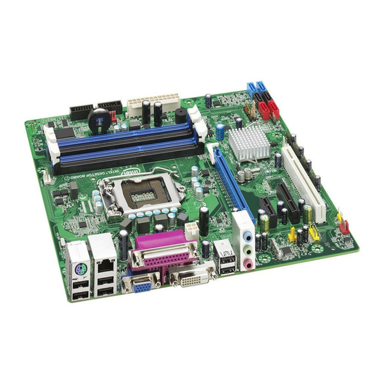
Intel Desktop Board DQ67OW Product Guide Desktop Board Components Figure 1 shows the approximate location of the major components on Intel Desktop Board DQ67OW. Figure 1. Intel Desktop Board DQ67OW Components... - Page 13 Desktop Board Features Table 2. Intel Desktop Board DQ67OW Components Label Description Conventional PCI bus add-in card connector Front panel audio header PCI Express 2.0 x4 add-in card connector Internal mono speaker header PCI Express 2.0 x1 add-in card connector PCI Express 2.0 x16 add-in card connector...
-
Page 14: Processor
Desktop Board may result in damage to the board, or the system may not function properly. Intel Desktop Board DQ67OW supports the Intel Core i7, Intel Core i5, Intel Core i3, and Intel Pentium processors in the LGA1155 package. Processors are not included with the Desktop Board and must be purchased separately. -
Page 15: Intel Q67 Express Chipset
Intel Q67 Express Chipset The Intel Q67 Express Chipset, consisting of the Intel Q67 Platform Controller Hub (PCH), provides interfaces to the processor and the USB, SATA, LPC, audio, network, display, Conventional PCI, and PCI Express interfaces. The PCH is a centralized controller for the board’s I/O paths. -
Page 16: Graphics Subsystem
DVI 1.0 specification. PCI Express* x16 Graphics The Intel Core i7, Intel Core i5, Intel Core i3, and Intel Pentium processors in an LGA1155 socket support discrete add-in graphics cards via the PCI Express 2.0 x16 add-in card connector. The board supports the following PCI Express speeds: •... -
Page 17: Lan Subsystem
The back panel audio connectors are configurable through the audio device drivers. Audio software and drivers are available from http://downloadcenter.intel.com/. LAN Subsystem The LAN subsystem includes: • Intel 82579LM Gigabit (10/100/1000 Mb/s) Ethernet LAN controller with support for: ⎯ Intel AMT 7.0 ⎯ ASF 2.0 •... -
Page 18: Usb Support
Intel Desktop Board DQ67OW Product Guide Table 3. LAN Status LEDs States LED Color LED State Indicates A (Link/Activity) Green LAN link is not established LAN link is established Blinking LAN activity is occurring B (Link Speed) 10 Mb/s data rate... -
Page 19: Intel Rapid Recover Technology
Rapid Recover Technology (Intel RRT). Intel RRT is a feature of Intel RST. Intel RRT uses RAID 1 (mirroring) functionality to copy data from a designated master drive to a designated recovery drive. The master drive data can be copied to the recovery drive either continuously or on request. -
Page 20: Sata Auto Configuration
Intel Desktop Board DQ67OW Product Guide SATA Auto Configuration If you install a SATA device (such as a hard disk drive) in your computer, the auto- configuration utility in the BIOS automatically detects and configures the device for your computer. You do not need to run the BIOS Setup program after installing a SATA device. -
Page 21: Hard Disk Drive Passwords
Desktop Board Features Hard Disk Drive Passwords NOTE On this board, the Hard Disk Drive Password Security feature is only supported on SATA port 0. Since the passwords are stored on the hard disk drive, if the drive is relocated to another SATA port or computer that does not support the Hard Disk Drive Password Security feature, the drive will not be accessible. - Page 22 Intel Desktop Board DQ67OW Product Guide During every POST, if a User hard disk drive password is set, POST execution will pause with the following prompt to force the user to enter the Master Key or User hard disk drive password:...
-
Page 23: Platform Management And Protection
® Intel vPro™ Technology Intel vPro Technology is a set of processor and platform capabilities designed to enable greater proactive security, enhanced maintenance, and improved remote management both inside and outside the corporate firewall. These include: •... - Page 24 PC Alarm Clock For more information about Intel AMT, go to http://www.intel.com/technology/platform-technology/intel-amt/index.htm. Intel AMT Software and Drivers Intel AMT software and drivers are available from Intel’s World Wide Web site. The package usually consists of the following components: ® ®...
-
Page 25: Location Of The Intel Mebx Reset Header
Desktop Board Features ® Intel MEBX Reset Header This header (see Figure 3) allows you to reset the Intel AMT configuration to the factory defaults. Momentarily shorting pins 1 and 2 with a jumper (not supplied) will accomplish the following: •... -
Page 26: Intel Virtualization Technology
Inside the firewall, this feature adapts Client Initiated Local Access (CILA); outside the firewall it uses Client Initiated Remote Access (CIRA). Many of the features of Intel AMT are available with Intel Fast Call for Help. These include Serial-over-LAN, IDE Redirection, KVM Remote Control, and PC Alarm Clock. -
Page 27: Trusted Platform Module (Tpm)
Fan Speed Control and Hardware Monitoring The features of the hardware monitoring and fan speed control include: • Thermal sensors in the processor and the Intel PCH, as well as near the processor voltage regulators and system memory • Monitoring of system voltages to detect levels above or below acceptable values •... -
Page 28: Software Support
Intel Desktop Board DQ67OW Product Guide Software Support ACPI ACPI gives the operating system direct control over the power management and Plug and Play functions of a computer. The use of ACPI with the Desktop Board requires an operating system that provides full ACPI support. - Page 29 Desktop Board Features Instantly Available PC Technology CAUTION For Instantly Available PC technology, the 5 V standby line for the power supply must be capable of delivering adequate +5 V standby current. Failure to provide adequate standby current when using this feature can damage the power supply and/or effect ACPI S3 sleep state functionality.
-
Page 30: Location Of The Standby Power Indicator
Intel Desktop Board DQ67OW Product Guide Figure 4. Location of the Standby Power Indicator For more information on standby current requirements for the Desktop Board, refer to the Technical Product Specification at http://www.intel.com/support/motherboards/desktop/. Wake from USB NOTE Wake from USB requires the use of a USB peripheral that supports Wake from USB and an operating system that supports Wake from USB. -
Page 31: Onboard Speaker
Desktop Board Features Onboard Speaker A speaker is mounted on the Desktop Board. The speaker provides audible error code (beep code) information during the Power-On Self-Test (POST). Refer to Appendix A for a description of the beep codes that may be generated during the POST. Real-Time Clock Subsystem A coin-cell battery (CR2032) powers the real-time clock and CMOS memory. - Page 32 Intel Desktop Board DQ67OW Product Guide...
-
Page 33: Installing And Replacing Desktop Board Components
2 Installing and Replacing Desktop Board Components This chapter tells you how to: • Install the I/O shield • Install and remove the Desktop Board • Install and remove a processor • Install and remove memory • Install and remove a PCI Express x16 card •... -
Page 34: Installation Precautions
Intel Desktop Board DQ67OW Product Guide Installation Precautions When you install and test the Intel Desktop Board, observe all warnings and cautions in the installation instructions. To avoid injury, be careful of: • Sharp pins on connectors • Sharp pins on printed circuit assemblies •... -
Page 35: Installing The I/O Shield
Installing and Replacing Desktop Board Components Installing the I/O Shield The Desktop Board comes with an I/O shield. When installed in the chassis, the shield blocks radio frequency transmissions, protects internal components from dust and foreign objects, and promotes correct airflow within the chassis. Install the I/O shield before installing the Desktop Board in the chassis. -
Page 36: Installing And Removing The Desktop Board
Refer to your chassis manual for instructions on installing and removing the Desktop Board. Figure 6 shows the location of the mounting screw holes for Intel Desktop Board DQ67OW. Figure 6. Intel Desktop Board DQ67OW Mounting Screw Hole Locations... -
Page 37: Installing And Removing A Processor
Installing and Replacing Desktop Board Components Installing and Removing a Processor Instructions on how to install the processor on the Desktop Board are given below. Installing a Processor CAUTION Before installing or removing a processor, make sure the AC power has been removed by unplugging the power cord from the computer;... -
Page 38: Lift The Load Plate
Intel Desktop Board DQ67OW Product Guide 3. Rotate the socket lever to lift the load plate away from the socket (Figure 8, A). Make sure that the load plate is in the fully open position (Figure 8, B) while being careful not to damage adjacent components. -
Page 39: Remove The Processor From The Protective Cover
Installing and Replacing Desktop Board Components 4. Remove the processor from its protective cover. Hold the processor only at the edges, being careful not to touch the bottom of the processor (see Figure 9). NOTE Do not discard the processor cover. Always replace the processor cover if you remove the processor from the socket. -
Page 40: Secure The Load Plate In Place
Intel Desktop Board DQ67OW Product Guide 6. Carefully lower the socket lever (Figure 11, A) while making sure that the front edge of the load plate slides under the shoulder screw cap as the lever is lowered. Latch the socket lever under the load plate tab (Figure 11, C, D). The socket cover (Figure 11, B) will pop off as shown. -
Page 41: Installing A Processor Fan Heat Sink
Installing and Replacing Desktop Board Components Installing a Processor Fan Heat Sink Intel Desktop Board DQ67OW has mounting holes for a processor fan heat sink. For instructions on how to attach the processor fan heat sink to the Desktop Board, refer to the boxed processor manual or boxed thermal solution manual. -
Page 42: Installing And Removing System Memory
Intel Desktop Board DQ67OW Product Guide Installing and Removing System Memory Guidelines for Dual Channel Memory Configuration Desktop board DQ67OW has four 240-pin DDR3 DIMM sockets arranged in two channels (A and B). Two or Four DIMMs Install a matched pair of DIMMs equal in speed and size (see Figure 13) in the blue socket of channel A (DIMM 1) and channel B (DIMM 2). -
Page 43: Three Dimms
Installing and Replacing Desktop Board Components Three DIMMs If you want to use three DIMMs in a dual-channel configuration, install a matched pair of DIMMs equal in speed and size in DIMM 1 and DIMM 3 of channel A. Then install another DIMM equal to the speed and total size of the DIMMs installed in channel A in either DIMM 2 or DIMM 4 of channel B (Figure 15). -
Page 44: Installing Dimms
Intel Desktop Board DQ67OW Product Guide Installing DIMMs To make sure you have the correct DIMM, place it on the illustration of the DDR3 DIMM in Figure 16. All the notches should match with the DDR3 DIMM. Figure 16. Use DDR3 DIMMs... -
Page 45: Installing A Dimm
Installing and Replacing Desktop Board Components To install a DIMM, follow these steps: 1. Observe the precautions in "Before You Begin" on page 33. 2. Turn off all peripheral devices connected to the computer. Turn off the computer and disconnect the AC power cord. 3. -
Page 46: Removing Dimms
Intel Desktop Board DQ67OW Product Guide Removing DIMMs To remove a DIMM, follow these steps: 1. Observe the precautions in "Before You Begin" on page 33. 2. Turn off all peripheral devices connected to the computer. Turn off the computer. -
Page 47: Installing A Pci Express X16 Graphics Card
Installing and Replacing Desktop Board Components Follow these instructions to install a PCI Express x16 graphics card: 1. Observe the precautions in "Before You Begin" on page 33. 2. Place the card in the PCI Express x16 connector (Figure 18, A) and press down on the card until it is completely seated in the connector and the card retention notch on the card snaps into place around the retention mechanism pin on the connector. -
Page 48: Removing A Pci Express X16 Graphics Card
Intel Desktop Board DQ67OW Product Guide Removing a PCI Express x16 Graphics Card Follow these instructions to remove a PCI Express x16 graphics card from a connector: 1. Observe the precautions in "Before You Begin" on page 33. 2. Disconnect the monitor cable from the graphics card back panel connector. -
Page 49: Connecting Serial Ata (Sata) Cables
Installing and Replacing Desktop Board Components Connecting Serial ATA (SATA) Cables SATA cables support the Serial ATA protocol. Each cable can be used to connect one internal SATA drive to the Desktop Board. For correct cable function: 1. Observe the precautions in “Before You Begin” on page 33. 2. -
Page 50: Connecting Diskette Drive Cables
For correct installation of the diskette drive cable: 1. Observe the precautions in "Before You Begin" on page 33. 2. Attach the cable end labeled P1 to the diskette drive connector on the Intel Desktop Board (Figure 21, A). 3. Attach the cable end labeled P2 to the connector on the diskette drive (Figure 21, B). -
Page 51: Connecting To The Internal Headers
Connecting to the Internal Headers Before connecting cables to any of the internal headers, observe the precautions in “Before You Begin” on page 33. Figure 22 shows the location of the internal headers and connectors on Intel Desktop Board DQ67OW. Figure 22. Internal Headers... -
Page 52: Front Panel Audio Header
Intel Desktop Board DQ67OW Product Guide Front Panel Audio Header The front panel audio header shown in Figure 22, A supports both Intel High Definition Audio and AC ’97 Audio. Table 5 shows the pin assignments and signal names for HD Audio and Table 6 shows the pin assignments and signal names for AC ’97 Audio. -
Page 53: Serial Header
Installing and Replacing Desktop Board Components Serial Header Figure 22, C shows the location of the serial header. Table 8 shows the pin assignments and signal names for the serial header. Table 8. Serial Port Header Signal Name Signal Name DCD (Data Carrier Detect) RXD# (Receive Data) TXD# (Transmit Data) -
Page 54: Front Panel Header
Intel FCFH Header Figure 22, G shows the location of the Intel FCFH header. Table 12 shows the pin assignments and signal names for the Intel FCFH header. Table 12. Intel FCFH Header Signal Names... -
Page 55: Front Panel Usb 2.0 Headers
Installing and Replacing Desktop Board Components Front Panel USB 2.0 Headers Figure 22, H shows the location of the front panel USB 2.0 headers and Table 13 shows the pin assignments and signal names. Table 13. Front Panel USB 2.0 Headers Signal Names Signal Name Signal Name Power (+5 V) -
Page 56: Connecting To The Audio System
Intel Desktop Board DQ67OW Product Guide Connecting to the Audio System ® After installing the Realtek audio driver from the Intel Express Installer DVD-ROM, the multi-channel audio feature can be enabled. Figure 23 shows the back panel audio connectors. The default connector assignments are shown in the table. -
Page 57: Connecting Chassis Fan And Power Supply Cables
Installing and Replacing Desktop Board Components Connecting Chassis Fan and Power Supply Cables Connecting Chassis Fan Cables Connect chassis fan cables to the chassis fan headers on the Desktop Board. Figure 24 shows the location of the chassis fan headers. Figure 24. -
Page 58: Connecting Power Supply Cables
Intel Desktop Board DQ67OW Product Guide Connecting Power Supply Cables CAUTION Failure to use an appropriate power supply and/or not connecting the 12 V power connector (Figure 25, A) to the Desktop Board may result in damage to the board or the system may not function properly. -
Page 59: Setting The Bios Configuration Jumper
Installing and Replacing Desktop Board Components Setting the BIOS Configuration Jumper NOTE Always turn off the power to the computer before moving the jumper. Moving the jumper with the power on may result in unreliable computer operation. Figure 26 shows the location of the Desktop Board’s BIOS configuration jumper block. Figure 26. -
Page 60: Clearing Passwords In The Bios Setup Program
Intel Desktop Board DQ67OW Product Guide The three-pin BIOS jumper block enables board configuration to be done in the BIOS Setup program. Table 15 shows the jumper settings for the BIOS Setup program modes. Table 15. Jumper Settings for the BIOS Setup Program Modes... -
Page 61: Replacing The Battery
Installing and Replacing Desktop Board Components 6. Replace the cover, plug in the computer, turn on the computer, and allow it to boot. 7. The computer starts the Setup program. Setup displays the Maintenance menu. 8. Use the arrow keys to select Clear Passwords. Press <Enter> and Setup displays a pop-up screen requesting that you confirm clearing the password. - Page 62 Intel Desktop Board DQ67OW Product Guide FORHOLDSREGEL Eksplosionsfare, hvis batteriet erstattes med et batteri af en forkert type. Batterier bør om muligt genbruges. Bortskaffelse af brugte batterier bør foregå i overensstemmelse med gældende miljølovgivning. OBS! Det kan oppstå eksplosjonsfare hvis batteriet skiftes ut med feil type. Brukte batterier bør kastes i henhold til gjeldende miljølovgivning.
- Page 63 Installing and Replacing Desktop Board Components AŚCIAROŽZNAŚĆ Існуе рызыка выбуху, калі заменены акумулятар неправільнага тыпу. Акумулятары павінны, па магчымасці, перепрацоўвацца. Пазбаўляцца ад старых акумулятараў патрэбна згодна з мясцовым заканадаўствам па экалогіі. UPOZORNÌNÍ V případě výměny baterie za nesprávný druh může dojít k výbuchu. Je-li to možné, baterie by měly být recyklovány.
- Page 64 Intel Desktop Board DQ67OW Product Guide ВНИМАНИЕ При использовании батареи несоответствующего типа существует риск ее взрыва. Батареи должны быть утилизированы по возможности. Утилизация батарей должна проводится по правилам, соответствующим местным требованиям. UPOZORNENIE Ak batériu vymeníte za nesprávny typ, hrozí nebezpečenstvo jej výbuchu. Batérie by sa mali podľa možnosti vždy recyklovať.
- Page 65 Installing and Replacing Desktop Board Components...
-
Page 66: Removing The Battery
Intel Desktop Board DQ67OW Product Guide To replace the battery, follow these steps: 1. Observe the precautions in "Before You Begin" (see page 33). 2. Turn off all peripheral devices connected to the computer and turn off the computer. Disconnect the computer’s power cord from the AC power source (wall outlet or power adapter). -
Page 67: Updating The Bios
Power-On Self-Test (POST) memory test begins and before the operating system boot begins. This chapter tells you how to update the BIOS by either using the Intel Express BIOS Update utility or the Intel Flash Memory Update Utility, and how to recover the BIOS ®... -
Page 68: Updating The Bios Using The F7 Function Key
Intel Desktop Board DQ67OW Product Guide Updating the BIOS Using the F7 Function Key To use this BIOS update method: 1. Download and save the Recovery BIOS (.BIO) file to a temporary directory. 2. Copy the .BIO file to a USB thumb drive. The USB thumb drive does not need to be bootable, only formatted. -
Page 69: Updating The Bios With The Iso Image Bios Update File Or The Intel Flash Memory Update Utility
Intel Desktop Board DQ67OW page on the Intel World Wide Web site Download Center at http://downloadcenter.intel.com. On the DQ67OW page, click on the “BIOS Update” link and then select the the Iflash BIOS Update file. Updating the BIOS with the Intel Flash Memory Update... -
Page 70: Updating The Bios With The Iso Image Bios Update File
Enter key. The system will boot from the hard drive if no key is pressed within 15 seconds. 5. At the "Welcome to the Intel Desktop Board BIOS Upgrade CD-ROM" page, press any key to confirm the BIOS upgrade operation. -
Page 71: Recovering The Bios
CD-R with the .BIO file in the root directory will be required. You can obtain the Recovery BIOS Update file through your computer supplier or by navigating to the Intel Desktop Board DQ67OW page on the Intel World Wide Web site Download Center at http://downloadcenter.intel.com. - Page 72 Intel Desktop Board DQ67OW Product Guide...
-
Page 73: A Error Messages And Indicators
A Error Messages and Indicators Intel Desktop Board DQ67OW reports POST errors in two ways: • By sounding a beep code and blinking the front panel power LED • By displaying an error message on the monitor BIOS Error Codes Whenever a recoverable error occurs during POST, the BIOS causes the board’s... -
Page 74: Bios Error Messages
Intel Desktop Board DQ67OW Product Guide Table 17. Front-panel Power LED Blink Codes Type Pattern Note F2 Setup/F10 Boot None Menu Prompt BIOS update in Off when the update begins, then on for progress 0.5 seconds, then off for 0.5 seconds. The pattern repeats until the BIOS update is complete. -
Page 75: B Regulatory Compliance
Product Ecology statements • Electromagnetic Compatibility (EMC) regulations • Product certifications Safety Standards Intel Desktop Board DQ67OW complies with the safety standards stated in Table 19 when correctly installed in a compatible host system. Table 19. Safety Standards Regulation Title CSA/UL 60950-1 Information Technology Equipment –... -
Page 76: European Union Declaration Of Conformity Statement
Intel Desktop Board DQ67OW Product Guide European Union Declaration of Conformity Statement We, Intel Corporation, declare under our sole responsibility that the product Intel ® Desktop Board DQ67OW is in conformity with all applicable essential requirements necessary for CE marking, following the provisions of the European Council Directives 2004/108/EC (EMC Directive), 2006/95/EC (Low Voltage Directive), and 2002/95/EC (ROHS Directive). -
Page 77: Product Ecology Statements
The following information is provided to address worldwide product ecology concerns and regulations. Recycling Considerations As part of its commitment to environmental responsibility, Intel has implemented the ® Intel Product Recycling Program to allow retail consumers of Intel’s branded products to return used products to selected locations for proper recycling. - Page 78 Français Dans le cadre de son engagement pour la protection de l'environnement, Intel a mis en œuvre le programme Intel Product Recycling Program (Programme de recyclage des produits Intel) pour permettre aux consommateurs de produits Intel de recycler les produits usés en les retournant à...
- Page 79 Regulatory Compliance Portuguese Como parte deste compromisso com o respeito ao ambiente, a Intel implementou o Programa de Reciclagem de Produtos para que os consumidores finais possam enviar produtos Intel usados para locais selecionados, onde esses produtos são reciclados de maneira adequada.
-
Page 80: China Rohs
The China Ministry of Information Industry (MII) stipulates that a material Self Declaration Table (SDT) must be included in a product’s user documentation. The SDT for Intel Desktop Board DQ67OW is shown in Figure 28. Figure 28. Intel Desktop Board DQ67OW China RoHS Material... -
Page 81: Emc Regulations
Regulatory Compliance EMC Regulations Intel Desktop Board DQ67OW complies with the EMC regulations stated in Table 20 when correctly installed in a compatible host system. Table 20. EMC Regulations Regulation Title FCC 47 CFR Part 15, Title 47 of the Code of Federal Regulations, Part 15, Subpart B, Subpart B Radio Frequency Devices. -
Page 82: Canadian Department Of Communications Compliance Statement
• Consult the dealer or an experienced radio/TV technician for help. Any changes or modifications to the equipment not expressly approved by Intel Corporation could void the user’s authority to operate the equipment. Tested to comply with FCC standards for home or office use. -
Page 83: Korea Class B Statement
Regulatory Compliance Korea Class B Statement Korea Class B Statement translation: This equipment is for home use, and has acquired electromagnetic conformity registration, so it can be used not only in residential areas, but also other areas. Ensure Electromagnetic Compatibility (EMC) Compliance Before computer integration, make sure that the power supply and other modules or peripherals, as applicable, have passed Class B EMC testing and are marked... -
Page 84: Product Certifications
Intel Desktop Board DQ67OW Product Guide Product Certifications Board-Level Certifications Intel Desktop Board DQ67OW has the regulatory compliance marks shown in Table 21. Table 21. Regulatory Compliance Marks Description Mark UL joint US/Canada Recognized Component mark. Includes adjacent UL file number for Intel Desktop Boards: E210882. -
Page 85: Chassis- And Component-Level Certifications
Compliance The US Department of Energy and the US Environmental Protection Agency have continually revised the ENERGY STAR requirements. Intel has worked directly with these two governmental agencies in the definition of the new requirements. This Desktop Board meets the ENERGY STAR Program for Computers: Version 5.0 Category A requirements. - Page 86 Intel Desktop Board DQ67OW Product Guide...
Need help?
Do you have a question about the DQ67OW and is the answer not in the manual?
Questions and answers