Table of Contents
Advertisement
Advertisement
Table of Contents

Related Manuals for Asus P8P67 LE


Summary of Contents for Asus P8P67 LE
- Page 1 P8P67 LE...
- Page 2 Product warranty or service will not be extended if: (1) the product is repaired, modified or altered, unless such repair, modification of alteration is authorized in writing by ASUS; or (2) the serial number of the product is defaced or missing.
-
Page 3: Table Of Contents
Contents Notices ......................vi Safety information ..................vii About this guide ..................vii P8P67 LE specifications summary ............ix Chapter 1: Product introduction Welcome! ..................1-1 Package contents ................. 1-1 Special features ................1-1 1.3.1 Product highlights ............1-1 1.3.2 Innovative ASUS features .......... - Page 4 Managing and updating your BIOS ..........2-1 2.1.1 ASUS Update utility ............2-1 2.1.2 ASUS EZ Flash 2 ............2-2 2.1.3 ASUS CrashFree BIOS 3 utility ........2-3 2.1.4 ASUS BIOS Updater ............2-4 BIOS setup program ..............2-7 Main menu .................. 2-11 2.3.1 System Language ............2-11...
- Page 5 Setup Mode ..............2-27 2.7.5 Boot Option Priorities ............ 2-28 2.7.6 Boot Override ..............2-28 Tools menu ................. 2-29 2.8.1 ASUS EZ Flash Utility ........... 2-29 2.8.2 ASUS SPD Information ..........2-29 2.8.3 ASUS O.C. Profile ............2-29 Exit menu ..................2-30...
-
Page 6: Notices
Complying with the REACH (Registration, Evaluation, Authorisation, and Restriction of Chemicals) regulatory framework, we published the chemical substances in our products at ASUS REACH website at http://csr.asus.com/english/REACH.htm. DO NOT throw the motherboard in municipal waste. This product has been designed to enable proper reuse of parts and recycling. -
Page 7: Safety Information
Safety information Electrical safety • To prevent electric shock hazard, disconnect the power cable from the electric outlet before relocating the system. • When adding or removing devices to or from the system, ensure that the power cables for the devices are unplugged before the signal cables are connected. If possible, disconnect all power cables from the existing system before you add a device. -
Page 8: Conventions Used In This Guide
Refer to the following sources for additional information and for product and software updates. ASUS websites The ASUS website provides updated information on ASUS hardware and software products. Refer to the ASUS contact information. Optional documentation Your product package may include optional documentation, such as warranty flyers, that may have been added by your dealer. -
Page 9: P8P67 Le Specifications Summary
Extreme Memory Profile (XMP) ® The maximum 32GB memory capacity can be supported with 8GB or above DIMMs. ASUS will update the memory QVL once the DIMMs are available in the market. ** Hyper DIMM support is subject to the physical characteristics of individual CPUs. - Page 10 ASUS Anti-Surge Protection Low EMI ASUS Hybrid Switches - MemOK! - TPU ASUS Quiet Thermal Solutions - ASUS Fanless Design: Stylish Heatsink Solution & MOS Heatsink - ASUS Fan Xpert ASUS EZ DIY - EFI BIOS - ASUS AI Suite II...
- Page 11 SFS (Stepless Frequency Selection): - BCLK/PEG frequency tuning from 80MHz up to 300MHz at 1MHz increment Overclocking protection: - ASUS C.P.R. (CPU Parameter Recall) Other features 100% All High-quality Conductive Polymer Capacitors Rear panel ports 1 x PS/2 Mouse port (green)
- Page 12 P8P67 LE specifications summary Support DVD Drivers ASUS utilities ASUS Update Anti-virus software (OEM version) Form factor ATX form factor: 12 in x 8.8 in (30.5 cm x 22.4 cm) * Specifications are subject to change without notice.
-
Page 13: Chapter 1: Product Introduction
® The motherboard delivers a host of new features and latest technologies, making it another standout in the long line of ASUS quality motherboards! Before you start installing the motherboard, and hardware devices on it, check the items in your package with the list below. - Page 14 • The maximum 32GB memory capacity can be supported with 8GB or above DIMMs. ASUS will update the memory QVL once the DIMMs are available in the market. • Hyper DIMM support is subject to the physical characteristics of individual CPUs.
-
Page 15: Innovative Asus Features
Innovative ASUS features ASUS EFI BIOS (EZ Mode) ASUS brand new EFI BIOS offers a user-friendly interface that goes beyond traditional keyboard BIOS input to enable more flexible and convenient mouse controls. You can easily navigate the new EFI BIOS with the same smoothness as their operating system. -
Page 16: Asus Turbov
Get your system up and running in no time. ASUS TurboV Feel the adrenaline rush of real-time OC-now a reality with the ASUS TurboV. This easy OC tool allows you to overclock without exiting or rebooting the OS; and its user-friendly interface makes overclock with just a few clicks away. -
Page 17: Asus Mylogo2
BIOS file using the bundled support DVD or USB flash disk that contains the latest BIOS file. ASUS EZ Flash 2 ASUS EZ Flash 2 is a utility that allows you to update the BIOS without using an OS-based utility. C.P.R. (CPU Parameter Recall) The BIOS C.P.R. -
Page 18: Before You Proceed
• Before you install or remove any component, ensure that the ATX power supply is switched off or the power cord is detached from the power supply. Failure to do so may cause severe damage to the motherboard, peripherals, or components. ASUS P8P67 LE... -
Page 19: Motherboard Overview
Place six screws into the holes indicated by circles to secure the motherboard to the chassis. Do not overtighten the screws! Doing so can damage the motherboard. Place this side towards the rear of the chassis P8P67 LE Chapter 1: Product introduction... -
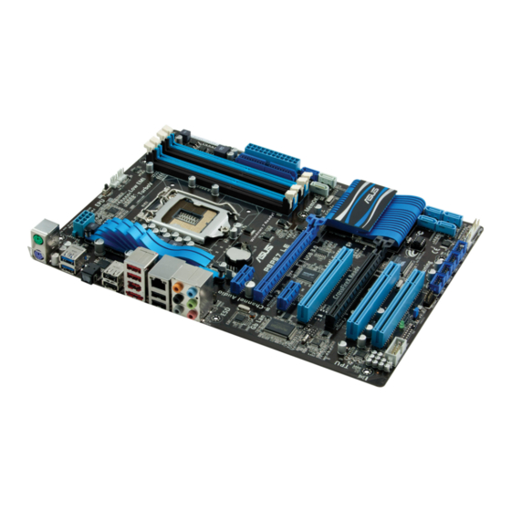
Page 20: Motherboard Layout
Lithium Cell AUDIO CMOS Power AAFP PCIEX1_1 P8P67 LE Marvell SATA6G 8111E PCIEX16_1 asmedia PCIEX1_2 ASM1085 Super Intel ® PCI1 PCIEX16_2 PCI2 VT6308P 32Mb BIOS PCI3 CHA_FAN2 SPDIF_OUT IE1394_1 USB78 USB910 USB1112 USB1314 PANEL CLRTC SB_PWR COM1 ASUS P8P67 LE... -
Page 21: Layout Contents
1.5.4 Layout contents Connectors/Jumpers/Slots/LED Page Connectors/Jumpers/Slots/LED Page Front panel audio connector (10-1 pin AAFP) 1-28 Marvell Serial ATA 6.0Gb/s connector (7-pin 1-34 ® SATA6G_E1 [navy blue]) ATX power connectors (24-pin EATXPWR, 1-30 Intel P67 Serial ATA 6.0Gb/s connectors 1-32 ® 8-pin EATX12V) (7-pin SATA6G_1/2 [gray]) CPU, chassis, and power fan connectors... -
Page 22: Central Processing Unit (Cpu)
Contact your retailer immediately if the PnP cap is missing, or if you see any damage to the PnP cap/socket contacts/motherboard components. ASUS will shoulder the cost of repair only if the damage is shipment/transit-related. • Keep the cap after installing the motherboard. ASUS will process Return Merchandise Authorization (RMA) requests only if the motherboard comes with the cap on the LGA1155 socket. - Page 23 Lift the load lever in the direction of the arrow until the load plate is completely lifted. Load plate Remove the PnP cap from the CPU socket by lifting the tab only. PnP cap Position the CPU over the socket, ensuring that the gold triangle is on the bottom-left corner of the socket, and CPU notches...
- Page 24 Close the load plate (A), and then push down the load lever (B), ensuring that the front edge of the load plate slides under the retention knob (C). Insert the load lever under the retention tab. 1-12 ASUS P8P67 LE...
-
Page 25: Installing The Cpu Heatsink And Fan
1.6.2 Installing the CPU heatsink and fan The Intel LGA1155 processor requires a specially designed heatsink and fan assembly to ® ensure optimum thermal condition and performance. • When you buy a boxed Intel processor, the package includes the CPU fan and ®... -
Page 26: Uninstalling The Cpu Heatsink And Fan
Connect the CPU fan cable to the connector on the motherboard labeled CPU_FAN. CPU_FAN P8P67 LE P8P67 LE CPU fan connector Do not forget to connect the CPU fan connector! Hardware monitoring errors can occur if you fail to plug this connector. -
Page 27: System Memory
The figure illustrates the location of the DDR3 DIMM sockets: Channel Sockets Channel A DIMM_A1 and DIMM_A2 P8P67 LE Channel B DIMM_B1 and DIMM_B2 P8P67 LE 240-pin DDR3 DIMM sockets Chapter 1: Product introduction 1-15... -
Page 28: Memory Configurations
• The maximum 32GB memory capacity can be supported with 8GB or above DIMMs. ASUS will update the memory QVL once the DIMMs are available in the market. • The default memory operation frequency is dependent on its Serial Presence Detect (SPD), which is the standard way of accessing information from a memory module. - Page 29 P8P67 LE Motherboard Qualified Vendors Lists (QVL) DDR3-2200(O.C.) MHz capability DIMM socket support (Optional) SS/DS Chip Vendors Part No. Size Brand Chip NO. Timing Voltage G.SKILL F3-17600CL8D-4GBPS(XMP) 4GB(2 x 2GB) DS 8-8-8-24 1.65V • KINGMAX FLKE85F-B8KJAA-FEIS(XMP) 2GB • • Kingmax...
- Page 30 • Mushkin 998659(XMP) 6GB(3 x 2GB) DS - 9-9-9-24 • • • Mushkin 998659(XMP) 6GB(3 x 2GB) DS - 9-9-9-24 1.5~1.6V • • • PATRIOT PGS34G1600LLKA 4GB(2 x 2GB) DS - 7-7-7-20 1.7V • • • 1-18 ASUS P8P67 LE...
- Page 31 DDR3-1333 MHz capability DIMM socket Chip support (Optional) Vendors Part No. Size Chip NO. Timing Voltage Brand AD30908C8D-151C A-Data AD31333001GOU A-Data • • • E0906 A-Data AD31333G001GOU 3GB(3 x 1GB) SS 8-8-8-24 1.65-1.85V • • AD30908C8D-151C A-Data AD31333002GOU A-Data • •...
- Page 32 • • • TAKEMS TMS2GB364D081-107EY 7-7-7-20 1.5V • • TAKEMS TMS2GB364D081-138EY 8-8-8-24 1.5V • • • TAKEMS TMS2GB364D082-138EW 8-8-8-24 1.5V • • UMAX E41302GP0-73BDB UMAX U2S24D30TP-13 • • • WINTEC 3WVS31333-2G-CNR AMPO AM3420803-13H • • • 1-20 ASUS P8P67 LE...
- Page 33 • C*: Supports two pairs of modules inserted into both the blue slots and the black slots as two pairs of dual-channel memory configuration. Visit the ASUS website at www.asus.com for the latest QVL. Chapter 1: Product introduction 1-21...
-
Page 34: Installing A Dimm
DIMM. Support the DIMM lightly with your fingers when pressing the retaining clips. The DIMM might get damaged when it flips out with extra force. DIMM notch Remove the DIMM from the socket. 1-22 ASUS P8P67 LE... -
Page 35: Expansion Slots
Expansion slots In the future, you may need to install expansion cards. The following sub-sections describe the slots and the expansion cards that they support. Unplug the power cord before adding or removing expansion cards. Failure to do so may cause you physical injury and damage motherboard components. - Page 36 • The PCIe x1 slots share the bandwidth with the PCIe x16_2 slot. Thus, all PCIe x1 slots will be disabled when you install two CrossFireX™ graphics cards on both the PCIe x16 slots to set up a CrossFireX™ configuration. 1-24 ASUS P8P67 LE...
-
Page 37: Jumpers
Normal Clear RTC (Default) P8P67 LE Clear RTC RAM To erase the RTC RAM: 1. Turn OFF the computer and unplug the power cord. 2. Move the jumper cap from pins 1-2 (default) to pins 2-3. Keep the cap on pins 2-3 for about 5-10 seconds, then move the cap back to pins 1-2. -
Page 38: Connectors
8-channel configurations, the function of this port becomes Front Speaker Out. Microphone port (pink). This port connects to a microphone. Side Speaker Out port (gray). This port connects to the side speakers in the 8-channel audio configuration. 1-26 ASUS P8P67 LE... - Page 39 Refer to the audio configuration table below for the function of the audio ports in the 2, 4, 6, or 8-channel configuration. Audio 2, 4, 6, or 8-channel configuration Headset Port 4-channel 6-channel 8-channel 2-channel Light Blue Line In Line In Line In Line In Lime...
-
Page 40: Internal Connectors
Legacy AC’97 pin definition compliant definition P8P67 LE Front panel audio connector • We recommend that you connect a high-definition front panel audio module to this connector to avail of the motherboard’s high-definition audio capability. • If you want to connect a high-definition front panel audio module to this connector, set the Front Panel Type item in the BIOS setup to [HD]. - Page 41 P8P67 LE PIN1 NOTE:Orient the red markings on the IDE ribbon cable to PIN 1. P8P67 LE IDE connector If any device jumper is set as “Cable-Select,” ensure that all other device jumpers have the same setting. Chapter 1: Product introduction...
- Page 42 • If you are uncertain about the minimum power supply requirement for your system, refer to the Recommended Power Supply Wattage Calculator at http://support.asus. com/PowerSupplyCalculator/PSCalculator.aspx?SLanguage=en-us for details. Serial port connector (10-1 pin COM1) This connector is for a serial (COM) port.
- Page 43 • The CPU_FAN connector supports a CPU fan of maximum 2A (24 W) fan power. • Only the CPU_FAN, CHA_FAN1 and CHA_FAN2 connectors support the ASUS Fan Xpert feature. • If you install two VGA cards, we recommend that you plug the rear chassis fan cable to the motherboard connector labeled CHA_FAN1 or CAH_FAN 2 for better thermal environment.
- Page 44 RSATA_TXN1 RSATA_RXP2 RSATA_TXP1 RSATA_RXN2 P8P67 LE Intel SATA 6.0 Gb/s connectors ® • These connectors are set to [AHCI Mode] by default. If you intend to create a Serial ATA RAID set using these connectors, set the SATA Mode item in the BIOS to [RAID Mode].
- Page 45 RSATA_TXN4 RSATA_RXP2 RSATA_TXP4 RSATA_RXN2 P8P67 LE Intel SATA 3.0 Gb/s connectors ® • These connectors are set to [AHCI Mode] by default. If you intend to create a Serial ATA RAID set using these connectors, set the SATA Mode item in the BIOS to [RAID Mode].
- Page 46 SATA6G_E1 RSATA_TXP1 RSATA_TXN1 P8P67 LE RSATA_RXP1 RSATA_RXN1 P8P67 LE Marvell SATA 6.0 Gb/s connector ® • The SATA6G_E1 (navy blue) connector is for data drives only. ATAPI device is not supported. • You must install Windows XP Service Pack 3 or later versions before using Serial ATA ®...
- Page 47 IDE_LED PWRSW RESET * Requires an ATX power supply P8P67 LE System panel connector • System power LED (2-pin PLED) This 2-pin connector is for the system power LED. Connect the chassis power LED cable to this connector. The system power LED lights up when you turn on the system power, and blinks when the system is in sleep mode.
-
Page 48: Onboard Switches
P8P67 LE PIN 1 PIN 1 PIN 1 PIN 1 P8P67 LE USB2.0 connectors Never connect a 1394 cable to the USB connectors. Doing so will damage the motherboard! The USB module cable is purchased separately. 1.11 Onboard switches Onboard switches allow you to fine-tune performance when working on a bare or open-case system. - Page 49 If the installed DIMMs still fail to boot after the whole tuning process, the DRAM_LED lights continuously. Replace the DIMMs with ones recommended in the Memory QVL (Qualified Vendors Lists) in this user manual or on the ASUS website at www.asus.com.
-
Page 50: Onboard Leds
P8P67 LE Standby Power Powered Off P8P67 LE Onboard LED DRAM LED DRAM LED checks the DRAM in sequence during motherboard booting process. If an error is found , the LED next to the error device will continue lighting until the problem is solved. -
Page 51: Software Support
The contents of the Support DVD are subject to change at any time without notice. Visit the ASUS website at www.asus.com for updates. To run the Support DVD Place the Support DVD to the optical drive. - Page 52 1-40 ASUS P8P67 LE...
-
Page 53: Chapter 2: Bios Information
BIOS in the future. Copy the original motherboard BIOS using the ASUS Update utility. 2.1.1 ASUS Update utility The ASUS Update is a utility that allows you to manage, save, and update the motherboard BIOS in Windows environment. ®... -
Page 54: Asus Ez Flash 2
Follow the onscreen instructions to complete the updating process. 2.1.2 ASUS EZ Flash 2 The ASUS EZ Flash 2 feature allows you to update the BIOS without using an OS-based utility. Before you start using this utility, download the latest BIOS file from the ASUS website at www.asus.com. -
Page 55: Asus Crashfree Bios 3 Utility
2.1.3 ASUS CrashFree BIOS 3 utility The ASUS CrashFree BIOS 3 is an auto recovery tool that allows you to restore the BIOS file when it fails or gets corrupted during the updating process. You can restore a corrupted BIOS file using the motherboard support DVD or a USB flash drive that contains the updated BIOS file. -
Page 56: Asus Bios Updater
2.1.4 ASUS BIOS Updater The ASUS BIOS Updater allows you to update BIOS in DOS environment. This utility also allows you to copy the current BIOS file that you can use as a backup when the BIOS fails or gets corrupted during the updating process. - Page 57 The BIOS Updater backup screen appears indicating the BIOS backup process. When BIOS backup is done, press any key to return to the DOS prompt. ASUSTek BIOS Updater for DOS V1.18 Current ROM Update ROM BOARD: P8P67 LE BOARD: Unknown VER: 0711 VER:...
-
Page 58: Updating The Bios File
Select the Load Optimized Defaults item under the Exit menu. Refer to section 2.9 Exit menu for details. • Ensure to connect all SATA hard disk drives after updating the BIOS file if you have disconnected them. ASUS P8P67 LE... -
Page 59: Bios Setup Program
• The BIOS setup screens shown in this section are for reference purposes only, and may not exactly match what you see on your screen. • Visit the ASUS website at www.asus.com to download the latest BIOS file for this motherboard. -
Page 60: Bios Menu Screen
Selects the boot device priority • The boot device options vary depending on the devices you installed to the system. • The Boot Menu(F8) button is available only when the boot device is installed to the system. ASUS P8P67 LE... -
Page 61: Advanced Mode
The Advanced Mode provides advanced options for experienced end-users to configure the BIOS settings. The figure below shows an example of the Advanced Mode. Refer to the following sections for the detailed configurations. To access the EZ Mode, click Exit, then select ASUS EZ Mode. Back button Menu items... -
Page 62: Menu Items
You cannot select an item that is not user-configurable. A configurable field is highlighted when selected. To change the value of a field, select it and press <Enter> to display a list of options. 2-10 ASUS P8P67 LE... -
Page 63: Main Menu
Main menu The Main menu screen appears when you enter the Advanced Mode of the BIOS Setup program. The Main menu provides you an overview of the basic system information, and allows you to set the system date, time, language, and security settings. EFI BIOS Utility - Advanced Mode Exit Main... -
Page 64: Administrator Password
To clear the user password, follow the same steps as in changing a user password, but press <Enter> when prompted to create/confirm the password. After you clear the password, the User Password item on top of the screen shows Not Installed. 2-12 ASUS P8P67 LE... -
Page 65: Ai Tweaker Menu
Ai Tweaker menu The Ai Tweaker menu items allow you to configure overclocking-related items. Be cautious when changing the settings of the Ai Tweaker menu items. Incorrect field values can cause the system to malfunction. The configuration options for this section vary depending on the CPU and DIMM model you installed on the motherboard. -
Page 66: Ai Overclock Tuner
Selecting a very high memory frequency may cause the system to become unstable! If this happens, revert to the default setting. 2.4.4 EPU Power Saving Mode [Disabled] Allows you to enable or disable the EPU power saving function. Configuration options: [Disabled] [Enabled] 2-14 ASUS P8P67 LE... -
Page 67: Oc Tuner
EPU Setting [AUTO] This item appears only when you set the EPU Power Saving MODE item to [Enabled] and allows you to select the EPU power saving mode. Configuration options: [AUTO] [Light Power Saving Mode] [Medium Power Saving Mode] [Max Power Saving Mode] 2.4.5 OC Tuner OC Tuner automatically overclocks the frequency and voltage of CPU and DRAM for... -
Page 68: Offset Mode Sign
• The values of the CPU Offset Voltage, DRAM Voltage, VCCIO Voltage, and PCH Voltage items are labeled in different color, indicating the risk levels of high voltage settings. • The system may need better cooling system to work stably under high voltage settings. 2-16 ASUS P8P67 LE... -
Page 69: Load-Line Calibration
2.4.12 Load-Line Calibration [Auto] Load-line is defined by Intel VRM specification and affects CPU voltage. The CPU working voltage will decrease proportionally to CPU loading. Higher load-line calibration would get higher voltage and better overclocking performance, but increase the CPU and VRM thermal. This item allows you to set this function for better system performance. -
Page 70: Advanced Menu
Enables the overheated CPU to throttle its clock speed to cool down. [Disabled] Disables the CPU thermal monitor function. Active Processor Cores [All] Allows you to choose the number of CPU cores to activate in each processor package. Configuration options: [All] [1] [2] [3] 2-18 ASUS P8P67 LE... -
Page 71: System Agent Configuration
Limit CPUID Maximum [Disabled] [Enabled] Allows legacy operating systems to boot even without support for CPUs with extended CPUID functions. [Disabled] Disables this function. Execute Disable Bit [Enabled] [Enabled] Enables the No-Execution Page Protection Technology. [Disabled] Forces the XD feature flag to always return to zero (0). Intel Virtualization Technology [Disabled] [Enabled] Allows a hardware platform to run multiple operating systems separately... -
Page 72: Pch Configuration
The USB devices can be used only for the BIOS setup program. [Auto] Allows the system to detect the presence of USB devices at startup. If detected, the USB controller legacy mode is enabled. If no USB device is detected, the legacy USB support is disabled. 2-20 ASUS P8P67 LE... -
Page 73: Onboard Devices Configuration
Legacy USB3.0 Support [Enabled] [Enabled] Enables the support for USB 3.0 devices on legacy operating systems (OS). [Disabled] Disables the function. EHCI Hand-off [Disabled] [Enabled] Enables the support for operating systems without an EHCI hand-off feature. [Disabled] Disables the function. 2.5.6 Onboard Devices Configuration HD Audio Controller [Enabled]... -
Page 74: Serial Port Configuration
Allows you to enable or disable the serial port (COM). Configuration options: [Enabled] [Disabled] Change Settings [IO=3F8h; IRQ=4] Allows you to select the Serial Port base address. Configuration options: [IO=3F8h; IRQ=4] [IO=2F8h; IRQ=3] [IO=3E8h; IRQ=4] [IO=2E8h; IRQ=3] 2-22 ASUS P8P67 LE... -
Page 75: Apm
2.5.7 Restore AC Power Loss [Power Off] [Power On] The system goes into on state after an AC power loss. [Power Off] The system goes into off state after an AC power loss. [Last State] The system goes into either off or on state, whatever the system state was before the AC power loss. -
Page 76: Monitor Menu
The onboard hardware monitor automatically detects and displays the CPU, chassis, and power fan speeds in rotations per minute (RPM). If the fan is not connected to the motherboard, the field shows N/A. Select Ignore if you do not wish to display the detected speed. 2-24 ASUS P8P67 LE... - Page 77 2.6.3 CPU Q-Fan Control [Enabled] [Disabled] Disables the CPU Q-Fan control feature. [Enabled] Enables the CPU Q-Fan control feature. CPU Fan Speed Low Limit [600 RPM] This item appears only when you enable the CPU Q-Fan Control feature and allows you to disable or set the CPU fan warning speed.
-
Page 78: Cpu Voltage, 3.3V Voltage, 5V Voltage, 12V Voltage
The onboard hardware monitor automatically detects the voltage output through the onboard voltage regulators. Select Ignore if you do not want to detect this item. 2.6.6 Anti Surge Support [Enabled] This item allows you to enable or disable the Anti Surge function. Configuration options: [Disabled] [Enabled] 2-26 ASUS P8P67 LE... -
Page 79: Boot Menu
[Enabled] Enables the full screen logo display feature. [Disabled] Disables the full screen logo display feature. Set this item to [Enabled] to use the ASUS MyLogo 2™ feature. 2.7.3 Option ROM Messages [Force BIOS] [Force BIOS] The third-party ROM messages will be forced to display during the boot sequence. -
Page 80: Boot Option Priorities
• To select the boot device during system startup, press <F8> when ASUS Logo appears. • To access Windows OS in Safe Mode, do any of the following: - Press <F5>... -
Page 81: Tools Menu
> ASUS O.C. Profile 2.8.1 ASUS EZ Flash Utility Allows you to run ASUS EZ Flash 2. Press [Enter] to launch the ASUS EZ Flash 2 screen. For more details, see section 2.1.2 ASUS EZ Flash 2. 2.8.2 ASUS SPD Information... -
Page 82: Exit Menu
This option allows you to enter the EZ Mode screen. Launch EFI Shell from filesystem device This option allows you to attempt to launch the EFI Shell application (shellx64.efi) from one of the available devices that have a filesystem. 2-30 ASUS P8P67 LE... -
Page 83: Asus Contact Information
+1-510-739-3777 +1-510-608-4555 Web site usa.asus.com Technical Support Telephone +1-812-282-2787 Support fax +1-812-284-0883 Online support support.asus.com ASUS COMPUTER GmbH (Germany and Austria) Address Harkort Str. 21-23, D-40880 Ratingen, Germany +49-2102-959911 Web site www.asus.de Online contact www.asus.de/sales Technical Support Telephone (Component) +49-1805-010923*...
Need help?
Do you have a question about the P8P67 LE and is the answer not in the manual?
Questions and answers