Table of Contents
Advertisement
Advertisement
Table of Contents

Related Manuals for Gigabyte GA-B75M-D3H


Summary of Contents for Gigabyte GA-B75M-D3H
- Page 1 GA-B75M-D3H User's Manual Rev. 1002 12ME-B75MD3H-1002R...
-
Page 3: Identifying Motherboard Revision
The trademarks mentioned in this manual are legally registered to their respective owners. Disclaimer Information in this manual is protected by copyright laws and is the property of GIGABYTE. Changes to the specifications and features in this manual may be made by GIGABYTE without prior notice. -
Page 4: Table Of Contents
Table of Contents GA-B75M-D3H Motherboard Layout ................5 GA-B75M-D3H Motherboard Block Diagram ..............6 Chapter 1 Hardware Installation ..................7 Installation Precautions ..................7 Product Specifications ..................8 Installing the CPU ..................10 Installing the Memory ..................11 Installing an Expansion Card ................. 11 Back Panel Connectors .................. -
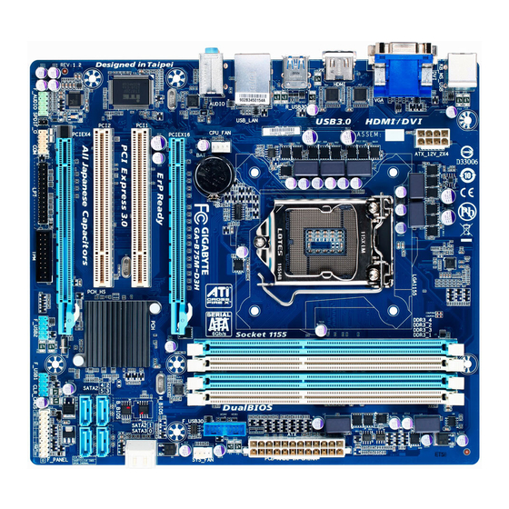
Page 5: Ga-B75M-D3H Motherboard Layout
GA-B75M-D3H Motherboard Layout KB_MS_USB ATX_12V LGA1155 HDMI R_USB30 USB_LAN CPU_FAN AUDIO GA-B75M-D3H PCIEX16 Realtek GbE LAN PCI1 M_BIOS SATA3 SATA2 PCI2 B_BIOS Intel ® SATA2 PCIEX4 CODEC CLR_CMOS F_AUDIO F_USB2 F_USB1 F_PANEL SPDIF_O Box Contents GA-B75M-D3H motherboard Motherboard driver disk... -
Page 6: Ga-B75M-D3H Motherboard Block Diagram
GA-B75M-D3H Motherboard Block Diagram CPU CLK+/- (100 MHz) 1 PCI Express x16 PCIe CLK LGA1155 CPU DDR3 1600 /1333/1066 MHz (Note 1) (100 MHz) Dual Channel Memory PCI Express Bus Dual BIOS D-Sub DVI-D 1 SATA 6Gb/s HDMI 5 SATA 3Gb/s... -
Page 7: Chapter 1 Hardware Installation
Chapter 1 Hardware Installation Installation Precautions The motherboard contains numerous delicate electronic circuits and components which can become damaged as a result of electrostatic discharge (ESD). Prior to installation, carefully read the user's manual and follow these procedures: Prior to installation, make sure the chassis is suitable for the motherboard. •... -
Page 8: 1-2 Product Specifications
Support for Extreme Memory Profile (XMP) memory modules Š * To support XMP memory, you must install an Intel 22nm (Ivy Bridge) CPU. (Go to GIGABYTE's website for the latest supported memory speeds and memory modules.) Onboard Integrated Graphics Processor: Š... - Page 9 Chipset: Š Up to 8 USB 2.0/1.1 ports (4 ports on the back panel, 4 ports available through the internal USB headers) Up to 4 USB 3.0/2.0 ports (2 ports on the back panel, 2 ports available through the internal USB headers) * In Windows XP, the Intel USB 3.0 ports can support up to USB 2.0 transfer speed.
-
Page 10: Installing The Cpu
Form Factor Micro ATX Form Factor; 24.4cm x 22.0cm Š * GIGABYTE reserves the right to make any changes to the product specifications and product-related information without prior notice. Installing the CPU Read the following guidelines before you begin to install the CPU: Make sure that the motherboard supports the CPU. -
Page 11: Installing The Memory
Make sure that the motherboard supports the memory. It is recommended that memory of the same • capacity, brand, speed, and chips be used. (Go to GIGABYTE's website for the latest supported memory speeds and memory modules.) Always turn off the computer and unplug the power cord from the power outlet before installing the •... -
Page 12: Back Panel Connectors
Back Panel Connectors USB 2.0/1.1 Port The USB port supports the USB 2.0/1.1 specification. Use this port for USB devices such as a USB keyboard/mouse, USB printer, USB flash drive and etc. PS/2 Keyboard/Mouse Port Use this port to connect a PS/2 mouse or keyboard. D-Sub Port The D-Sub port supports a 15-pin D-Sub connector. - Page 13 Dual Display Configurations for the Onboard Graphics: This motherboard provides three video output ports: D-Sub, DVI-D, and HDMI. Dual monitor confgurations are supported in operating system environment only, but not during the BIOS Setup or POST process. USB 3.0/2.0 Port The USB 3.0 port supports the USB 3.0 specification and is compatible to the USB 2.0/1.1 specification. Use this port for USB devices Use this port for USB devices such as a USB keyboard/mouse, USB printer, USB flash drive and etc.
-
Page 14: Internal Connectors
Internal Connectors ATX_12V F_AUDIO SPDIF_O CPU_FAN F_USB30 SYS_FAN F_USB1/2 SATA3 0 SATA2 1/2/3/4/5 F_PANEL CLR_CMOS Read the following guidelines before connecting external devices: First make sure your devices are compliant with the connectors you wish to connect. • Before installing the devices, be sure to turn off the devices and your computer. Unplug the power •... - Page 15 1/2) ATX_12V/ATX (2x2 12V Power Connector and 2x12 Main Power Connector) With the use of the power connector, the power supply can supply enough stable power to all the components on the motherboard. Before connecting the power connector, first make sure the power supply is turned off and all devices are properly installed.
- Page 16 3/4) CPU_FAN/SYS_FAN (Fan Headers) All fan headers on this motherboard are 4-pin. Most fan headers possess a foolproof insertion design. When connecting a fan cable, be sure to connect it in the correct orientation (the black connector wire is the ground wire). The speed control function requires the use of a fan with fan speed control design. For optimum heat dissipation, it is recommended that a system fan be installed inside the chassis.
- Page 17 6) SATA3 0 (SATA 6Gb/s Connector, Controlled by Intel B75 Chipset) The SATA connector conforms to SATA 6Gb/s standard and are compatible with SATA 3Gb/s and SATA 1.5Gb/s standard. Each SATA connector supports a single SATA device. Pin No. Definition SATA3 7) SATA2 1/2/3/4/5 (SATA 3Gb/s Connectors, Controlled by Intel B75 Chipset) The SATA connector conforms to SATA 3Gb/s standard and are compatible with SATA 1.5Gb/s standard.
-
Page 18: Front Panel Header
8) F_PANEL (Front Panel Header) Connect the power switch, reset switch, speaker, chassis intrusion switch/sensor and system status indicator on the chassis to this header according to the pin assignments below. Note the positive and negative pins before connecting the cables. Message/Power/ Power Sleep LED... - Page 19 9) F_AUDIO (Front Panel Audio Header) The front panel audio header supports Intel High Definition audio (HD) and AC'97 audio. You may connect your chassis front panel audio module to this header. Make sure the wire assignments of the module connector match the pin assignments of the motherboard header.
- Page 20 11) F_USB30 (USB 3.0/2.0 Header) F_USB30 F_AUDIO(H) F_PANEL(NH) The header conforms to USB 3.0/2.0 specification and can provide two USB ports. For purchasing the optional 3.5" front panel that provides two USB 3.0/2.0 ports, please contact the local dealer. Pin No. Definition Pin No.
- Page 21 13) COM (Serial Port Header) The COM header can provide one serial port via an optional COM port cable. For purchasing the optional COM port cable, please contact the local dealer. Pin No. Definition NDCD- NSIN NSOUT NDTR- NDSR- NRTS- NCTS- NRI- No Pin...
-
Page 22: Trusted Platform Module Header
15) TPM (Trusted Platform Module Header) You may connect a TPM (Trusted Platform Module) to this header. Pin No. Definition Pin No. Definition LCLK LAD0 LFRAME No Pin LRESET SB3V SERIRQ LAD3 LAD2 VCC3 LAD1 SUSCLK 16) CLR_CMOS (Clear CMOS Jumper) Use this jumper to clear the CMOS values (e.g. -
Page 23: Chapter 2 Bios Setup
To access the BIOS Setup program, press the <Delete> key during the POST when the power is turned on. To upgrade the BIOS, use either the GIGABYTE Q-Flash or @BIOS utility. Q-Flash allows the user to quickly and easily upgrade or back up BIOS without entering the operating •... -
Page 24: The Main Menu
The Main Menu On the main menu of the BIOS Setup program, press arrow keys to move among the items and press <Enter> to accept or enter a sub-menu. Or you can use your mouse to select the item you want. (Sample BIOS Version: F1a) Setup Menus Enter Q-Flash... -
Page 25: M.i.t
M.I.T. Whether the system will work stably with the overclock/overvoltage settings you made is dependent on your overall system configurations. Incorrectly doing overclock/overvoltage may result in damage to CPU, chipset, or memory and reduce the useful life of these components. This page is for advanced users only and we recommend you not to alter the default settings to prevent system instability or other unexpected results. - Page 26 M.I.T. Current Status This screen provides information on CPU/memory frequencies/parameters. Advanced Frequency Settings CPU/PCIe Base Clock & Allows you to manually set the CPU base clock and PCIe bus frequency in 0.01 MHz increments. (Default: Auto) Important: It is highly recommended that the CPU frequency be set in accordance with the CPU specifications. Internal Graphics Clock &...
- Page 27 CPU Clock Ratio, CPU Frequency & The settings under the two items above are synchronous to those under the same items on the Advanced Frequency Settings menu. Real-Time CPU Ratio Control In OS (Note) & Enabled allows you to make real-time changes to the CPU clock ratio in your operating system. (Default: Enabled) Intel(R) Turbo Boost Technology &...
- Page 28 Extreme Memory Profile (X.M.P.) & (Note) Allows the BIOS to read the SPD data on XMP memory module(s) to enhance memory performance when enabled. Disabled Disables this function. (Default) Profile1 Uses Profile 1 settings. Profile2 Uses Profile 2 settings. (Note) System Memory Multiplier (SPD) &...
- Page 29 Profile DDR Voltage & When using a non-XMP memory module or Extreme Memory Profile (X.M.P.) is set to Disabled, this item will display as 1.50V. When Extreme Memory Profile (X.M.P.) is set to Profile1 or Profile2, this item will display the value based on the SPD data on the XMP memory. Profile VTT Voltage &...
- Page 30 Advanced Voltage Settings This sub-menu allows you to set memory voltage. PC Health Status Reset Case Open Status & Disabled Keeps or clears the record of previous chassis intrusion status. (Default) Enabled Clears the record of previous chassis intrusion status and the Case Opened field will show "No"...
- Page 31 CPU Vcore/Dram Voltage/+3.3V/+12V & Displays the current system voltages. CPU/System Temperature & Displays current CPU/system temperature. CPU/System FAN Speed & Displays current CPU/system fan speeds. CPU Warning Temperature & Sets the warning threshold for CPU temperature. When CPU temperature exceeds the threshold, BIOS will emit warning sound.
-
Page 32: System
System This section provides information on your CPU, memory, motherboard model, and BIOS version. You can also select the default language used by the BIOS and manually set the system time. System Language & Selects the default language used by the BIOS. System Date &... -
Page 33: Bios Features
Enables or disables Numlock feature on the numeric keypad of the keyboard after the POST. (Default: Enabled) Full Screen LOGO Show & Allows you to determine whether to display the GIGABYTE Logo at system startup. Disabled skips the GIGABYTE Logo when the system starts up. (Default: Enabled) PCI ROM Priority &... -
Page 34: Administrator Password
Limit CPUID Maximum & (Note) Allows you to determine whether to limit CPUID maximum value. Set this item to Disabled for Windows XP operating system; set this item to Enabled for legacy operating system such as Windows NT4.0. (Default: Disabled) Execute Disable Bit (Note) &... -
Page 35: Peripherals
Peripherals LAN PXE Boot Option ROM & Allows you to decide whether to activate the boot ROM integrated with the onboard LAN chip. (Default: Disabled) SATA Controller(s) & Enables or disables the integrated SATA controllers. (Default: Enabled) SATA Mode Selection &... -
Page 36: Audio Controller
AHCI Configures the SATA controller to AHCI mode. Advanced Host Controller Interface (AHCI) is an interface specification that allows the storage driver to enable advanced Serial ATA features such as Native Command Queuing and hot plug. xHCI Pre-Boot Driver & Enabled The USB 3.0 ports are routed to the xHCI controller before booting to OS. - Page 37 Sets the PCI Express graphics card on the PCIEX16 slot as the first display. (Default) Sets the graphics card on the PCI slot as the first display. Internal Graphics & Enables or disables the onboard graphics function. (Default: Enabled) Internal Graphics Memory Size &...
-
Page 38: Power Management
Power Management AC BACK & Determines the state of the system after the return of power from an AC power loss. Always Off The system stays off upon the return of the AC power. (Default) Always On The system is turned on upon the return of the AC power. Memory The system returns to its last known awake state upon the return of the AC power. -
Page 39: Save & Exit
Soft-Off by PWR-BTTN & Configures the way to turn off the computer in MS-DOS mode using the power button. Instant-Off Press the power button and then the system will be turned off instantly. (Default) Delay 4 Sec Press and hold the power button for 4 seconds to turn off the system. If the power button is pressed for less than 4 seconds, the system will enter suspend mode. -
Page 40: Chapter 3 Drivers Installation
Boot Override & Allows you to select a device to boot immediately. Press <Enter> on the device you select and select Yes to confirm. Your system will restart automatically and boot from that device. Save Profiles & This function allows you to save the current BIOS settings to a profile. You can create up to 4 profiles and save as Setup Profile 1~ Setup Profile 4. -
Page 41: Regulatory Statements
Contravention will be prosecuted. We believe that the information contained herein was accurate in all respects at the time of printing. GIGABYTE cannot, however, assume any responsibility for errors or omissions in this text. Also note that the information in this document is subject to change without notice and should not be construed as a commitment by GIGABYTE. - Page 42 - 42 -...
- Page 43 - 43 -...
- Page 44 Tech. and Non-Tech. Support (Sales/Marketing) : http://ggts.gigabyte.com.tw WEB address (English): http://www.gigabyte.com WEB address (Chinese): http://www.gigabyte.tw You may go to the GIGABYTE website, select your language in the language list on the top right corner of the website. GIGABYTE Global Service System •...
Need help?
Do you have a question about the GA-B75M-D3H and is the answer not in the manual?
Questions and answers