Table of Contents
Advertisement
Quick Links
Advertisement
Table of Contents

Related Manuals for Asus Maximus II Gene


Summary of Contents for Asus Maximus II Gene
- Page 1 Maximus II GENE...
- Page 2 Product warranty or service will not be extended if: (1) the product is repaired, modified or altered, unless such repair, modification of alteration is authorized in writing by ASUS; or (2) the serial number of the product is defaced or missing.
-
Page 3: Table Of Contents
Contents Notices ....................... viii Safety information ..................ix About this guide ..................x Maximus II GENE specifications summary ..........xii Chapter 1: Product introduction Welcome! ..................1-1 Package contents ................. 1-1 Special features ................1-2 1.3.1 Product highlights ............1-2 1.3.2... - Page 4 BIOS setup Managing and updating your BIOS ..........3-1 3.1.1 ASUS Update utility ............3-1 3.1.2 ASUS EZ Flash 2 utility ........... 3-4 3.1.3 ASUS CrashFree BIOS 3 utility ........3-5 BIOS setup program ..............3-6 3.2.1 BIOS menu screen ............3-7 3.2.2...
- Page 5 Contents 3.3.8 NB Clock Skew [Auto] ............3-11 3.3.9 FSB Strap to North Bridge [Auto] ........3-11 3.3.10 DRAM Frequency [Auto] ..........3-11 3.3.11 DRAM CLK Skew on Channel A/B 1/2 [Auto] ....3-11 3.3.12 DRAM Timing Control [Auto] ..........3-11 3.3.13 DRAM Static Read Control [Auto] ......... 3-13 3.3.14 DRAM Read Training [Auto] ..........
- Page 6 Boot Device Priority ............3-37 3.7.2 Boot Settings Configuration .......... 3-38 3.7.3 Security ................. 3-39 Tools menu ................. 3-41 3.8.1 ASUS EZ Flash 2 ............3-41 3.8.2 ASUS O.C. Profile ............3-42 3.8.3 TweakIt Batch File ............3-43 3.8.4 AI NET 2................ 3-44 Exit menu ..................
- Page 7 Software information ..............4-9 4.3.1 ASUS MyLogo3™ ............4-9 4.3.2 Sound Blaster X-Fi audio utility ........4-11 4.3.3 ASUS PC Probe II ............4-15 4.3.4 ASUS AI Suite ............... 4-21 4.3.5 ASUS Fan Xpert ............4-23 4.3.6 CPU Level Up ............... 4-25 4.3.7...
-
Page 8: Notices
Canadian Department of Communications. This class B digital apparatus complies with Canadian ICES-003. REACH Complying with the REACH (Registration, Evaluation, Authorization, and Restriction of Chemicals) regulatory framework, we published the chemical substances in our products at ASUS website at http://green.asus.com/english/ REACH.htm. viii... -
Page 9: Safety Information
Safety information Electrical safety • To prevent electrical shock hazard, disconnect the power cable from the electrical outlet before relocating the system. • When adding or removing devices to or from the system, ensure that the power cables for the devices are unplugged before the signal cables are connected. If possible, disconnect all power cables from the existing system before you add a device. -
Page 10: About This Guide
Refer to the following sources for additional information and for product and software updates. ASUS websites The ASUS website provides updated information on ASUS hardware and software products. Refer to the ASUS contact information. Optional documentation Your product package may include optional documentation, such as warranty flyers, that may have been added by your dealer. -
Page 11: Conventions Used In This Guide
Conventions used in this guide To ensure that you perform certain tasks properly, take note of the following symbols used throughout this manual. DANGER/WARNING: Information to prevent injury to yourself when trying to complete a task. CAUTION: Information to prevent damage to the components when trying to complete a task. -
Page 12: Maximus Ii Gene Specifications Summary
® Celeron dual-core /Celeron Processors ® ® - Support Intel next generation 45nm Multi-Core CPU ® * Refer to www.asus.com for Intel CPU support list Chipset Intel P45 / ICH10R ® System Bus 1600/1333/1066/800 MHz Memory Dual channel memory architecture 4 x DIMM, max. - Page 13 Maximus II GENE specifications summary max. 12 USB 2.0 ports (6 ports onboard, 6 ports at back I/O) ROG Exclusive Keyboard-TweakIt Overclocking Features Power Design - 8-phase CPU powe - 2-phase DRAM power - 2-phase NB power CPU Level Up...
- Page 14 Maximus II GENE specifications summary Internal I/O Connectors 3 x USB 2.0 connectors supports additional 6 USB 2.0 ports 1 x IDE connector for two devices 7 x SATA connectors (6 in Blue, 1 in Black) 5 x Fan connectors: 1 x CPU / 2 x Chassis / 2 x Optional...
-
Page 15: Chapter 1: Product Introduction
This chapter describes the motherboard features and the new technologies it supports. Chapter 1: Product introduction... - Page 16 Chapter summary Welcome! ..................1-1 Package contents ................. 1-1 Special features ................1-2 ROG Maximus II GENE...
-
Page 17: Welcome
Welcome! Thank you for buying an ROG Maximus II GENE motherboard! The motherboard delivers a host of new features and latest technologies, making it another standout in the long line of ASUS quality motherboards! Before you start installing the motherboard, and hardware devices on it, check the items in your package with the list below. -
Page 18: Special Features
Green ASUS This motherboard and its packaging comply with the European Union’s Restriction on the use of Hazardous Substances (RoHS). This is in line with the ASUS vision of creating environment-friendly and recyclable products/packaging to safeguard consumers’ health while minimizing the impact on the environment. -
Page 19: Rog Intelligent Performance & Overclocking Features
This remarkable memory rescue tool requires nothing but a push of a button to patch memory issues and get you system up and running in no time. The technology is able to determine failsafe settings that can dramatically improve system booting success. ROG Maximus II GENE... -
Page 20: Rog Unique Features
Extreme Tweaker One stop performance tuning shop Extreme Tweaker is the one stop shop to fine-tune your system to optimal performance. No matter if you are looking for frequency adjustment, over-voltage options, or memory timing settings, they are all here! See page 3-9 for details. Voltiminder LED Friendly reminder on Voltage Settings In the pursuit of extreme performance, overvoltage adjustment is critical but risky. -
Page 21: Asus Special Features
See page 4-27 for details. ASUS EZ DIY ASUS EZ DIY feature collection provides you easy ways to install computer components, update the BIOS or back up your favorite settings. ROG Maximus II GENE... - Page 22 ASUS Q-Connector The ASUS Q-Connector allows you to connect or disconnect chassis front panel cables in one easy step with one complete module. This unique adapter eliminates the trouble of plugging in one cable at a time, making connection quick and accurate. See page 2-43 for details.
-
Page 23: Chapter 2: Hardware Information
This chapter lists the hardware setup procedures that you have to perform when installing system components. It includes description of the jumpers and Chapter 2: Hardware connectors on the motherboard. information... - Page 24 Motherboard overview ..............2-6 Central Processing Unit (CPU) ........... 2-9 System memory ................. 2-15 Expansion slots ................2-25 Jumper ..................2-29 Connectors ................. 2-30 Starting up for the first time ............2-47 Turning off the computer ............2-48 ROG Maximus II GENE...
-
Page 25: Before You Proceed
Before you install or remove any component, ensure that the ATX power supply is switched off or the power cord is detached from the power supply. Failure to do so may cause severe damage to the motherboard, peripherals, and/or components. ROG Maximus II GENE... -
Page 26: Onboard Leds
Onboard LEDs The motherboard comes with LEDs that indicate the voltage conditions of CPU, memory, northbridge, and southbridge. You may adjust the voltages in BIOS. There are also an LED for hard disk drive activity and an onboard switch for power status. For more information about voltage adjustment, refer to 3.3 Extreme Tweaker menu. - Page 27 LEDs and the table below for LED definition. Normal (green) High (yellow) Crazy (red) NB Voltage 1.10000–1.59025 1.60350–1.84200 1.85525–2.05400 FSB VTT 1.10000–1.40475 1.41800–1.60350 1.61675–2.00100 SB 1.1 Voltage 1.11341–1.60366 1.61691–1.85541 1.86866–2.00116 SB 1.5 Voltage 1.51106–1.61706 1.63031–1.81581 1.82906–2.05431 ROG Maximus II GENE...
- Page 28 Memory LED Refer to the illustration below for the location of the memory LED and the table below for LED definition. Normal (green) High (yellow) Crazy (red) DRAM Bus Voltage 1.80000–1.99875 2.01200–2.60825 2.62150–3.40325 Hard Disk LED The hard disk LED is designed to indicate the hard disk activity. It blinks when data is being written into or read from the hard disk drive.
- Page 29 Wait till the flash stops before you press the power-on switch. MemOK! LED The MemOK! LED blinks while the system is loading failsafe settings for memory compatibility after pressing the MemOK! switch. ROG Maximus II GENE...
-
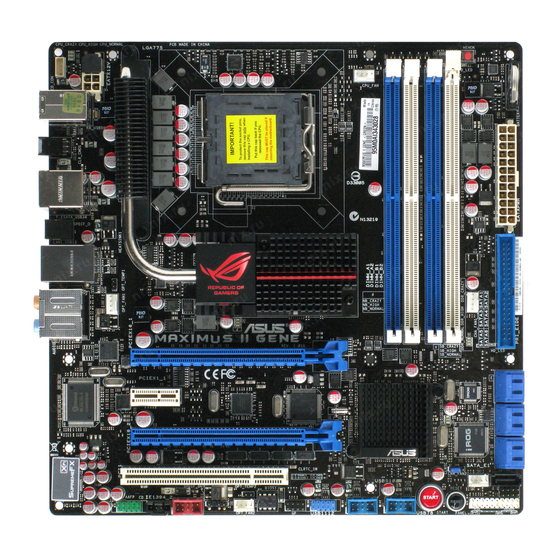
Page 30: Motherboard Overview
Motherboard overview 2.2.1 Motherboard layout Chapter 2: Hardware information... -
Page 31: Layout Contents
IEEE 1394a port connector (10-1 pin IE1394_2) 2-37 Optical drive audio connector (4-pin CD) 2-38 Front panel audio connector (10-1 pin AAFP) 2-38 Refer to 2.7 Connectors for more information about rear panel connectors and internal connectors. ROG Maximus II GENE... -
Page 32: Placement Direction
2.2.3 Placement direction When installing the motherboard, ensure that you place it into the chassis in the correct orientation. The edge with external ports goes to the rear part of the chassis as indicated in the image below. 2.2.4 Screw holes Place eight (8) screws into the holes indicated by circles to secure the motherboard to the chassis. -
Page 33: Central Processing Unit (Cpu)
ASUS will shoulder the cost of repair only if the damage is shipment/transit-related. • Keep the cap after installing the motherboard. ASUS will process Return Merchandise Authorization (RMA) requests only if the motherboard comes with the cap on the LGA775 socket. -
Page 34: Installing The Cpu
2.3.1 Installing the CPU To install a CPU: Locate the CPU socket on the motherboard. Before installing the CPU, ensure that the cam box is facing towards you and the load lever is on your left. Press the load lever with your thumb Retention tab (A), then move it to the left (B) until it is released from the retention tab. - Page 35 The thermal interface material is toxic and inedible. If it gets into your eyes or touches your skin, ensure to wash it off immediately, and seek professional medical help. To prevent contaminating the paste, DO NOT spread the paste with your finger directly. ROG Maximus II GENE 2-11...
- Page 36 Close the load plate (A), then push the load lever (B) until it snaps into the retention tab. ® ® The motherboard supports Intel LGA775 processors with the Intel Enhanced ® Memory 64 Technology (EM64T), Enhanced Intel SpeedStep Technology (EIST), and Hyper-Threading Technology. Refer to the Appendix for more information on these CPU features.
-
Page 37: Installing The Cpu Heatsink And Fan
Push down two fasteners at a time in a diagonal sequence to secure the heatsink and fan assembly in place. Orient the heatsink and fan assembly such that the CPU fan cable is closest to the CPU fan connector. ROG Maximus II GENE 2-13... -
Page 38: Uninstalling The Cpu Heatsink And Fan
Connect the CPU fan cable to the connector on the motherboard labeled CPU_FAN. DO NOT forget to connect the CPU fan connector! Hardware monitoring errors can occur if you fail to plug this connector. 2.3.3 Uninstalling the CPU heatsink and fan To uninstall the CPU heatsink and fan: Disconnect the CPU fan cable from the connector on the motherboard. -
Page 39: System Memory
The figure illustrates the location of the DDR2 DIMM sockets: Recommended memory configurations One DIMM: You may install one memory module in any slot as a single-channel operation. Two DIMMs (dual-channel operation): Four DIMMs (dual-channel operation): ROG Maximus II GENE 2-15... -
Page 40: Memory Configurations
2.4.2 Memory configurations You may install 512MB, 1GB, 2GB and 4GB unbuffered, non-ECC DDR2 DIMMs into the DIMM sockets. • You may install varying memory sizes in Channel A, and Channel B. The system maps the total size of the lower-sized channel for the dual-channel configuration. - Page 41 Maximus II GENE Motherboard Qualified Vendors Lists (QVL) DDR2��2��MH�� capability 2-1200MHz capability -1200MHz capability DIMM socket support (Optional) Timing Vendor Part No. Size Chip NO. Voltage Dimm(Bios) 4096MB Heat-Sink 5-5-5-15 G.SKILL F2-9600CL5D-4GBPI • • • (Kit of 2) Package (800-5-5-5-15) Maximus II GENE Motherboard Qualified Vendors Lists (QVL) DDR2�����MH��...
- Page 42 Maximus II GENE Motherboard Qualified Vendors Lists (QVL) DDR2�����MH�� capability 2-1066MHz capability -1066MHz capability Hynix HYMP564U64FP8-G7 512MB SS HYNIX HY5PS12821FFP-G7 7 • • • KINGMAX KLED48F-A8KI5-EPA 1024MB DS KINGMAX KKA8FEIBF-HJK-18A • • KINGSTON KHX8500D2/ 512 512MB Heat-Sink Package • •...
- Page 43 Maximus II GENE Motherboard Qualified Vendors Lists (QVL) DDR2�8��MH�� capability 2-800MHz capability -800MHz capability Vendor Part No. Size Chip Chip NO. Timing Voltage DIMM socket Brand Dimm(Bios) support (Optional) A-DATA M2OAD6H3J4171Q1E52 2048MB DS A-DATA AD20908A8A-25EG • • • Apacer 78.91G9I.9K5...
- Page 44 Maximus II GENE Motherboard Qualified Vendors Lists (QVL) DDR2�8��MH�� capability 2-800MHz capability -800MHz capability GEIL GB28GB6400C5QC 8192MB(Kitof4) DS GEIL GL2L128M88BA25AB 5-5-5-15 • • • GEIL GE28GB800C4QC 8192MB(Kitof4) DS N/A Heat-Sink Package 4-4-4-12 • • • GEIL GE28GB800C5QC 8192MB(Kitof4) DS N/A...
- Page 45 Maximus II GENE Motherboard Qualified Vendors Lists (QVL) DDR2�8��MH�� capability 2-800MHz capability -800MHz capability Super T800UB1GC4 1024MB Heat-Sink Package • • • Talent Transcend JM800QLU-1G 1024MB Transcend TQ243ECF8 • • • Transcend TS128MLQ64V8U 1024MB ELPIDA E1108ACBG-8E-E • • • Transcend JM800QLU-2G...
- Page 46 Maximus II GENE Motherboard Qualified Vendors Lists (QVL) DDR2����MH�� capability 2-667MHz capability -667MHz capability DIMM socket support Timing (Optional) Vendor Part No. Size Chip Brand Chip NO. Voltage Dimm(Bios) Apacer 78.91G92.9K5 512MB APACER AM4B5708JQJS7E • • • Apacer 78.01G9O.9K5 1024MB...
- Page 47 • C*: Supports four modules inserted into both the yellow and black slots as two pairs of dual-channel memory configuration. Visit the ASUS website at www.asus.com for the latest QVL. ROG Maximus II GENE 2-23...
-
Page 48: Installing A Dimm
2.4.3 Installing a DIMM Ensure to unplug the power supply before adding or removing DIMMs or other system components. Failure to do so may cause severe damage to both the motherboard and the components. Unlock a DIMM socket by DIMM notch pressing the retaining clip outward. -
Page 49: Expansion Slots
IRQ” or that the cards do not need IRQ assignments. Otherwise, conflicts will arise between the two PCI groups, making the system unstable and the card inoperable. Refer to the table on the next page for details. ROG Maximus II GENE 2-25... -
Page 50: Interrupt Assignments
2.5.3 Interrupt assignments Standard interrupt assignments Priority Standard function System Timer Keyboard Controller – Redirect to IRQ#9 Communications Port (COM1)* IRQ Holder for PCI Steering* Reserved Reserved System CMOS/Real Time Clock IRQ Holder for PCI Steering* IRQ Holder for PCI Steering* IRQ Holder for PCI Steering* Reserved Numeric Data Processor... -
Page 51: Pci Slot
2.0 graphic cards complying with the PCI Express specifications. Refer to the figure below for the location of the slots. PCI slot PCI Express 2.0 x16_2 slot PCI Express x1 slot PCI Express 2.0 x16_1 slot ROG Maximus II GENE 2-27... - Page 52 • In single VGA card mode, use first the PCIe 2.0 x16_1 slot for a PCI Express x16 graphics card to get better performance. • In CrossFireX™ mode, use the PCIe 2.0 x16_1 and PCIe 2.0 x16_2 (blue) slots for PCI Express x16 graphics cards to get better performance.
-
Page 53: Jumper
If the system hangs due to overclocking of memory timing or chipset voltage and the power button fails to function, pressing down the clr CMOS switch will shut down the system and clear CMOS simultaneously. ROG Maximus II GENE 2-29... -
Page 54: Connectors
Connectors 2.7.1 Rear panel connectors Rear panel connectors 1. PS/2 keyboard port (purple) 6. IEEE 1394a port 2. USB 2.0 ports 3 and 4 7. External SATA port 3. LAN (RJ-45) port** 8. Optical S.PDIF Out port 4. USB 2.0 ports 5 and 6 9. -
Page 55: Audio I/O Connections
Orange – – Center/Subwoofer Center/Subwoofer Black – Rear Speaker Out Rear Speaker Out Rear Speaker Out Gray – – – Side Speaker Out 2.7.2 Audio I/O connections Audio I/O ports Connect to Headphone and Mic ROG Maximus II GENE 2-31... - Page 56 Connect to Stereo Speakers Connect to 2.1 channel Speakers Connect to 4.1 channel Speakers 2-32 Chapter 2: Hardware information...
- Page 57 Connect to 5.1 channel Speakers Connect to 7.1 channel Speakers ROG Maximus II GENE 2-33...
-
Page 58: Internal Connectors
2.7.2 Internal connectors IDE connector (40-1 pin PRI_EIDE) The onboard IDE connector is for the Ultra DMA 133/100/66 signal cable. There are three connectors on each Ultra DMA 133/100/66 signal cable: blue, black, and gray. Connect the blue connector to the motherboard’s IDE connector, then select one of the following modes to configure your device. - Page 59 Serial ATA hard disk drives. The Serial ATA RAID feature is available only if you are using Windows XP SP1 or later version. ® • When using hot-plug and NCQ, set the Configure SATA as in the BIOS to [AHCI]. See section 3.4.� Storage Configuration for details. ROG Maximus II GENE 2-35...
- Page 60 Never connect a 1394 cable to the USB connectors. Doing so will damage the motherboard! You can connect the USB cable to ASUS Q-Connector (USB, blue) first, and then install the Q-Connector (USB) to the USB connector onboard. The USB cable is purchased separately.
- Page 61 This connector is for an additional Sony/Philips Digital Interface (S/PDIF) port(s). Connect the S/PDIF Out module cable to this connector, then install the module to a slot opening at the back of the system chassis. The S/PDIF module is purchased separately. ROG Maximus II GENE 2-37...
- Page 62 Optical drive audio connector (4-pin CD) These connectors allow you to receive stereo audio input from sound sources such as a CD-ROM, TV tuner, or MPEG card. Front panel audio connector (10-1 pin AAFP) This connector is for a chassis-mounted front panel audio I/O module that supports either HD Audio or legacy AC`97 audio standard.
- Page 63 DO NOT place jumper caps on the fan connectors! If you install two VGA cards, we recommend that you plug the chassis fan cable to the motherboard connector labeled OPT_FAN1/2 for better thermal environment. ROG Maximus II GENE 2-39...
- Page 64 10. Thermal sensor cable connectors (2-pin OPT_TEMP1/2) These connectors are for temperature monitoring. Connect the thermal sensor cables to these connectors and place the other ends to the devices which you want to monitor temperature. The optional fan1/2 can work with the temperature sensors for a better cooling effect.
-
Page 65: Atx Power Connectors
If you want to use two high-end PCI Express x16 cards, use a PSU with 1000W power or above to ensure the system stability. PSU suggested list PSU suggested list SilverStone ST1000 Seasonic SS-600HT Thermaltake W0083RE Thermaltake PUREPower-600AP Silverstone SST-ST75ZF EnerMAX EG701AX-VE (E)(24P) ROG Maximus II GENE 2-41... - Page 66 12. System panel connector (20-8 pin PANEL) This connector supports several chassis-mounted functions. • System power LED (2-pin PLED) This 2-pin connector is for the system power LED. Connect the chassis power LED cable to this connector. The system power LED lights up when you turn on the system power, and blinks when the system is in sleep mode.
- Page 67 13. ASUS Q-Connector (system panel) Use the ASUS Q-Connector to connect/disconnect the chassis front panel cables. To install the ASUS Q-Connector: Connect the front panel cables to the ASUS Q-Connector. Refer to the labels on the Q- Connector to know the detailed pin...
-
Page 68: Onboard Switches
2.7.3 Onboard switches Onboard switches allow you to fine-tune performance when working on a bare or open-case system. This is ideal for overclockers and gamers who continually change settings to enhance system performance. Power-on switch Press the power-on switch to wake/power up the system. Reset switch Press the reset switch to reboot the system. - Page 69 MemOK! switch Press the MemOK! switch to load failsafe settings for memory compatibility and improving system boot success. ROG Maximus II GENE 2-45...
-
Page 70: Installing I/O Shield And Lcd Poster
2.7.4 Installing I/O shield and LCD Poster Install the I/O shield to the Orient the motherboard and install chassis by snapping it in place it to the chassis. Ensure that the from inside. motherboard external ports fit the shield openings. Thread the LCD Poster cable through the back I/O shield opening until the stopper fits the... -
Page 71: Starting Up For The First Time
No VGA detected short beeps One continuous beep followed by four Hardware component failure short beeps At power on, hold down the <Delete> key to enter the BIOS Setup. Follow the instructions in Chapter 3. ROG Maximus II GENE 2-47... -
Page 72: Turning Off The Computer
Turning off the computer 2.9.1 Using the OS shut down function If you are using Windows Vista™: ® Click the Start button then select Shut Down. The power supply should turn off after Windows shuts down. ® If you are using Windows ®... -
Page 73: Chapter 3: Bios Setup
This chapter tells how to change the system settings through the BIOS Setup menus. Detailed descriptions of the BIOS parameters are also provided. BIOS setup... - Page 74 Managing and updating your BIOS ..........3-1 BIOS setup program ..............3-6 Extreme Tweaker menu ............... 3-9 Main menu .................. 3-17 Advanced menu ................. 3-23 Power menu ................3-31 Boot menu .................. 3-37 Tools menu ................. 3-41 Exit menu ..................3-45 ROG Maximus II GENE...
-
Page 75: Managing And Updating Your Bios
® ASUS EZ Flash 2 (Updates the BIOS using a floppy disk or USB flash disk.) ASUS CrashFree BIOS 3 utility: Restores the BIOS using the motherboard support DVD or a USB flash drive when the BIOS file fails or gets corrupted. - Page 76 To update the BIOS through the Internet: Launch the ASUS Update utility from the Windows desktop by clicking Start ® > Programs > ASUS > ASUSUpdate > ASUSUpdate. The ASUS Update main window appears. Select Update BIOS from the Select the ASUS FTP site nearest...
- Page 77 To update the BIOS through a BIOS file: Launch the ASUS Update utility from the Windows desktop by clicking Start ® > Programs > ASUS > ASUSUpdate > ASUSUpdate. The ASUS Update main window appears. Select Update BIOS from a file option from the drop-down menu, then click Next.
-
Page 78: Asus Ez Flash 2 Utility
3.1.2 ASUS EZ Flash 2 utility The ASUS EZ Flash 2 feature allows you to update the BIOS without having to use a DOS-based utility. The EZ Flash 2 utility is built in the BIOS chip so it is accessible by pressing <Alt> + <F2> during the Power-On Self Tests (POST). -
Page 79: Asus Crashfree Bios 3 Utility
3.1.3 ASUS CrashFree BIOS 3 utility The ASUS CrashFree BIOS 3 utility is an auto recovery tool that allows you to restore the BIOS file when it fails or gets corrupted during the updating process. You can restore a corrupted BIOS file using the motherboard support DVD or a USB flash drive that contains the BIOS file. -
Page 80: Bios Setup Program
The BIOS setup screens shown in this section are for reference purposes only, and may not exactly match what you see on your screen. • Visit the ASUS website at www.asus.com to download the latest BIOS file for this motherboard. Chapter 3: BIOS setup... -
Page 81: Bios Menu Screen
At the bottom right corner of a menu screen are the navigation keys for that particular menu. Use the navigation keys to select items in the menu and change the settings. Some of the navigation keys differ from one screen to another. ROG Maximus II GENE... -
Page 82: Menu Items
3.2.4 Menu items The highlighted item on the menu bar displays the specific items for that menu. For example, selecting Main shows the Main menu items. The other items (Advanced, Power, Boot, and Exit) on the menu bar have their respective menu items. -
Page 83: Extreme Tweaker Menu
[Auto] South Bridge 1.5 Voltage [Auto] ******** Please select voltage directly! ******** CPU GTL Reference(0) [Auto] CPU GTL Reference(1) [Auto] CPU GTL Reference(2) [Auto] CPU GTL Reference(3) [Auto] NB GTL Reference(0) [Auto] DDR2 ChA Reference Voltage [Auto] DDR2 ChB Reference Voltage [Auto] North Bridge DDR Reference [Auto] ←→ Select Screen ↑↓ Select Item Read POST Code from LCD Poster/iROG Control Plus +- Change Option Debug Mode [String] F1 General Help Keyboard Tweakit Control [Disabled] F10 Save and Exit ESC Exit CPU Spread Spectrum [Auto] PCIE Spread Spectrum [Auto] v02.61 (C)Copyright 1985-2009, American Megatrends, Inc. ROG Maximus II GENE... -
Page 84: Tuning Mode [Extreme Oc]
3.3.1 Tuning Mode [Extreme OC] The Tuning Mode item is the Extreme Tweaker menu item switch for different purpose. The Extreme OC mode offers the maximum tuning degree of freedom to the extreme. The Gaming mode provides the major tuning settings for system performance boost. -
Page 85: Nb Clock Skew [Auto]
Configuration options: [3 DRAM Clocks] [4 DRAM Clocks]—[11 DRAM Clocks] DRAM RAS# to CAS# Delay [5 DRAM Clocks] Configuration options: [3 DRAM Clocks]—[18 DRAM Clocks] DRAM RAS# Precharge [5 DRAM Clocks] Configuration options: [3 DRAM Clocks]—[18 DRAM Clocks] ROG Maximus II GENE 3-11... - Page 86 DRAM RAS# Activate to Precha [15 DRAM Clocks] Configuration options: [3 DRAM Clocks]—[18 DRAM Clocks] RAS# to RAS# Delay [Auto] Configuration options: [Auto] [1 DRAM Clocks]—[15 DRAM Clocks] Row Refresh Cycle Time [Auto] Configuration options: [Auto] [20 DRAM Clocks] [25 DRAM Clocks]— [65 DRAM Clocks] [70 DRAM Clocks] [80 DRAM Clocks] [85 DRAM Clocks] [105 DRAM Clocks] [132 DRAM Clocks] Write Recovery Time [Auto]...
-
Page 87: Dram Static Read Control [Auto]
Set this item to a higher level for better compatibility or a lower level for better performance. Use the <+> and <-> keys or the numeric keypad to enter the desired value. The values range from 1 to 31. ROG Maximus II GENE 3-13... -
Page 88: Load-Line Calibration [Auto]
Pull-In of CHA/B PH1/2/3/4 [Disabled] [Enabled] Applies enhancement on DRAM Channel A and B, Phase 1 to 5. The number of phases is determined by DRAM frequency and FSB strap. [Disabled] Not allowed to adjust this function. 3.3.18 Load-Line Calibration [Auto] Allows you to select the CPU Load-Line mode. -
Page 89: South Bridge 1.1 Voltage [Auto]
Keyboard TweakIt Control [Disabled] Allows you to enable or disable the keyboard TweakIt control. Configuration options: [Disabled] [Enabled] 3.3.35 CPU Spread Spectrum [Auto] [Disabled] Enhances FSB overclocking ability [Auto] Set to [Auto] for EMI control. ROG Maximus II GENE 3-15... -
Page 90: Pcie Spread Spectrum [Auto]
3.3.36 PCIE Spread Spectrum [Auto] [Disabled] Enhances the PCIE overclocking ability [Auto] Set to [Auto] for EMI control. 3-16 Chapter 3: BIOS setup... -
Page 91: Main Menu
Allows you to set the system time. 3.4.2 System Date [Day xx/xx/xxxx] Allows you to set the system date. 3.4.3 Language [English] Allows you to choose the BIOS language version from the options. Configuration options: [繁體中文] [簡体中文] [日本語] [Français] [Deutsch] [English] ROG Maximus II GENE 3-17... -
Page 92: Sata 1-6
3.4.4 SATA 1–6 While entering Setup, the BIOS automatically detects the presence of Serial ATA devices. There is a separate sub-menu for each SATA device. Select a device item then press <Enter> to display the SATA device information. BIOS SETUP UTILITY Main SATA 1 Select the type of device connected... - Page 93 32-bit double word transfer to the processor. This makes more efficient use of the PCI bus as fewer transactions are needed for the transfer of a particular amount of data. [Disabled] Disable this function. ROG Maximus II GENE 3-19...
-
Page 94: Storage Configuration
3.4.� Storage Configuration The items in this menu allow you to set or change the configurations for the SATA devices installed in the system. Select an item then press <Enter> if you want to configure the item. BIOS SETUP UTILITY Main Set [Compatible Mode] Storage Configuration when Legacy OS (i.e. -
Page 95: Ahci Configuration
S.M.A.R.T. (Self-Monitoring, Analysis and Reporting Technology) is a monitor system. When read/write of your hard disk errors occur, this feature allows the hard disk to report warning messages during the POST. [Enabled] Enable the SMART monitoring feature. [Disabled] Disable the SMART monitoring feature. ROG Maximus II GENE 3-21... -
Page 96: System Information
3.4.7 System Information This menu gives you an overview of the general system specifications. The BIOS automatically detects the items in this menu. BIOS SETUP UTILITY Main BIOS Information Version : 0218 Build Date: 03/19/09 Processor Type : Intel(R) Pentium(R) D CPU 000 @ 2.67GHz Speed : 2133MHz System Memory Usable Size : 1024MB ←→ Select Screen ↑↓ Select Item +- Change Field F1 General Help F10 Save and Exit ESC Exit v02.61 (C)Copyright 1985-2009, American Megatrends, Inc. -
Page 97: Advanced Menu
NOTE: If an invalid Brand String:Intel(R) Pentium(R) D CPU 000 @ ratio is set in CMOS 2.13GHz then actual and Frequency :2.13GHz setpoint values may FSB Speed :1066MHz differ. Cache L1 :128 KB Cache L2 :1024 KB NOTE: Please key in Ratio Status:Unlocked(Min:06, Max:08) ratio numbers directly Ratio Actual Value:8 CPUID :6F1 ←→ Select Screen ↑↓ Select Item CPU Ratio Setting [Auto] F1 General Help C1E Support [Enabled] F10 Save and Exit Max CPUID Value Limit [Disabled] ESC Exit Intel(R) Virtualization Tech [Enabled] CPU TM function [Enabled] Execute Disable Bit [Enabled] Intel(R) SpeedStep(TM) Tech [Enabled] v02.61 (C)Copyright 1985-2009, American Megatrends, Inc. ROG Maximus II GENE 3-23... - Page 98 CPU Ratio Setting [Auto] Allows you to set the ratio between the CPU Core Clock and the FSB Frequency. Use <+> and <-> to adjust the ratio. The valid value ranges differently according to your CPU model. C1E Support [Disabled] [Enabled] Enables the C1E support function.
-
Page 99: Chipset
Enable this option only when you install 64-bit operating system. [Disabled] Disables this function. Initiate Graphic Adapter [PEG/PCI] Allows you to decide which graphics controller to use as the primary boot device. Configuration options: [PCI/PEG] [PEG/PCI] ROG Maximus II GENE 3-25... -
Page 100: Onboard Device Configuration
3.�.3 Onboard Device Configuration BIOS SETUP UTILITY Advanced Onboard Device Configuration Get your best overclocking record! Onboard Device [Standard] “Onboard Device” is to disable all the High Definition Audio [Enabled] unnecessary devices Front Panel Type [HD Audio] when you want to J-Micron eSATA/PATA Controller [Enabled] reach you best Controller Mode [IDE] overclocking record. Onboard PCIEx1 LAN [Enabled] But it will keep 1 LAN Boot ROM [Disabled] lan port alive to Onboard VIA 1394 [Enabled] submit your score. Onboard Device [Standard] Allows you to disable all the onboard device controllers except the LAN controller. -
Page 101: Usb Configuration
The USB 2.0 Controller Mode item appears only when you enable the USB 2.0 Controller. BIOS EHCI Hand-off [Enabled] [Enabled] Enables the support for operating systems without an EHCI hand-off feature. [Disabled] Disables the function. ROG Maximus II GENE 3-27... -
Page 102: Pci Pnp
Legacy USB Support [Auto] [Auto] Allows the system to detect the presence of USB devices at startup. If detected, the USB controller legacy mode is enabled. If no USB device is detected, the legacy USB support is disabled. [Enabled] Enables the support for USB devices on legacy operating systems (OS). -
Page 103: Lcd Poster And Led Control
Configuration options: [Enabled] [Disabled] CPU LED Selection [CPU] Allows you to switch the onboard CPU LED display between CPU voltage [CPU], CPU PLL voltage [CPU PLL] and QPI/DRAM Core voltage [QPI/DRAM Core]. Configuration options: [CPU] [CPU PLL] ROG Maximus II GENE 3-29... -
Page 104: Irog Configuration
NB LED Selection [NB] Allows you to switch the onboard northbridge LED display. Configuration options: [NB] [VTT] SB LED Selection [ICH] Allows you to switch the onboard southbridge LED display. Configuration options: [ICH] [ICH PCIE] 3.�.� iROG Configuration BIOS SETUP UTILITY Advanced iROG Configuration iROG Timer Keeper System will record... -
Page 105: Power Menu
When set to [Enabled], the system invokes VGA BIOS POST on S3/STR resume. 3.6.3 ACPI 2.0 Support [Disabled] [Disabled] When set to [Disabled], the system will not add additional tables as per ACPI 2.0 specifications. ROG Maximus II GENE 3-31... -
Page 106: Apm Configuration
3.6.4 ACPI APIC Support [Enabled] Allows you to enable or disable the Advanced Configuration and Power Interface (ACPI) support in the Advanced Programmable Interrupt Controller (APIC). [Disabled] When set to [Disabled], the system disable the Advanced Configuration and Power Interface (ACPI) support in the Advanced Programmable Interrupt Controller (APIC). - Page 107 Sets specific keys on the PS/2 keyboard to turn on the system. Sets specific keys on the PS/2 keyboard to turn on the system. This feature requires an ATX power supply that provides at least 1A on the +5VSB lead. . ROG Maximus II GENE 3-33...
-
Page 108: Hardware Monitor
3.6.6 Hardware Monitor BIOS SETUP UTILITY Advanced Hardware Monitor Voltage Monitor Voltage Monitor Temperature Monitor Fan Speed Monitor Fan Speed Control ←→ Select Screen ↑↓ Select Item F1 General Help F10 Save and Exit ESC Exit v02.61 (C)Copyright 1985-2009, American Megatrends, Inc. Voltage Monitor CPU Voltage; CPU PLL Voltage; DRAM VTT Voltage; FSB Termination Voltage; North Bridge 1.1 Voltage; South Bridge 1.1 Voltage; South Bridge 1.5 Voltage;... -
Page 109: Fan Speed Control
The CPU Fan Profile item appears when you enable the CPU Fan Control feature. CPU Fan Profile [Standard] Allows you to set the appropriate performance level of the ASUS Q-Fan. [Standard] Set to [Standard] to make the CPU fan Set to [Standard] to make the CPU fan moderately adjust for quiet fan operation. - Page 110 Chassis Fan Profile [Standard] Allows you to set the appropriate performance level of the ASUS Q-Fan. [Standard] Set to [Standard] to make the CPU fan moderately adjust for quiet fan operation. [Silent] Set to [Silent Mode] to minimize the fan speed...
-
Page 111: Boot Menu
These items specify the boot device priority sequence from the available devices. The number of device items that appears on the screen depends on the number of devices installed in the system. Configuration options: [xxx Drive] [Disabled] ROG Maximus II GENE 3-37... -
Page 112: Boot Settings Configuration
Enables the full screen logo display feature. [Disabled] Disables the full screen logo display feature. Set this item to [Enabled] to use the ASUS MyLogo3™ feature. AddOn ROM Display Mode [Force BIOS] Sets the display mode for option ROM. [Force BIOS] [Keep Current] . -
Page 113: Security
<Enter>. The message “Password Uninstalled” appears. If you forget your BIOS password, you can clear it by erasing the CMOS Real Time Clock (RTC) RAM. See section 2.6 Jumper for information on how to erase the RTC RAM. ROG Maximus II GENE 3-39... -
Page 114: Change User Password
After you have set a supervisor password, the other items appear to allow you to change other security settings. BIOS SETUP UTILITY Boot Security Settings <Enter> to change password. Supervisor Password :Installed <Enter> again to User Password :Installed disabled password. Change Supervisor Password User Access Level [Full Access] Change User Password Password Check [Setup] User Access Level [Full Access] This item allows you to select the access restriction to the Setup items. -
Page 115: Tools Menu
3.8.1 ASUS EZ Flash 2 Allows you to run ASUS EZ Flash 2. When you press <Enter>, a confirmation message appears. Use the left/right arrow key to select between [Yes] or [No], then press <Enter> to confirm your choice. -
Page 116: Asus O.c. Profile
3.8.2 ASUS O.C. Profile This item allows you to store or load multiple BIOS settings. BIOS SETUP UTILITY Tools O.C. PROFILE Configuration Typing your profile name, [0-9][a-z][A-Z] O.C. Profile 1 Status : Not Installed are acceptable. O.C. Profile 2 Status : Not Installed O.C. Profile 3 Status : Not Installed O.C. -
Page 117: Tweakit Batch File
Voltage; North Bridge 1.1 Voltage; South Bridge 1.1 Voltage; South Bridge 1.5 Voltage; DRAM Voltage Allows you to use the <+> and <-> keys to adjust the values for each item. Refer to 3.3 Extreme Tweaker Menu for details. ROG Maximus II GENE 3-43... -
Page 118: Ai Net 2
3.8.4 AI NET 2 BIOS SETUP UTILITY Tools Ai Net 2 Check Realtek LAN Pair Status Length cable during POST. It will take 3 to 10 seconds to diagnose Check Realtek LAN cable [Disabled] LAN cable. Check Realtek LAN cable [Disabled] Enables or disables checking of the LAN cable during the Power-On Self-Test (POST). Configuration options: [Disabled] [Enabled] 3-44 Chapter 3: BIOS setup... -
Page 119: Exit Menu
Setup menus. When you select this option or if you press <F5>, a confirmation window appears. Select YES to load default values. Select Exit & Save Changes or make other changes before saving the values to the non-volatile RAM. ROG Maximus II GENE 3-45... - Page 120 3-46 Chapter 3: BIOS setup...
-
Page 121: Chapter 4: Software Support
This chapter describes the contents of the support DVD that comes with the motherboard package and the software. Software support... - Page 122 Chapter summary Installing an operating system ........... 4-1 Support DVD information ............4-1 Software information ..............4-9 RAID configurations ..............4-32 Creating a RAID driver disk ............4-49 ROG Maximus II GENE...
-
Page 123: Installing An Operating System
The contents of the support DVD are subject to change at any time without notice. Visit the ASUS website at www.asus.com for updates. 4.2.1 Running the support DVD Place the support DVD to the optical drive. -
Page 124: Drivers Menu
The drivers menu shows the available device drivers if the system detects installed devices. Install the necessary drivers to activate the devices. ASUS InstAll - Drivers Installation Wizard Launches the ASUS InstAll driver installation wizard. Intel Chipset Inf Update Program Installs the Intel chipset inf update program. -
Page 125: Utilities Menu
ASUS InstAll - Installation Wizard for Utilities Installs all of the utilities through the Installation Wizard. ASUS Update The ASUS Update utility allows you to update the motherboard BIOS in Windows ® environment. This utility requires an Internet connection either through a network or an Internet Service Provider (ISP). - Page 126 Installs the ASUS AI Suite. ASUS AI Direct Link The ASUS AI Direct Link provides up to 70% transferring speed improvement when compared to traditional USB 2.0 and is the easiest and fastest way for users to enjoy large-sized data exchange of files such as movies, music, etc.
-
Page 127: Make Disk Menu
The Manuals menu contains a list of supplementary user manuals. Click an item to open the folder of the user manual. Most user manual files are in Portable Document Format (PDF). Install the Adobe Acrobat Reader from the Utilities menu before opening a user manual ® ® file. ROG Maximus II GENE... -
Page 128: Video Menu
ROG users’ outstanding performances with ROG motherboards. 4.2.7 ASUS Contact information Click the Contact tab to display the ASUS contact information. You can also find this information on the inside front cover of this user guide. Chapter 4: Software support... -
Page 129: Other Information
DVD. Click an icon to display the specified information. Motherboard Info Displays the general specifications of the motherboard. Browse this DVD Displays the support DVD contents in graphical format. ROG Maximus II GENE... -
Page 130: Technical Support Form
Technical support form Displays the ASUS Technical Support Request Form that you have to fill out when requesting technical support. Filelist Displays the contents of the support DVD and a brief description of each in text format. Chapter 4: Software support... -
Page 131: Software Information
4.3.1 ASUS MyLogo3™ The ASUS MyLogo3� utility lets you customize the boot logo. The boot logo is the image that appears on screen during the Power-On Self-Tests (POST). The ASUS MyLogo3™ is automatically installed when you install the ASUS Update utility from the support DVD. - Page 132 Ratio box. When the screen returns to the ASUS Update utility, flash the original BIOS to load the new boot logo. 10. After flashing the BIOS, restart the computer to display the new boot logo during POST.
-
Page 133: Sound Blaster X-Fi Audio Utility
Click Help in each utility control panel to know more about them. Double-click the Volume Panel icon to launch the Mixer control panel. Click Main Display to go to the Main Panel. ROG Maximus II GENE 4-11... -
Page 134: Speakers And Headphone Panel
Main Panel The Main Panel displays all the features and functions the SupremeFX X-Fi supports. Click each icon to configure the following settings (from left to right): Speakers and Headphone, EA� Effects, �-Fi CMSS-3D, �-Fi Crystalizer, Smart Volume Management, Graphic Equalizer, and Mixer. Minimize Exit Help... - Page 135 Click to select Drag to adjust an upmix mode effects (appears when using 4/4.1/5.1/7.1 Speakers) X-Fi Crystalizer Panel Enable �-Fi Crystalizer to obtain more audio dynamics. Drag to adjust Click to enable effects X-Fi Crystalizer ROG Maximus II GENE 4-13...
- Page 136 Smart Volume Management Panel Enable Smart Volume Management (SVM) to avoid large volume fluctuations. Click to switch on/off SVM Graphic Equalizer Panel This panel allows you to customize equalizer settings or select an EQ presets. Click to select Click to an EQ preset enable EQ Click to save...
-
Page 137: Asus Pc Probe Ii
To launch the PC Probe II from the Windows desktop, click Start > All Programs ® > ASUS > PC Probe II > PC Probe II v1.xx.xx. The PC Probe II main window appears. After launching the application, the PC Probe II icon appears in the Windows ®... - Page 138 Button Function Opens the Configuration window Opens the Report window Opens the Desktop Management Interface window Opens the Peripheral Component Interconnect window Opens the Windows Management Instrumentation window Opens the hard disk drive, memory, CPU usage window Shows/Hides the Preference section Minimizes the application Closes the application Sensor alert...
- Page 139 Click to clicking the or buttons. You can increase also adjust the threshold values value using the Config window. Click to You cannot adjust the sensor decrease threshold values in a small value monitoring panel. ROG Maximus II GENE 4-17...
- Page 140 Monitoring sensor alert The monitor panel turns red when a component value exceeds or is lower than the threshold value. Refer to the illustrations below. Small display Large display WMI browser Click to display the WMI (Windows Management Instrumentation) browser. This browser displays various Windows®...
- Page 141 Click a hard disk drive to display the information on the right panel. The pie chart at the bottom of the window represents the used (blue) and the available HDD space. ROG Maximus II GENE 4-19...
- Page 142 Memory usage The Memory tab shows both used and available physical memory. The pie chart at the bottom of the window represents the used (blue) and the available physical memory. Configuring PC Probe II Click to view and adjust the sensor threshold values. The Config window has two tabs: Sensor/Threshold and Preference.
-
Page 143: Asus Ai Suite
4.3.4 ASUS AI Suite ASUS AI Suite allows you to launch EPU-6 Engine, TurboV, CPU Level Up, and Fan Xpert utilities easily. utilities easily. Installing AI Suite To install AI Suite on your computer: Place the support DVD to the optical drive. The Drivers installation tab appears if your computer has an enabled Autorun feature. - Page 144 Other feature buttons Click on right corner of the main window to open the monitor window. Displays the CPU/ system temperature, CPU/memory/PCIE voltage, and CPU/ chassis fan speed Displays the FSB/CPU frequency Click on right corner of the expanded window to switch the temperature from degrees Centigrade to degrees Fahrenheit.
-
Page 145: Asus Fan Xpert
4.3.5 ASUS Fan Xpert Asus Fan Xpert intelligently allows you to adjust both the CPU and chassis fan speeds according to different ambient temperatures caused by different climate conditions in different geographic regions and your PC’s system loading. The built-in variety of useful profiles offer flexible controls of fan speed to achieve a quiet and cool environment. -
Page 146: Fan Profile Modes
Fan profile modes Disable: Select this mode to disable the Fan Xpert function. • • Standard: This mode makes the fan adjust speed in moderate pattern. • Silent: This mode minimizes fan speed for quiet fan operation. Turbo: This mode boosts the fan to achieve maximal fan speed for the best •... -
Page 147: Cpu Level Up
CPU and click the CPU ® Level Up button on the AI Suite main window. Click to select a CPU level Click to apply the Click to exit the selected CPU level utlity ROG Maximus II GENE 4-25... -
Page 148: Asus Epu-6 Engine
4.3.7 ASUS EPU-6 Engine ASUS EPU-6 Engine is an energy-efficient tool that satisfies different computing needs. This utility provides four modes that you can select to enhance system performance or save power. Selecting Auto mode will have the system shift modes automatically according to current system status. -
Page 149: Engine Main Menu
Advanced settings for each mode (refer to the next page for further information) *• Click Current to show the CO2 that has been reduced since you click the Renew button *• Click Total to show the total CO2 that has been reduced since you launched 6 Engine. ROG Maximus II GENE 4-27... -
Page 150: Advanced Settings Menu
Advanced settings menu Click Setting ( ) from the 6 Engine main menu to display configuration options in each mode. Some options in certain modes are dimmed, meaning that they are not available. Click to select a mode Move the slider to adjust Click the arrow to see more... - Page 151 6-Engine to other mode option. Or, you may click the TweakIt icon in the Windows notification area ® and click Unlock to enable the TweakIt function. Ensure that you’ve installed TweakIt driver from the bundled Support DVD. ROG Maximus II GENE 4-29...
-
Page 152: Asus Turbov
• For system stability, all changes made in ASUS TurboV will not be saved to BIOS settings and will not be kept on the next system boot. Use the Save Profile function to save your customized overclocking settings and manually load the profile after Windows starts. - Page 153 Advanced settings menu Click More Setting from the TurboV main screen to display detailed configuration options for CPU/chip voltage, DRAM Reference voltage, and CPU ratio. Advance Mode Advanced CPU and DRAM voltage settings ROG Maximus II GENE 4-31...
-
Page 154: Raid Configurations
RAID configurations The motherboard comes with the Intel ICH10R Southbridge controller that ® supports RAID 0, RAID 1, RAID 10, and RAID 5 for six independent Serial ATA channels. 4.4.� RAID definitions RAID 0 (Data striping) optimizes two identical hard disk drives to read and write data in parallel, interleaved stacks. -
Page 155: Installing Serial Ata Hard Disks
Go to the Main menu > Storage Configuration, and then press <Enter>. Set the Configure SATA as item to [RAID]. Save your changes, and then exit the BIOS Setup. Refer to Chapter 3 for details on entering and navigating through the BIOS Setup. ROG Maximus II GENE 4-33... -
Page 156: Intel ® Matrix Storage Manager Option Rom Utility
4.4.4 Intel Matrix Storage Manager option ROM utility ® The Intel Matrix Storage Manager Option ROM utility allows you to create RAID 0, ® RAID 1, RAID 10 (RAID 0+1), and RAID 5 set(s) from Serial ATA hard disk drives that are connected to the Serial ATA connectors supported by the Southbridge. -
Page 157: Creating A Raid Set
1 ST3160812AS 9LS0F4HL 149.0GB Non-RAID Disk 2 ST3160812AS 3LS0JYL8 149.0GB Non-RAID Disk 3 ST3160812AS 9LS0BJ5H 149.0GB Non-RAID Disk Select 2 to 6 disks to use in creating the volume. [ ↑↓ ]-Prev/Next [SPACE]-SelectDisk [ENTER]-Done Use the up/down arrow key to select a drive, and then press <Space> to select. A small triangle marks the selected drive. Press <Enter> after completing your selection ROG Maximus II GENE 4-35... - Page 158 Use the up/down arrow key to select the stripe size for the RAID array (for RAID 0, 10 and 5 only), and then press <Enter>. The available stripe size values range from 4 KB to 128 KB. The following are typical values: RAID 0: 128KB RAID 10: 64KB RAID 5: 64KB...
-
Page 159: Deleting A Raid Set
<Del>. The following warning message appears. [ DELETE VOLUME VERIFICATION ] ALL DATA IN THE VOLUME WILL BE LOST! Are you sure you want to delete volume “Volume0”? (Y/N): Press <Y> to delete the RAID set and return to the utility main menu, or press <N> to return to the DELETE VOLUME menu. ROG Maximus II GENE 4-37... - Page 160 Exiting the Intel Matrix Storage Manager ® To exit the utility From the utility main menu, select 4. Exit, and then press <Enter>. The following warning message appears. [ CONFIRM EXIT ] Are you sure you want to exit? (Y/N): Press <Y> to exit or press <N> to return to the utility main menu. 4-38 Chapter 4: Software support...
-
Page 161: Creating A Raid Driver Disk
Driver Disk to create an Intel ICH10R RAID driver disk. ® Insert a floppy disk into the floppy disk drive. Follow the succeeding screen instructions to complete the process. Write-protect the floppy disk to avoid computer virus infection. ROG Maximus II GENE 4-39... - Page 162 To install the RAID driver in Windows ® During the OS installation, the system prompts you to press the F6 key to install third-party SCSI or RAID driver. Press <F6>, and then insert the floppy disk with RAID driver into the floppy disk drive.
-
Page 163: Chapter 5: Multiple Gpu Technology Support
This chapter describes how to install and configure multiple ATI CrossFireX™ ® graphics cards. Multiple GPU technology support... - Page 164 Chapter summary CrossFireX™ technology ............ 5-1 ® ROG Maximus II GENE...
-
Page 165: Ati ® Crossfirex™ Technology
For Windows XP, go to Control Panel > Add/Remove Programs. For Windows Vista, go to Control Panel > Programs and Features. Select your current graphics card driver/s. For Windows XP, select Add/Remove. For Windows Vista, select Uninstall. Turn off your computer. ROG Maximus II GENE... -
Page 166: Installing Crossfirex Graphics Cards
5.1.3 Installing CrossFireX graphics cards The following pictures are for reference only. The graphics cards and the motherboard layout may vary with models, but the installation steps remain the same. Prepare two CrossFireX-ready graphics cards. Insert the two graphics card into the PCIEX16 slots. -
Page 167: Installing The Device Drivers
Windows notification area and select Cayalist Control Center. The Catalyst Control Center Setup Assistant appears when the system detects the existance of multi- graphics cards. Click Go to continue to the Catalyst Control Center Advanced View window. ROG Maximus II GENE... - Page 168 Enabling CrossFireX settings In the Catalyst Control Center window, click Graphics Settings > CrossFireX > Configure. From the Graphics Adapter list, select the graphics card to act as the display GPU. Select Enable CrossFireX. Click Apply, and then click OK to exit the window.
- Page 169 The Appendix lists the debug code table for the LCD Poster. Debug code table Appendix:...
- Page 170 Chapter summary Debug code table ..................A-1 ROG Maximus II GENE...
- Page 171 4. Measure CPU speed. 5. Invoke video BIOS. VGA BIOS Initialize VGA BIOS 1. Initialize multi-language TESTVRAM 2. Put information on screen display, including BIOS logo, CPU type, CPU speed . RESET KB Reset keyboard. ROG Maximus II GENE...
- Page 172 Debug code table Code Description 8254TEST Test 8254 8259MSK1 Test 8259 interrupt mask bits for channel 1. 8259MSK2 Test 8259 interrupt mask bits for channel 2. 8259TEST Test 8259 functionality. COUNTMEM Calculate total memory by testing the last double word of each 64K page. 1.
- Page 173 Boot attempt (INT 19h) Manufacturer ASUSTek COMPUTER INC. Address, City No. 15, LI-TE RD., PEITOU, TAIPEI 112, TAIWAN R.O.C Country TAIWAN Authorized Representative in Europe ASUS COMPUTER GmbH Address, City HARKORT STR. 21-23, 40880 RATINGEN Country GERMANY ROG Maximus II GENE...
-
Page 174: Appendix: Debug Code Table
Appendix: Debug code table...
Need help?
Do you have a question about the Maximus II Gene and is the answer not in the manual?
Questions and answers