Table of Contents
Advertisement
Advertisement
Table of Contents

Related Manuals for Asus M4N78 SE


Summary of Contents for Asus M4N78 SE
- Page 1 M4N78 SE...
- Page 2 Product warranty or service will not be extended if: (1) the product is repaired, modified or altered, unless such repair, modification of alteration is authorized in writing by ASUS; or (2) the serial number of the product is defaced or missing.
-
Page 3: Table Of Contents
Contents Notices ......................vi Safety information ..................vii About this guide ..................vii M4N78 SE specifications summary ............ix Chapter 1: Product introduction Welcome! ..................1-1 Package contents ................. 1-1 Special features ................1-1 1.3.1 Product highlights ............1-1 1.3.2 Innovative ASUS features .......... - Page 4 BIOS information Managing and updating your BIOS ..........2-1 2.1.1 ASUS Update utility ............2-1 2.1.2 ASUS EZ Flash 2 utility ........... 2-2 2.1.3 ASUS CrashFree BIOS 3 utility ........2-3 BIOS setup program ..............2-4 2.2.1 BIOS menu screen ............2-5 2.2.2...
- Page 5 Boot Device Priority ............2-17 2.6.2 Boot Settings Configuration .......... 2-17 2.6.3 Security ................. 2-18 Tools menu ................. 2-19 2.7.1 ASUS EZ Flash 2 ............2-19 2.7.2 Express Gate ............... 2-20 2.7.3 AI NET 2................ 2-20 Exit menu ..................2-21...
-
Page 6: Notices
Notices Federal Communications Commission Statement This device complies with Part 15 of the FCC Rules. Operation is subject to the following two conditions: • This device may not cause harmful interference, and • This device must accept any interference received including interference that may cause undesired operation. -
Page 7: Safety Information
Safety information Electrical safety • To prevent electrical shock hazard, disconnect the power cable from the electrical outlet before relocating the system. • When adding or removing devices to or from the system, ensure that the power cables for the devices are unplugged before the signal cables are connected. If possible, disconnect all power cables from the existing system before you add a device. -
Page 8: Conventions Used In This Guide
Refer to the following sources for additional information and for product and software updates. ASUS websites The ASUS website provides updated information on ASUS hardware and software products. Refer to the ASUS contact information. Optional documentation Your product package may include optional documentation, such as warranty flyers, that may have been added by your dealer. -
Page 9: M4N78 Se Specifications Summary
2 x 240-pin DIMM slots support unbuffered ECC and non-ECC DDR2 1066/800/667MHz memory modules Supports up to 8GB system memory Refer to www.asus.com for the latest Memory QVL (Qualified Vendors List). ** Due to the memory address limitation on 32-bit... - Page 10 M4N78 SE specifications summary ASUS special features ASUS Quiet Thermal Solution - ASUS Q-Fan ASUS EZ DIY - ASUS CrashFree BIOS3 - ASUS EPU 4-Engine - ASUS EZ Flash2 ASUS Express Gate Turbo key ASUS AI NAP ASUS AI NET 2...
-
Page 11: Chapter 1: Product Introduction
® The motherboard delivers a host of new features and latest technologies, making it another standout in the long line of ASUS quality motherboards! Before you start installing the motherboard, and hardware devices on it, check the items in your package with the list below. -
Page 12: High Definition Audio
NVIDIA nForce™ 720D chipset ® The NVIDIA nForce 720D supports HyperTransport™3.0 interface, ® PCI Express™ 2.0 bus architecture, and Serial ATA 3 GB/s devices. It is optimized with AMD’s latest AM2+ and multi-core CPUs to provide excellent system performance. HyperTransport 3.0 support 5200 HyperTransport 3.0 technology provides 2.6 times more bandwidth than MT/s... -
Page 13: Innovative Asus Features
BIOS file using the bundled support DVD, or USB disk that contains the BIOS file. ASUS EZ Flash 2 ASUS EZ Flash 2 is a utility that allows you to update the BIOS without using a bootable floppy disk or an OS-based utility. ASUS Express Gate With on 5 seconds boot-up time, the ASUS Express Gate allows you to instantly surf the Internet without entering Windows or the Hard Disk. -
Page 14: Before You Proceed
Before you proceed Take note of the following precautions before you install motherboard components or change any motherboard settings. • Unplug the power cord from the wall socket before touching any component. • Use a grounded wrist strap or touch a safely grounded object or a metal object, such as the power supply case, before handling components to avoid damaging them due to static electricity •... -
Page 15: Motherboard Overview
Screw holes Place six screws into the holes indicated by circles to secure the motherboard to the chassis. Do not overtighten the screws! Doing so can damage the motherboard. Place this side towards the rear of the chassis. ASUS M4N78 SE... -
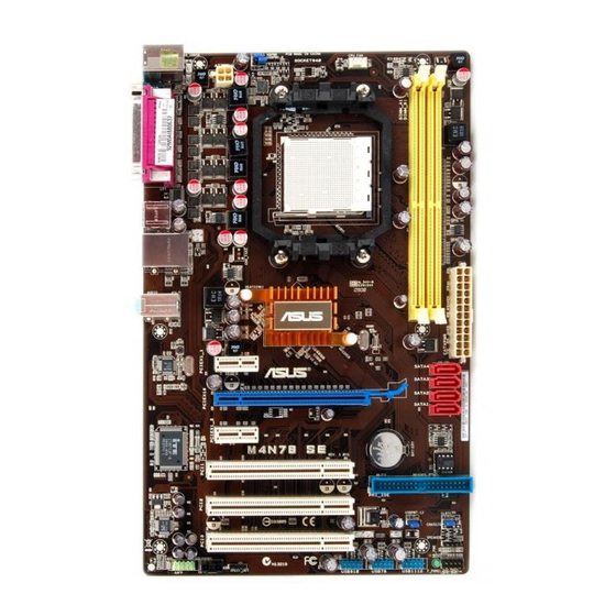
Page 16: Motherboard Layout
1.5.3 Motherboard layout 1.5.4 Layout contents Connectors/Jumpers/Slots Page Connectors/Jumpers/Slots Page 1. ATX power connectors (24-pin EATXPWR, 4-pin ATX12V) 1-21 9. Clear RTC RAM (3-pin CLRTC) 1-18 2. Keyboard power (3-pin KBPWR) 1-19 10. Speaker (4-pin SPEAKER) 1-24 3. USB device wake-up (3-pin USBPW1-6, USBPW7-12) 1-19 11. -
Page 17: Central Processing Unit (Cpu)
Carefully insert the CPU into the socket until it fits in place. The CPU fits only in one correct orientation. DO NOT force the CPU into the socket to prevent bending the pins and damaging the CPU. Gold triangle Small triangle ASUS M4N78 SE... - Page 18 When the CPU is in place, push down the socket lever to secure the CPU. The lever clicks on the side tab to indicate that it is locked. Install a CPU heatsink and fan following the instructions that came with the heatsink package.
-
Page 19: Installing The Heatsink And Fan
Your boxed CPU heatsink and fan assembly should come with installation instructions for the CPU, heatsink, and the retention mechanism. If the instructions in this section do not match the CPU documentation, follow the latter. Attach one end of the retention bracket to the retention module base. ASUS M4N78 SE... -
Page 20: System Memory
Align the other end of the retention bracket to the retention module base. A clicking sound denotes that the retention bracket is in place. Ensure that the fan and heatsink assembly perfectly fits the retention mechanism module base, otherwise you cannot snap the retention bracket in place. Push down the retention bracket lock on the retention mechanism to secure the heatsink and fan to the module base. -
Page 21: Memory Configurations
The motherboard supports up to 8GB memory modules on Windows XP Professional x64 ® and Vista x64 editions. You may install a maximum of 4 GB DIMMs on each slot. M4N78 SE Motherboard Qualified Vendors Lists (QVL) DDR2-667MHz capability DIMM support Chip... - Page 22 DDR2-667MHz capability DIMM support Chip Size Vendor Part No. Chip No. Brand Apacer 78.01G9O.9K5 AM4B5808CQJS7E0751C Apacer · · Apacer AU01GE667C5KBGC AM4B5708GQJS7E0636B Apacer · · Apacer AU01GE667C5KBGC AM4B5708MIJS7E0627B Apacer · · Apacer 78.A1G9O.9K4 AM4B5808CQJS7E0749B Apacer · · Transcend 506010-4894 E5108AJBG-6E-E Elpida ·...
- Page 23 Transcend TS128MLQ64V8U E1108ACBG-8E-E Elpida · · Transcend JM800QLU-2G TQ243PCF8 Transcend · · Transcend TS256MLQ64V8U E1108ACBG-8E-E Elpida · · ADATA M2OAD6G314170Q1E58 AD29608A8A-25EG80810 ADATA · · 512MB VDATA M2GVD6G3H3160Q1E52 VD29608A8A-25EG20813 VDATA · · (continued on the next page) ASUS M4N78 SE 1-13...
- Page 24 DDR2-800 MHz capability DIMM support Chip Size Vendor Part No. Chip No. Brand AL8E8F73C-8E1 A3R1GE3CFF734MAA0E · · PL8E8F73C-8E1 SHG772-AA3G · · PL8E8G73E-8E1 XCP271A3G-A · · AL7E8E63H-10E1K A3R1GE3CFF750RABBP(ECC) · · GEIL GB22GB6400C4DC GL2L64M088BA30EB GEIL · · GEIL GB24GB6400C4QC GL2L64M088BA30EB GEIL · ·...
- Page 25 • A*: Supports one module inserted into any slot as Single-channel memory configuration. • B*: Supports one pair of modules inserted into the yellow slots as one pair of Dual-channel memory configuration. Visit the ASUS website for the latest DDR2-667/800/1066MHz QVL. ASUS M4N78 SE 1-15...
-
Page 26: Installing A Dimm
1.7.3 Installing a DIMM Unplug the power supply before adding or removing DIMMs or other system components. Failure to do so can cause severe damage to both the motherboard and the components. Press the retaining clips outward to DDR2 DIMM notch unlock a DDR2 DIMM socket. -
Page 27: Expansion Slots
This motherboard supports PCI Express x1 network cards, SCSI cards, and other cards that comply with the PCI Express specifications. 1.8.5 PCI Express x16 slot This motherboard supports a PCI Express x16 graphics card that complies with the PCI Express specifications. ASUS M4N78 SE 1-17... -
Page 28: Jumpers
Jumpers Clear RTC RAM (CLRTC) This jumper allows you to clear the Real Time Clock (RTC) RAM in CMOS. You can clear the CMOS memory of date, time, and system setup parameters by erasing the CMOS RTC RAM data. The onboard button cell battery powers the RAM data in CMOS, which include system setup information such as system passwords. - Page 29 Set to +5VSB to wake up from S3 and S4 sleep modes (no power to CPU, DRAM in slow refresh, power supply in reduced power mode). These jumpers are for the rear and internal USB connectors that you can connect to additional USB ports. ASUS M4N78 SE 1-19...
-
Page 30: Connectors
1.10 Connectors 1.10.1 Rear panel connectors PS/2 keyboard port (purple). This port is for a PS/2 keyboard. Parallel port. This 25-pin port connects a parallel printer, a scanner, or other devices. LAN (RJ-45) port. This port allows Gigabit connection to a Local Area Network (LAN) through a network hub. -
Page 31: Internal Connectors
The system may become unstable or may not boot up if the power is inadequate. • If you are uncertain about the minimum power supply requirement for your system, refer to the Recommended Power Supply Wattage Calculator at http://support.asus. com/PowerSupplyCalculator/PSCalculator.aspx?SLanguage=en-us for details. ASUS M4N78 SE... - Page 32 IDE connector (40-1 pin PRI_IDE) The onboard IDE connector is for Ultra DMA 133/100/66 signal cable. There are three connectors on each Ultra DMA 133 / 100 / 66 signal cable: blue, black, and gray. Connect the blue connector to the motherboard’s IDE connector, then select one of the following modes to configure your devices: Drive jumper setting Mode of device(s)
- Page 33 Mode select item in the BIOS to [RAID Mode]. See page 2-8 for details. Optical drive audio in connector (4-pin CD) This connector allows you to receive stereo audio input from sound sources such as a CD-ROM, TV tuner, or MPEG card. ASUS M4N78 SE 1-23...
-
Page 34: System Panel Connector
System panel connector (10-1 pin F_PANEL) This connector supports several chassis-mounted functions. System power LED (2-pin PWRLED) • This 2-pin connector is for the system power LED. Connect the chassis power LED cable to this connector. The system power LED lights up when you turn on the system power, and blinks when the system is in sleep mode. - Page 35 • By default, this connector is set to [HD Audio]. If you want to connect a High Definition front panel audio module to this connector, set the Front Panel Select item in the BIOS to [HD Audio]. See section “2.4.3 Chipset” for details. ASUS M4N78 SE 1-25...
-
Page 36: Software Support
The contents of the Support DVD are subject to change at any time without notice. Visit the ASUS website at www.asus.com for updates. To run the Support DVD Place the Support DVD to the optical drive. -
Page 37: Chapter 1: Bios Information
BIOS information Managing and updating your BIOS 2.1.1 ASUS Update utility The ASUS Update is a utility that allows you to manage, save, and update the motherboard BIOS in Windows environment. ® • ASUS Update requires an Internet connection either through a network or an Internet Service Provider (ISP). -
Page 38: Asus Ez Flash 2 Utility
2.1.2 ASUS EZ Flash 2 utility The ASUS EZ Flash 2 feature allows you to update the BIOS without having to use an OS-based utility. Before using this utility, download the latest BIOS file from the ASUS website at www.asus. -
Page 39: Asus Crashfree Bios 3 Utility
2.1.3 ASUS CrashFree BIOS 3 utility The ASUS CrashFree BIOS 3 is an auto recovery tool that allows you to restore the BIOS file when it fails or gets corrupted during the updating process. You can update a corrupted BIOS file using the motherboard support DVD or a USB flash disk that contains the updated BIOS file. -
Page 40: Bios Setup Program
The BIOS setup screens shown in this section are for reference purposes only, and may not exactly match what you see on your screen. • Visit the ASUS website at www.asus.com to download the latest BIOS file for this motherboard. -
Page 41: Bios Menu Screen
• The BIOS setup screens shown in this chapter are for reference purposes only, and may not exactly match what you see on your screen. • Visit the ASUS website at www.asus.com to download the latest BIOS information. ASUS M4N78 SE... -
Page 42: Navigation Keys
2.2.3 Navigation keys At the bottom right corner of a menu screen are the navigation keys for that particular menu. Use the navigation keys to select items in the menu and change the settings. Some of the navigation keys differ from one screen to another. 2.2.4 Menu items The highlighted item on the menu bar displays the specific items for that menu. -
Page 43: Main Menu
IDE device type. Select [CDROM] if you are specifically configuring a CD-ROM drive. Select [ARMD] (ATAPI Removable Media Device) if your device is either a ZIP, LS-120, or MO drive. Configuration options: [Not Installed] [Auto] [CDROM] [ARMD] This item does not appear when you select the SATA 1/2/3/4 devices. ASUS M4N78 SE... -
Page 44: Storage Configuration
LBA/Large Mode [Auto] Enables or disables the LBA mode. Setting to [Auto] enables the LBA mode if the device supports this mode, and if the device was not previously formatted with LBA mode disabled. Configuration options: [Disabled] [Auto] Block (Multi-Sector Transfer) M [Auto] Enables or disables data multi-sectors transfers. -
Page 45: System Information
Select either one of the preset overclocking. • Manual - Allows you to individually set overclocking parameters. • Auto - Loads the optimal settings for the system. • Overclock Profile - Loads overclocking profiles with optimal parameters for stability when overclocking. ASUS M4N78 SE... - Page 46 The following item appears only when the CPU Overclocking item is set to [Manual]. CPU Frequency [200] Allows you to set the CPU frequency. The valid value is from 200 MHz to 550 MHz. The following item appears only when the CPU Overclocking item is set to [Overclock Profile].
- Page 47 Allows you to set the memory over voltage. The value ranges from 1.85000V to 2.24375V with a 0.00625V interval. Press +/- to adjust the value. Chipset Voltage [Auto] Allows you to set the chipset voltage. Configuration options: [Auto] [+50mv] [+100mv] [+150mv] ASUS M4N78 SE 2-11...
-
Page 48: Cpu Configuration
2.4.2 CPU Configuration The items in this menu show the CPU-related information that the BIOS automatically detects. GART Error Reporting [Disabled] This option should remain disabled for the normal operation. The driver developer may enable it for testing purpose. Configuration options: [Disabled] [Enabled] Microcode Updation [Enabled] Allows you to enable or disable the microcode updation. -
Page 49: Onboard Devices Configuration
Parallel Port Address [378] Allows you to select the Parallel Port base addresses. Configuration options: [Disabled] [378] [278] [3BC] Parallel Port Mode [Normal] Allows you to select the Parallel Port mode. Configuration options: [Normal] [EPP] [ECP] [EPP+ECP] ASUS M4N78 SE 2-13... -
Page 50: Pci Pnp
2.4.5 PCI PnP The PCI PnP menu items allow you to change the advanced settings for PCI/PnP devices. The menu includes setting IRQ and DMA channel resources for either PCI/PnP or legacy ISA devices, and setting the memory size block for legacy ISA devices. Take caution when changing the settings of the PCI PnP menu items. -
Page 51: Power Menu
When set to [Enabled], this parameter allows you to turn on the system through a PCI/PCIE card. This feature requires an ATX power supply that provides at least 1A on the +5VSB lead. Configuration options: [Disabled] [Enabled] ASUS M4N78 SE 2-15... -
Page 52: Hardware Monitor
The onboard hardware monitor automatically detects the voltage output through the onboard voltage regulators. Smart Q-Fan Function [Disabled] Allows you to enable or disable the ASUS Q-Fan feature that smartly adjusts the fan speeds for more efficient system operation. Configuration options: [Disabled] [Enabled] 2-16... -
Page 53: Boot Menu
This allows you to enable or disable the full screen logo display feature. Configuration options: [Disabled] [Enabled] Set this item to [Enabled] to use the ASUS MyLogo 2™ feature. AddOn ROM Display Mode [Force BIOS] Sets the display mode for option ROM. Configuration options: [Force BIOS]... -
Page 54: Security
Wait for ‘F1’ If Error [Enabled] When set to Enabled, the system waits for the F1 key to be pressed when error occurs. Configuration options: [Disabled] [Enabled] Hit ‘DEL’ Message Display [Enabled] When set to Enabled, the system displays the message Press DEL to run Setup during POST. -
Page 55: Tools Menu
(C)Copyright 1985-2007, American Megatrends, Inc. 2.7.1 ASUS EZ Flash 2 Allows you to run ASUS EZ Flash 2. When you press <OK>, a confirmation message appears. Use the left/right arrow key to select between [Yes] or [No], then press <OK> to confirm your choice. -
Page 56: Express Gate
2.7.2 Express Gate [Auto] Allows you to enable or disable the ASUS Express Gate feature. The ASUS Express Gate feature is a unique instant-on environment that provides quick access to the Internet browser and Skype. Configuration options: [Disabled] [Enabled] [Auto] Enter OS Timer [10 Seconds] Allows you to set the countdown duration that the system waits at the Express Gate’s first... -
Page 57: Exit Menu
When you select this option or if you press <F5>, a confirmation window appears. Select OK to load default values. Select Exit & Save Changes or make other changes before saving the values to the non-volatile RAM. ASUS M4N78 SE 2-21... - Page 58 2-22 Chapter 2: BIOS information...
Need help?
Do you have a question about the M4N78 SE and is the answer not in the manual?
Questions and answers