Table of Contents
Advertisement
Advertisement
Table of Contents

Related Manuals for Asus M2N-X PLUS


Summary of Contents for Asus M2N-X PLUS
- Page 1 M2N-X PLUS...
- Page 2 Product warranty or service will not be extended if: (1) the product is repaired, modified or altered, unless such repair, modification of alteration is authorized in writing by ASUS; or (2) the serial number of the product is defaced or missing.
-
Page 3: Table Of Contents
Contents Notices ......................vi Safety information ..................vii About this guide ..................viii M2N-X PLUS specifications summary ............x Chapter 1: Product introduction Welcome! ..................1-2 Package contents ................. 1-2 Special features ................1-2 1.3.1 Product highlights ............1-2 1.3.2 Innovative ASUS features .......... - Page 4 Creating a bootable floppy disk ........2-2 2.1.2 ASUS EZ Flash utility ............2-3 2.1.3 AFUDOS utility ..............2-4 2.1.4 ASUS CrashFree BIOS 2 utility ........2-6 2.1.5 ASUS Update utility ............2-8 BIOS setup program ..............2-11 2.2.1 BIOS menu screen ............2-12 2.2.2...
- Page 5 Running the support CD ..........3-2 3.2.2 Drivers menu ..............3-3 3.2.3 Utilities menu ..............3-4 3.2.4 Make Disk menu ............. 3-5 3.2.5 Manual menu ..............3-6 3.2.6 ASUS Contact information ..........3-7 3.2.7 Other information ............3-7 Creating a RAID driver disk ............3-9...
-
Page 6: Notices
Notices Federal Communications Commission Statement This device complies with Part 15 of the FCC Rules. Operation is subject to the following two conditions: • This device may not cause harmful interference, and • This device must accept any interference received including interference that may cause undesired operation. -
Page 7: Safety Information
Safety information Electrical safety • To prevent electrical shock hazard, disconnect the power cable from the electrical outlet before relocating the system. • When adding or removing devices to or from the system, ensure that the power cables for the devices are unplugged before the signal cables are connected. If possible, disconnect all power cables from the existing system before you add a device. -
Page 8: About This Guide
Refer to the following sources for additional information and for product and software updates. 1. ASUS websites The ASUS website provides updated information on ASUS hardware and software products. Refer to the ASUS contact information. 2. Optional documentation Your product package may include optional documentation, such as warranty flyers, that may have been added by your dealer. -
Page 9: Conventions Used In This Guide
Conventions used in this guide To ensure that you perform certain tasks properly, take note of the following symbols used throughout this manual. DANGER/WARNING: Information to prevent injury to yourself when trying to complete a task. CAUTION: Information to prevent damage to the components when trying to complete a task. -
Page 10: M2N-X Plus Specifications Summary
Stepless Frequency Selection (SFS): - HT LINK frequency tuning from 200MHz up to 300 MHz at 1MHz increment Profile Overclocking Protection: - ASUS C.P.R. (CPU Parameter Recall) Special features ASUS EZ DIY: - ASUS CrashFree BIOS 2 - ASUS EZ Flash ASUS Install ASUS MyLogo™... - Page 11 M2N-X PLUS specifications summary Manageability Supports up to 10 USB 2.0 / 1.1 ports (6 on board and 4 on back) BIOS features 8 Mb Flash ROM, AMI BIOS, PnP, DMI, Wfm 2.0, ACPI 2.0a, SM BIOS 2.5, CPU Multiplier...
-
Page 13: Chapter 1: Product Introduction
This chapter describes the motherboard features and the new technologies it supports. Product introduction... -
Page 14: Welcome
® The motherboard delivers a host of new features and latest technologies, making it another standout in the long line of ASUS quality motherboards! Before you start installing the motherboard, and hardware devices on it, check the items in your package with the list below. - Page 15 The motherboard implements the Universal Serial Bus (USB) 2.0 specification, dramatically increasing the connection speed from the 12 Mbps bandwidth on USB 1.1 to a fast 480 Mbps on USB 2.0. USB 2.0 is backward compatible with USB 1.1. See page 1-27 for details. ASUS M2N-X PLUS...
-
Page 16: Innovative Asus Features
Green ASUS This motherboard and its packaging comply with the European Union’s Restriction on the use of Hazardous Substances (RoHS). This is in line with the ASUS vision of creating environment-friendly and recyclable products/packaging to safeguard consumers’ health while minimizing the impact on the environment. -
Page 17: Before You Proceed
The illustration below shows the location of the onboard LED. SB_PWR M2N-X PLUS Standby Powered Power M2N-X PLUS Onboard LED ASUS M2N-X PLUS... -
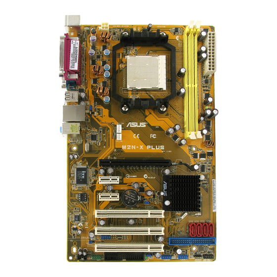
Page 18: Motherboard Overview
Motherboard overview 1.5.1 Motherboard layout 19.3cm(7.6in) PS/2KBMS T: Mouse B: Keyboard ATX12V COM1 USB34 LAN_USB12 AUDIO Attansic M2N-X PLUS PCIEX16 PCIEX1_1 Nvidia MCP61P CR2032 3V PCIEX1_2 Lithium Cell BIOS CMOS Power CLRTC PCI1 ALC662 PCI2 USB56 USBPW56 PCI3 PRI_IDE USBPW7-10... -
Page 19: Placement Direction
Place six (6) screws into the holes indicated by circles to secure the motherboard to the chassis. Do not overtighten the screws! Doing so can damage the motherboard. Place this side towards the rear of the chassis M2N-X PLUS ASUS M2N-X PLUS... -
Page 20: Central Processing Unit (Cpu)
1.6.1 Installing the CPU To install a CPU: Locate the CPU socket on the motherboard. M2N-X PLUS M2N-X PLUS CPU Socket AM2+ Unlock the socket by pressing the lever sideways, then lift it up to a 90°-100° angle. Socket lever Ensure that the socket lever is lifted up to 90°-100°... - Page 21 CPU FAN PWM M2N-X PLUS CPU FAN IN CPU FAN PWR M2N-X PLUS CPU Fan Connector Do not forget to connect the CPU fan connector! Hardware monitoring errors can occur if you fail to plug this connector. ASUS M2N-X PLUS...
-
Page 22: Installing The Heatsink And Fan
1.6.2 Installing the heatsink and fan The AMD Athlon™ 64 X2 / Athlon™ 64 / Athlon™ FX / Sempron™ processor require a specially designed heatsink and fan assembly to ensure optimum thermal condition and performance. Ensure that you use only qualified heatsink and fan assembly. Follow these steps to install the CPU heatsink and fan: Place the heatsink on top of the installed CPU, making sure that the heatsink fits properly on the retention module base. - Page 23 Otherwise, you cannot snap the retention bracket in place. Push down the retention bracket lock on the retention mechanism to secure the heatsink and fan to the module base. ASUS M2N-X PLUS 1-11...
-
Page 24: System Memory
240-pin footprint compared to the 184-pin DDR DIMM. DDR2 DIMMs are notched differently to prevent installation on a DDR DIMM socket. The figure illustrates the location of the DDR2 DIMM sockets: M2N-X PLUS M2N-X PLUS 240-pin DDR2 DIMM Sockets Channel Sockets Channel A... - Page 25 Heat-Sink Package • • 512MB ADATA M20AD6G3H3160I1E58 N/A ADATA AD29608A8A-25EG80720 • • 512MB VDATA M2GVD6G3H3160I1E53 N/A VDATA VD29608A8A-25EG30648 • • VDATA M2GVD6G3I4170I1E53 N/A VDATA VD29608A8A-25EG30647 • • 512MB PSC AL6E8E63B-8E1K A3R12E3HEF641B9A05 • • AL7E8E63B-8E1K A3R12E3HEF641B9A05 • • ASUS M2N-X PLUS 1-13...
- Page 26 DDR2-667 Size Vendor Model Brand SS/DS Component DIMM support 256MB Kingston KVR667D2N5/256 Kingston SS D3216TLSAKL3U • • 256MB Kingston KVR667D2N5/256 Infineon HYB18T256800AF3SW65 33154 • • 512MB Kingston KVR667D2N5/512 Elpida E5108AGBG-6E-E • • Kingston KVR667D2N5/1G Kingston DS D6408TEBGGL3U • • Kingston KVR667D2N5/1G Elpida E5108AGBG-6E-E...
- Page 27 A - Supports one module inserted in any slot for a single-channel memory configuration. B - Supports one pair of modules inserted into the yellow slots. Visit the ASUS website (www.asus.com) for the latest memory Qualified Vendor List (QVL). ASUS M2N-X PLUS...
-
Page 28: Installing A Dimm
1.7.3 Installing a DIMM Ensure to unplug the power supply before adding or removing DIMMs or other system components. Failure to do so may cause severe damage to both the motherboard and the components. Unlock a DIMM socket by pressing DDR2 DIMM notch the retaining clips outward. -
Page 29: Expansion Slots
Turn on the system and change the necessary BIOS settings, if any. See Chapter 2 for information on BIOS setup. Assign an IRQ to the card. Refer to the tables on the next page. Install the software drivers for the expansion card. ASUS M2N-X PLUS 1-17... -
Page 30: Standard Interrupt Assignments
Standard interrupt assignments Priority Standard Function System Timer Keyboard Controller – Re-direct to IRQ#9 IRQ holder for PCI steering* Communications Port (COM1)* IRQ holder for PCI steering* Floppy Disk Controller Printer Port (LPT1)* System CMOS/Real Time Clock IRQ holder for PCI steering* IRQ holder for PCI steering* IRQ holder for PCI steering* PS/2 Compatible Mouse Port*... -
Page 31: Pci Slots
PCI Express x1 slot. 1.8.5 PCI Express x16 slot This motherboard has supports PCI Express x16 graphic cards that comply with PCI Express specifications. The figure shows a graphics card installed on the PCI Express x16 slot. ASUS M2N-X PLUS 1-19... -
Page 32: Jumpers
Normal Clear RTC (Default) M2N-X PLUS Clear RTC RAM You do not need to clear the RTC when the system hangs due to overclocking. For system failure due to overclocking, use the CPU Parameter Recall (C.P.R) feature. Shut down and reboot the system so the BIOS can automatically reset parameter settings to default values. - Page 33 PS2_USBPWR1-4 M2N-X PLUS USBPWR56 USBPWR7-10 M2N-X PLUS USB Device Wake Up • The USB device wake-up feature requires a power supply that can provide 500mA on the +5VSB lead for each USB port. Otherwise, the system would not power up.
-
Page 34: 1.10 Connectors
1.10 Connectors 1.10.1 Rear panel connectors PS/2 mouse port (green). This port is for a PS/2 mouse. Parallel port. This 25-pin port connects a parallel printer, a scanner, or other devices. LAN (RJ-45) port. This port allows 10/100 PHY connection to a Local Area Network (LAN) through a network hub. -
Page 35: Internal Connectors
Pin 5 on the connector is removed to prevent incorrect cable connection when using an FDD cable with a covered Pin 5. FLOPPY M2N-X PLUS NOTE: Orient the red markings on the floppy ribbon cable to PIN 1. M2N-X PLUS Floppy Disk Drive Connector ASUS M2N-X PLUS 1-23... -
Page 36: Ide Connectors
If any device jumper is set as “Cable-Select”, ensure that all other device jumpers have the same setting. PRI_IDE M2N-X PLUS PIN1 NOTE: Orient the red markings (usually zigzag) on the ID ribbon cable to PIN 1. M2N-X PLUS IDE Connector 1-24 Chapter 1: Product introduction... - Page 37 RSATA_RXP1 RSATA_RXP2 RSATA_RXP3 RSATA_RXP4 RSATA_RXN1 RSATA_RXN2 RSATA_RXN3 RSATA_RXN4 M2N-X PLUS SATA Connectors Install the Windows 2000 Service Pack 4 or the Windows XP Service Pack1 ® ® before using Serial ATA. • For detailed instructions on how to configure RAID 0, 1, 0+1, 5,and JBOD, refer to the RAID manual in the support CD.
- Page 38 Rotation +12V M2N-X PLUS Fan Connectors Speaker out connector (4-pin SPEAKER) This connector is for the case-mounted speaker and allows you to hear system beeps and warnings. SPEAKER M2N-X PLUS M2N-X PLUS Speaker Out Connector 1-26 Chapter 1: Product introduction...
-
Page 39: Optical Drive Audio In Connector
480 Mbps connection speed. USB56 M2N-X PLUS USB910 USB78 M2N-X PLUS USB 2.0 Connectors Never connect a 1394 cable to the USB connectors. Doing so will damage the motherboard! The USB 2.0 module is purchased separately. Optical drive audio in connector (4-pin CD) These connectors allow you to receive stereo audio input from sound sources such as a CD-ROM, TV tuner, or MPEG card. - Page 40 Legacy AC’97-compliant pin definition pin definition M2N-X PLUS AAFP M2N-X PLUS Azalia Analog Front Panel Connector • We recommend that you connect a high-definition front panel audio module to this connector to avail of the motherboard high-definition audio capability. •...
-
Page 41: Atx Power Connectors
+5 Volts +5V Standby +5 Volts Power OK -5 Volts M2N-X PLUS Ground Ground +5 Volts Ground Ground Ground +5 Volts PSON# Ground Ground +3 Volts -12 Volts +3 Volts +3 Volts M2N-X PLUS ATX Power Connector ASUS M2N-X PLUS 1-29... -
Page 42: System Panel Connector (10-1 Pin Panel)
10. System panel connector (10-1 pin F_PANEL) This connector supports several chassis-mounted functions. PWR LED PWR BTN M2N-X PLUS F_PANEL £ « HDLED RESET System Panel Connector M2N-X PLUS System power LED (2-pin PWRLED) • This 2-pin connector is for the system power LED. Connect the chassis power LED cable to this connector. -
Page 43: Chapter 2: Bios Setup
This chapter tells how to change the system settings through the BIOS Setup menus. Detailed descriptions of the BIOS parameters are also provided. BIOS setup... -
Page 44: Managing And Updating Your Bios
The following utilities allow you to manage and update the motherboard Basic Input/Output System (BIOS) setup. ASUS EZ Flash: Updates the BIOS in DOS mode using a floppy disk or the motherboard support CD. ASUS AFUDOS: Updates the BIOS in DOS mode using a bootable floppy disk. -
Page 45: Asus Ez Flash Utility
2.1.2 ASUS EZ Flash utility ASUS EZ Flash feature allows you to update the BIOS without having to go through the long process of booting from a floppy disk and using a DOS-based utility. The EZ Flash utility is built-in the BIOS chip so it is accessible by pressing <Alt>... -
Page 46: Afudos Utility
Extension name Press <Enter>. The utility copies the current BIOS file to the floppy disk. A:\>afudos /oOLDBIOS1.rom AMI Firmware Update Utility - Version 1.19(ASUS V2.07(03.11.24BB)) Copyright (C) 2002 American Megatrends, Inc. All rights reserved. Reading flash ..done Write to file..ok A:\>... -
Page 47: Updating The Bios File
Updating the BIOS file To update the BIOS file using the AFUDOS utility: Visit the ASUS website (www.asus.com) and download the latest BIOS file for the motherboard. Save the BIOS file to a bootable floppy disk. Write the BIOS filename on a piece of paper. You need to type the exact BIOS filename at the DOS prompt. -
Page 48: Asus Crashfree Bios 2 Utility
2.1.4 ASUS CrashFree BIOS 2 utility The ASUS CrashFree BIOS 2 is an auto recovery tool that allows you to restore the BIOS file when it fails or gets corrupted during the updating process. You can update a corrupted BIOS file using the motherboard support CD or the floppy disk that contains the updated BIOS file. -
Page 49: Recovering The Bios From The Support Cd
Reading file “M2NXPLUS.ROM”. Completed. Start flashing... Restart the system after the utility completes the updating process. The recovered BIOS may not be the latest BIOS version for this motherboard. Visit the ASUS website (www.asus.com) to download the latest BIOS file. ASUS M2N-X PLUS... -
Page 50: Asus Update Utility
2.1.5 ASUS Update utility The ASUS Update is a utility that allows you to manage, save, and update the motherboard BIOS in Windows environment. The ASUS Update utility allows you ® • Save the current BIOS file • Download the latest BIOS file from the Internet •... -
Page 51: Updating Bios Through Internet
To update the BIOS through the Internet: desktop by clicking Start Launch the ASUS Update utility from the Windows ® > Programs > ASUS > ASUSUpdate > ASUSUpdate. The ASUS Update main window appears. Select Update BIOS from Select the ASUS FTP site nearest... - Page 52 To update the BIOS through a BIOS file: desktop by clicking Start Launch the ASUS Update utility from the Windows ® > Programs > ASUS > ASUSUpdate > ASUSUpdate. The ASUS Update main window appears. Select Update BIOS from a file option from the drop-down menu, then click Next.
-
Page 53: Bios Setup Program
The BIOS setup screens shown in this section are for reference purposes only, and may not exactly match what you see on your screen. • Visit the ASUS website (www.asus.com) to download the latest BIOS file for this motherboard. ASUS M2N-X PLUS... -
Page 54: Bios Menu Screen
2.2.1 BIOS menu screen Menu items Menu bar Configuration fields General help Exit System Time [14: 48 : 06] Use [ENTER], [TAB] System Date [Tue01/01/2002] or [SHIFT-TAB] to Legacy Diskette A [1.44M, 3.5in.] select a field. IDE Configuration Use [+] or [-] to configure system time. -
Page 55: Menu Items
Change Option General Help screen. MPS Revision [1.4] Save and Exit ESC Exit 2.2.9 General help Pop-up window At the top right corner of the menu screen is a Scroll bar brief description of the selected item. ASUS M2N-X PLUS 2-13... -
Page 56: Main Menu
Main menu When you enter the BIOS Setup program, the Main menu screen appears, giving you an overview of the basic system information. Refer to section “2.2.1 BIOS menu screen” for information on the menu screen items and how to navigate through them. Exit Use [ENTER], [TAB] System Time... -
Page 57: Ide Configuration
: Supported Async DMA : MultiWord DMA-2 Ultra DMA : Ultra DMA-5 SMART Monitoring: Supported Type [Auto] LBA/Large Mode [Auto] Block(Multi-Sector Transfer) M [Auto] PIO Mode [Auto] DMA Mode [Auto] SMART Monitoring [Auto] 32Bit Data Transfer [Enabled] ASUS M2N-X PLUS 2-15... - Page 58 The BIOS automatically detects the values opposite the dimmed items (Device, Vendor, Size, LBA Mode, Block Mode, PIO Mode, Async DMA, Ultra DMA, and SMART monitoring). These values are not user-configurable. These items show N/A if no IDE device is installed in the system. Type [Auto] Selects the type of IDE drive.
-
Page 59: Sata1, Sata2, Sata3, And Sata4
PIO Mode [Auto] Selects the PIO mode. Configuration options: [Auto] [0] [1] [2] [3] [4] DMA Mode [Auto] Selects the DMA mode. Configuration options: [Auto] [SWDMA0] [SWDMA1] [SWDMA2] [MWDMA0] [MWDMA1] [MWDMA2] [UDMA0] [UDMA1] [UDMA2] [UDMA3] [UDMA4] [UDMA5] ASUS M2N-X PLUS 2-17... -
Page 60: System Information
SMART Monitoring [Auto] Sets the Smart Monitoring, Analysis, and Reporting Technology. Configuration options: [Auto] [Disabled] [Enabled] 32Bit Data Transfer [Enabled] Enables or disables 32-bit data transfer. Configuration options: [Disabled] [Enabled] 2.3.7 System Information This menu gives you an overview of the general system specifications. The BIOS automatically detects the items in this menu. -
Page 61: Advanced Menu
Frequencies higher than CPU manufacturer recommends are not guaranteed to be stable. If the system becomes unstable, return to the default. Configuration options: [Auto] [Manual] [Standard] [Overclock Profile] The following item appears only when the AI Overclocking item is set to [MANUAL]. ASUS M2N-X PLUS 2-19... - Page 62 CPU Frequency (MHz) [200.0] Displays the frequency sent by the clock generator to the system bus and PCI bus. The value of this item is auto-detected by the BIOS. Use the <+> and <-> keys to adjust the CPU frequency. You can also type the desired CPU frequency using the numeric keypad.
-
Page 63: Cpu Configuration
Configuration options: [Disabled] [Enabled] Cool’n’Quiet [Enabled] Enables or disables the AMD Cool’n’Quiet function. Configuration options: [Disabled] [Enabled] ACPI SRAT Table [Enabled] Allows you to enable or disable the building of ACPI SRAT table. Configuration options: [Disabled] [Enabled] ASUS M2N-X PLUS 2-21... -
Page 64: Chipset
AMD Overclocking Configuration Configure CPU AMD Overclocking Configuration Frequence. Processor Frequency Multiplier [Auto] Processor Voltage [Auto] Processor Frequency Multiplier [Auto] Sets the processor frenquency multiplier. Configuration options: [Auto] [x4.0 800 MHz] [x4.5 900 MHz] [x5.0 1000 MHz] [5.5 1100 MHz] [Reserved] [x6.5 1300 MHz] [Reserved] [x7.5 1500 MHz] [x8.0 1600 MHz] [x8.5 1700 NHz] [x9.0 1800 MHz] Processor Voltage [Auto] Sets the processor voltage. -
Page 65: Memory Configuration
Memory Hole Remapping [Enabled] Allows you to enable or disable the Memory Remapping Around Memory Hole.Configuration options: [Disabled] [Enabled] Unganged Mode support [Enabled] Allows you to enable or disable the Force Unganged mode. Configuration options: [Disabled] [Enabled] ASUS M2N-X PLUS 2-23... -
Page 66: Ecc Configuration
ECC Configuration ECC Configuration Set the level of ECC protection. Note: The ECC Mode [Disabled] ‘Super’ ECC mode DRAM ECC Enable [Disabled] dynamically sets the ECC Error Log [Disabled] DRAM scrub rate so DRAM SCRUB REDIRECT [Disabled] all of memory is 4-Bit ECC Mode [Disabled] scrubbed in 8 hours. -
Page 67: Southbridge Configuration
OnBoard LAN Boot ROM [Disabled] Allows you to enable or disable the OnBoard LAN Boot ROM. Configuration options: [Disabled] [Enabled] MCP61 ACPI HPET TABLE [Enabled] Allows you to enable or disable MCP61 ACPI HPET TABLE. Configuration options: [Disabled] [Enabled] ASUS M2N-X PLUS 2-25... -
Page 68: Onboard Devices Configuration
2.4.4 Onboard Devices Configuration Allows BIOS to Select Configure ITE8712 Super IO Chipset Serial Port1 Base Addresses. Serial Port1 Address [3F8/IRQ4] Parallel Port Address [378] Parallel Port Mode [Normal] Parallel Port IRQ [IRQ7] Serial Port1 Address [3F8/IRQ4] Allows you to select the Serial Port1 base address. Configuration options: [Disabled] [3F8/IRQ4][2F8/IRQ3] [3E8/IRQ4] [2E8/IRQ3] Parallel Port Address [378] Allows you to select the Parallel Port base addresses. -
Page 69: Pci Pnp
Palette Snooping [Disabled] When set to [Enabled], the pallete snooping feature informs the PCI devices that an ISA graphics device is installed in the system so that the latter can function correctly. Configuration options: [Disabled] [Enabled] ASUS M2N-X PLUS 2-27... -
Page 70: Usb Configuration
IRQ-xx assigned to [PCI Device] When set to [PCI Device], the specific IRQ is free for use of PCI/PnP devices. When set to [Reserved], the IRQ is reserved for legacy ISA devices. Configuration options: [PCI Device] [Reserved] 2.4.6 USB Configuration The items in this menu allows you to change the USB-related features. -
Page 71: Power Menu
Allows you to enable or disable the Advanced Configuration and Power Interface (ACPI) support in the Application-Specific Integrated Circuit (ASIC). When set to Enabled, the ACPI APIC table pointer is included in the RSDT pointer list. Configuration options: [Disabled] [Enabled] ASUS M2N-X PLUS 2-29... -
Page 72: Apm Configuration
2.5.4 APM Configuration APM Configuration Go into On/Off or Suspend when Power Button Mode [On/Off] Power button Restore on AC Power Loss [Power Off] is pressed. Power On By PCI(-E) Device [Disabled] Power On By Ring [Disabled] Power On By PS/2 KB/MS [Disabled] Power On By RTC Alarm [Disabled]... -
Page 73: Hardware Monitor
The onboard hardware monitor automatically detects the voltage output through the onboard voltage regulators. Smart Q-FAN Function [Disabled] Allows you to enable or disable the Q-Fan function that monitors the CPU/System temperature and smartly adjust the fan speed. Configuration options: [Disabled] [Enabled] ASUS M2N-X PLUS 2-31... -
Page 74: Boot Menu
Boot menu The Boot menu items allow you to change the system boot options. Select an item then press <Enter> to display the sub-menu. Exit Specifies the Boot Boot Settings Device Priority sequence. Boot Device Priority Boot Settings Configuration A virtual floppy disk Security drive (Floppy Drive B: ) may appear when you... -
Page 75: Boot Settings Configuration
This allows you to enable or disable the full screen logo display feature. Configuration options: [Disabled] [Enabled] Set this item to [Enabled] to use the ASUS MyLogo™ feature. Add On ROM Display Mode [Force BIOS] Sets the display mode for option ROM. Configuration options: [Force BIOS]... -
Page 76: Security
Hit ‘DEL’ Message Display [Enabled] When set to Enabled, the system displays the message “Press DEL to run Setup” during POST. Configuration options: [Disabled] [Enabled] Interrupt 19 Capture [Disabled] When set to [Enabled], this function allows the option ROMs to trap Interrupt 19. Configuration options: [Disabled] [Enabled] 2.6.3 Security... -
Page 77: Change User Password
The message “Password Installed” appears after you set your password successfully. To change the user password, follow the same steps as in setting a user password. Clear User Password Select this item to clear the user password. ASUS M2N-X PLUS 2-35... -
Page 78: Exit Menu
Password Check [Setup] When set to [Setup], BIOS checks for user password when accessing the Setup utility. When set to [Always], BIOS checks for user password both when accessing Setup and booting the system. Configuration options: [Setup] [Always] Exit menu The Exit menu items allow you to load the optimal or failsafe default values for the BIOS items, and save or discard your changes to the BIOS items. -
Page 79: Discard Changes
Setup menus. When you select this option or if you press <F5>, a confirmation window appears. Select OK to load default values. Select Exit & Save Changes or make other changes before saving the values to the non-volatile RAM. ASUS M2N-X PLUS 2-37... - Page 80 2-38 Chapter 2: BIOS setup...
-
Page 81: Chapter 3: Software Support
This chapter describes the contents of the support CD that comes with the motherboard package. Software support... -
Page 82: Installing An Operating System
The contents of the support CD are subject to change at any time without notice. Visit the ASUS website(www.asus.com) for updates. 3.2.1 Running the support CD Place the support CD to the optical drive. The CD automatically displays the Drivers menu if Autorun is enabled in your computer. -
Page 83: Drivers Menu
The drivers menu shows the available device drivers if the system detects installed devices. Install the necessary drivers to activate the devices. ASUS InstAll-Drivers Installation Wizard Installs the ASUS InstAll-Drivers Installation Wizard. NVIDIA Chipset Driver Program Installs the NVIDIA nForce™ Chipset Driver program. -
Page 84: Utilities Menu
This utility helps you keep your computer in healthy operating condition. ASUS Update The ASUS Update utility allows you to update the motherboard BIOS in a Windows environment. This utility requires an Internet connection either through a ®... -
Page 85: Make Disk Menu
3.2.4 Make Disk menu The Make Disk menu allows you to make a RAID driver disk. NVIDIA 32bit SATA RAID Disk Allows you to create an NVIDIA 32-bit Serial ATA (SATA) RAID disk. ® ASUS M2N-X PLUS... -
Page 86: Manual Menu
3.2.5 Manual menu The Manual menu contains a list of supplementary user manuals. Click an item to open the folder of the user manual. Most user manual files are in Portable Document Format (PDF). Install the Adobe Acrobat Reader from the Utilities menu before opening a user manual ®... -
Page 87: Asus Contact Information
3.2.6 ASUS Contact information Click the Contact tab to display the ASUS contact information. You can also find this information on the inside front cover of this user guide. 3.2.7 Other information The icons on the top right corner of the screen give additional information on the motherboard and the contents of the support CD. -
Page 88: Technical Support Form
Browse this CD Displays the support CD contents in graphical format. Technical Support Form Displays the ASUS Technical Support Request Form that you have to fill out when requesting technical support. Filelist Displays the contents of the support CD and a brief description of each in text format. -
Page 89: Creating A Raid Driver Disk
Press <F6> then insert the floppy disk with RAID driver into the floppy disk drive. Follow the succeeding screen instructions to complete the installation. Due to chipset limitation, the Serial ATA ports supported by the NVIDIA chipset does not support Serial Optical Disk Drives (Serial ODD) under DOS. ASUS M2N-X PLUS... - Page 90 3-10 Chapter 3: Software support...
Need help?
Do you have a question about the M2N-X PLUS and is the answer not in the manual?
Questions and answers