
Related Manuals for Echo MS-40BP


Summary of Contents for Echo MS-40BP
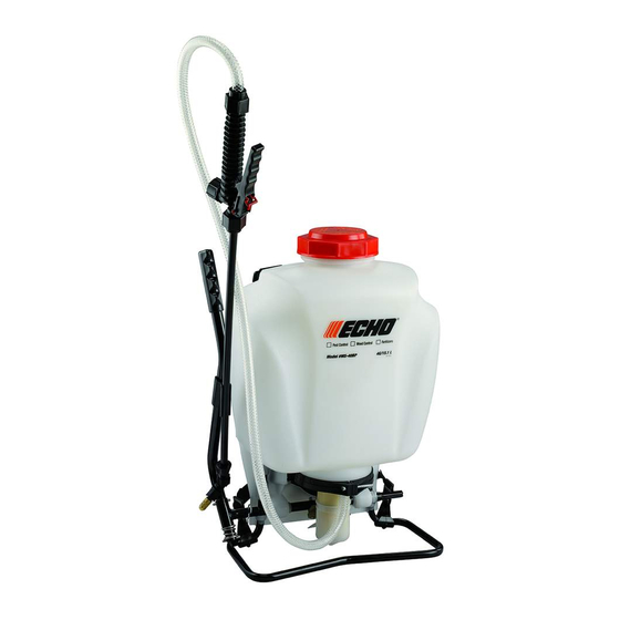
- Page 1 Backpack Use and Care Manual Model MS-40BP 4.0G/15.1L Carefully Read These Instructions Before Use WARNING! 011289 R0211...
-
Page 2: Rules For Safe Operation
IMPROPER USE OR FAILURE TO FOLLOW INSTRUCTIONS CAN RESULT IN PRODUCT FAILURE OR INJURIES. FOR SAFE USE OF THIS PRODUCT YOU MUST READ AND FOLLOW ALL INSTRUCTIONS BEFORE USING. WARNING: Handling the brass parts of this product will expose you to lead, a chemical known to the State of California to cause birth defects and other reproductive harm. -
Page 3: Wand Assembly
APPLICATIONS & USE FOR YOUR SPRAYER Avoid using a sprayer for general cleaning purposes if plant protection or herbicide chemicals have already been used in the sprayer. If a sprayer has been used for plant protection or as an herbicide, clean the sprayer completely (see cleaning section) before using. Plant Food: Use different spray patterns for optimum foliage feeding or for fungicide and pesticide application. -
Page 4: Installing The Shoulder Strap
SPRAYER COMPONENTS & USE INFORMATION, Continued INSTALLING THE PUMP HANDLE The pump handle can be mounted on either side of the pump shaft (A). To install the pump handle place the handle (C) over the shaft (A) aligning the pump handle hole and shaft hole. Push the straight side of the cotter pin (B) through the aligned hole as shown in figure 1 thru 3. -
Page 5: Filling The Sprayer
SPRAYER COMPONENTS & USE INFORMATION, Continued 4 STAGE FILTERING SYSTEM This backpack sprayer is equipped with a 4 stage filtering system (see figure 1). Stage 1 is a filter basket incorporated into the tank opening where fluid is added. Stage 2 and 3 filters are located at the inlet of the pressure cylinder. Stage 2 is a removable In-Tank filter. - Page 6 SPRAYER COMPONENTS & USE INFORMATION, Continued HELPFUL SPRAYING INFORMATION Use RAPID pump strokes to prime the pump. You will know the pressure chamber is filling with liquid when you feel firm resistance from the pump. The air in the pressure chamber is compressed from repeated strokes.
-
Page 7: Trouble Shooting Your Sprayer
STORING / MAINTAINING YOUR SPRAYER • The sprayer should be stored out of direct sunlight in a cool dry space. • Before freezing weather make sure to drain all liquid in the tank, pump, pressure cylinder, hose, shut-off valve, wand and nozzle, to avoid liquid expansion and cracking in the sprayer components (See “Cleaning”... - Page 8 DISASSEMBLING AND REPAIRING THE PISTON PUMP Figure 1 Figure 2 Figure 3 Collar Figure 4 Piston Cylinder Intake Upper Valve plate Lower Outlet Valve plate Passage Figure 5 Pressure cylinder base rib Piston cylinder tab Figure 6 1) Remove the cotter pin and pump handle. With the pump facing towards you, lay the unit on its back (Figure 1).
- Page 9 Figure 7 Figure 8 Protective Dust Cap Figure 9 DISASSEMBLING AND REPAIRING THE PUMP ASSEMBLY Only remove the pump assembly if the cartridge filter is clogged or the sprayer is leaking between the pressure chamber o-ring and tank. 1. Release the pressure from the sprayer and remove all liquid from both the pressure chamber and tank. 2.
- Page 10 8. At this point the filter cartridge in the pressure chamber base can be removed with pliers and cleaned (fig 4). 9. The pressure chamber o-ring can also be replaced. DO NOT stretch the o-ring over the bottom flange. Assemble the o-ring over the top of the Figure 4 chamber.
- Page 11 REPLACEMENT PARTS ORDER INFORMATION NOZZLE ASSEMBLY 99944100484 Flat Fan Nozzle O-ring Screw Hose Washer Retaining Nut Hose 99944100482 Brass Adjustable Nozzle 99944100485 Nozzle Kit Wand 99944100477 Shut-off Valve Repair Kit 99944100483 Poly Adjustable Nozzle 99944100481 Filter Replacement Kit 99944100480 Wand Assembly 99944100479 Hose...
- Page 12 Valve Plate - Piston Cylinder Piston Collar 99944100473 Filter Basket & Hose Gasket Wand O-ring 99944100472 Straps ECHO, INCORPORATED 400 Oakwood Road, Lake Zurich, IL 60047 www.echo-usa.com 99944100471 Piston Pump Repair Kit Collar- O-ring- Pump Piston Pressure Chamber O-ring- Piston Cylinder...
- Page 13 Instructions, as prescribed in the Use & Care Manual. Should a product difficulty occur, you must, at your expense, deliver or ship your ECHO unit to an authorized ECHO servicing dealer for warranty repairs (within the applicable warranty period), and arrange for pick-up or return of your unit after the repairs have been made.
Need help?
Do you have a question about the MS-40BP and is the answer not in the manual?
Questions and answers