
Related Manuals for Eagle 480


Summary of Contents for Eagle 480
- Page 1 Pub. 988-0143-711 www.eaglesonar.com FishMark 480 and SeaFinder 480DF Fish-finding & Depth Sounding Sonars Installation and Operation Instructions...
- Page 2 Eagle Electronics Marine-Tex is a trademark of Illinois Tool Works Inc. Eagle Electronics may find it necessary to change or end our policies, regulations, and special offers at any time. We reserve the right to do so without notice.
-
Page 3: Table Of Contents
Sec. 1: Read Me First! ... 1 Capabilities and Specifications ... 2 How Sonar Works ... 4 How to Use this Manual: Typographical Conventions... 4 Sec. 2: Installation & Accessories ... 7 Preparations... 7 Transducer Installation... 7 Recommended Tools and Supplies ... 8 Selecting a Transducer Location... - Page 4 Depth Alarms ... 46 Zone Alarm ... 47 Fish Alarm... 48 Brightness ... 48 Calibrate Speed... 49 Chart Speed... 49 Contrast... 50 Depth Cursor... 50 Depth Range - Automatic ... 51 Depth Range - Manual ... 51 FasTrack ... 52 Fish I.D....
- Page 5 Digital Data/Chart ... 72 Customizing the Digital Data/Chart Screen... 73 Sonar Simulator... 74 Stop Chart ... 74 Surface Clarity ... 75 Units of Measure... 76 Zoom & Zoom Bar ... 76 Zoom Pan... 77 Sec. 5: Troubleshooting... 79 Sec. 6: Supplemental Material... 83...
- Page 6 Notes...
-
Page 7: Section 1: Read Me First
First, we want to thank you for buying anEagle sonar. Whether you're a first time user or a professional fisherman, you'll discover that your unit is easy to use, yet capable of handling demanding sonar tasks. -
Page 8: Capabilities And Specifications
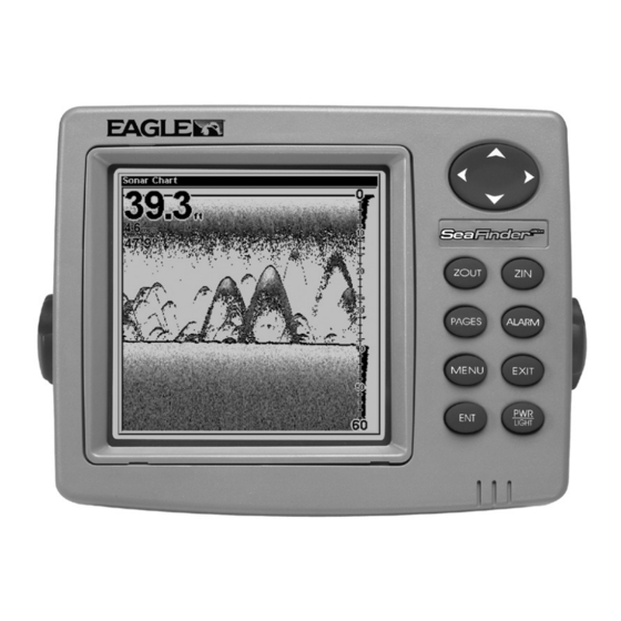
Capabilities and Specifications: FishMark 480, SeaFinder 480DF Display:... 5.0" (12.7 cm) diagonal high contrast Film Resolution:... 480 pixel x 480 pixel resolution; 230,400 total Backlighting:... Incandescent backlit screen with multiple Input power:... 10 to 15 volts DC. Case size:... 5.4" H x 6.9" W x 3.4" D (13.8 x 17.6 x 8.6 General SuperTwist;... - Page 9 SeaFinder 480DF. It has 35°/12° cone angles. A single-frequency Skimmer transducer with built-in temperature sensor is packed with the FishMark 480. It has a 20° cone angle. Transducers operate at speeds up to 70 mph (61 kts) FishMark 480: 800 feet (244 meters).
-
Page 10: How Sonar Works
Sonar has been around since the 1940s, so if you already know how it works, skip ahead to the next segment on the typographical conventions used in this manual. But, if you've never owned a sonar fish finder, this segment will tell you the under water basics. -
Page 11: Instructions = Menu Sequences
menu command to use by finding the boldface command text. The following paragraphs explain how to interpret the text formatting for those commands and other instructions: Arrow Keys The arrow keys control a horizontal line depth cursor on the sonar screen. - Page 12 Translated into complete English, step 1 above would mean: "Start on the Sonar Page. Press the Menu key then repeatedly press (or press and hold) the down arrow key to scroll down the menu and select (highlight) the Sonar Features menu command. Then press the Enter key." Step 2 would mean: "Press the right arrow key (for dual-frequency units) or press the right arrow key followed by the down arrow key (for single-frequency units) to select (highlight) the Fish ID symbols...
-
Page 13: Section 2: Installation & Accessories
Installation & Accessories Preparations You can install the sonar system in some other order if you prefer, but we recommend this installation sequence: Caution: You should read over this entire installation section before drilling any holes in your vessel! 1. Determine the approximate location for the sonar unit, so you can plan how and where to route the cables for the transducer and power. -
Page 14: Recommended Tools And Supplies
These are all "kick-up" mounting brackets. They help prevent damage if the transducer strikes an object while the boat is moving. If the transducer does "kick-up," the bracket can easily be pushed back into place without tools. Read these instructions carefully before attempting the installation. Determine which of the mounting positions is right for your boat. - Page 15 then the chosen location must be in the water at all times. If the transducer is not placed in a smooth flow of water, interference caused by bubbles and turbulence will show on the sonar's display in the form of random lines or dots whenever the boat is moving. NOTE: Some aluminum boats with strakes or ribs on the outside of the hull create large amounts of turbulence at high speed.
-
Page 16: How Low Should You Go
How low should you go? For most situations, you should install your Skimmer transducer so that its centerline is level with the bottom of the boat hull. This will usually give you the best combination of smooth water flow and protection from bangs and bumps. -
Page 17: Transom Transducer Assembly And Mounting
However, the shoot-thru-hull installation does have its drawbacks. First, some loss of sensitivity does occur, even on the best hulls. This varies from hull to hull, even from different installations on the same hull. This is caused by differences in hull lay-up and construction. Second, the transducer angle cannot be adjusted for the best fish arches. - Page 18 B. Two-piece bracket: Locate the four plastic ratchets in the transducer's hardware package. Press two ratchets into the sides of the plastic bracket and two on either side of the transducer as shown in the following illustrations. Notice there are letters molded into each ratchet. Place the ratchets into the bracket with the letter "A"...
- Page 19 2. Aligning the transducer on the transom. A. One-piece bracket: Slide the transducer between the two ratchets. Temporarily slide the bolt though the transducer assembly and hold it against the transom. Looking at the transducer from the side, check to see if it will adjust so that its face is parallel to the ground.
- Page 20 bracket holes with the letter "B" aligned with the bracket alignment mark. Place them on the transducer aligned with the 12 o'clock position on the transducer stem. Reassemble the transducer and bracket and place them against the transom. Again, check to see if you can move the transducer so it's parallel with the ground.
- Page 21 B. Two-piece bracket: Once you determine the correct position for the ratchets, assemble the transducer as shown in the figure in step 2B. Don't tighten the lock nut at this time. 4. Drilling mounting holes. Hold the transducer and bracket assembly against the transom. The transducer should be roughly parallel to the ground.
- Page 22 Both bracket types: Attach the transducer to the transom. Slide the transducer up or down until it's aligned properly with the bottom of the hull as shown in the preceding and following figures. Tighten the bracket's mounting screws, sealing them with the caulking compound. Adjust the transducer so that it's parallel to the ground and tighten the nut until it touches the outer washer, then add 1/4 turn.
-
Page 23: Trolling Motor Bracket Installation (Single-Frequency Only)
Caution: If you drill a hole in the transom for the cable, make sure it is located above the waterline. After installation, be sure to seal the hole with the same marine grade above- or below-waterline sealant used for the mounting screws. 7. -
Page 24: Transducer Orientation And Fish Arches
Transducer mounted on trolling motor, side view. TRANSDUCER ORIENTATION AND FISH ARCHES If you do not get good fish arches on your display, it could be because the transducer is not parallel with the ground when the boat is at rest in the water or at slow trolling speeds. -
Page 25: Shoot-Thru-Hull Preparation And Installation
If the arch slopes up – but not back down – then the front of the transducer is too high and needs to be lowered. If only the back half of the arch is printed, then the nose of the transducer is angled too far down and needs to be raised. - Page 26 WARNING: Do not remove any material from your inner hull unless you know the hull's composition. Careless grinding or cutting on your hull can result in damage that could sink your manufacturer to confirm your hull specifications. To choose the proper location for thru-hull mounting, anchor the boat in 60 feet of water.
-
Page 27: Speed/Temperature Sensors
This unit is packed with a transducer containing a built-in temp sensor. The SeaFinder package also includes a speed sensor. If you have a FishMark 480 and want a speed sensor or additional temp sensor, see the Accessory Ordering Information in the back of this manual. - Page 28 If a second temp sensor is used, it must be the model TS-2U. This model has a fixed electronic "address" which designates it as the second of two temp sensors. Dual temperatures are only displayed on the Full Chart page. The Large Digital page will only display the primary temperature sensor.
- Page 29 Optional Speed Sensor Installation All the units in this series can display speed and distance traveled, but only the SeaFinder 480DF comes packed with a speed sensor. If you wish to purchase an optional additional sensor for your unit, refer to the accessory ordering information inside the back cover of this manual.
-
Page 30: Power Connections
Good location Stern view showing good location for mounting sensor on transom. If the base of the transom has a radius, fill the gap between the transom and the sensor with the caulking compound. This will help ensure a smooth water flow. Transom Speed sensor mounting configuration: side view (left) and rear view (right.) - Page 31 attach the power cable directly to the battery. You can attach the power cable to an accessory or power buss, however you may have problems with electrical interference. Therefore, it's safer to go ahead and attach the power cable directly to the battery. CAUTION: When using the unit in a saltwater environment, we strongly recommend that you shut off the power supply to the power cable...
-
Page 32: Mounting The Unit: Bracket, In-Dash Or Portable
This unit has reverse polarity protection. No damage will occur if the power wires are reversed. However, the unit will not work until the wires are attached correctly. An optional 8-foot, CA-4 external power cable with a cigarette lighter adapter is available from Eagle. Sonar unit rear view Power/trans-... - Page 33 If you use the supplied bracket, you may be interested in the optional R-A-M bracket mounting system. This converts the unit's gimbal bracket to a swivel mount, which can be used on the dash or overhead mounting positions. Installation instructions are supplied with the R-A-M mounting kits.
- Page 34 After drilling the hole, pass the transducer connector up through the hole from under the dash. Pass the power cable's bare-wire end down though the hole from the top. If you wish, you can fill in the hole around the cables with a good marine caulking compound.
- Page 35 Portable Installation Like many Eagle products, this sonar unit is capable of portable operation by using the optional PPP-13 portable power pack. The power pack and an optional portable transducer expand the uses for your sonar unit.
-
Page 36: Face Cover
The PPP-13 Portable Power Pack can be used with eight "D" cell alkaline batteries or an optional sealed, rechargeable battery. For set- up directions, refer to the pack's instruction sheet, part 988-0147-601. "D" cell battery Install batteries in power pack battery adapter. Face Cover Your unit comes with a white protective cover that snaps on and off the front of the unit. -
Page 37: Section 3: Basic Sonar Operation
Section 3: Basic Sonar Operation This section addresses the unit's most basic sonar operations. The instructions presented here in Sec. 3 follow a chronological order. Sec. 4, Sonar Options & Other Features, will discuss options and other more advanced functions and utilities. The material in Sec. 4 is arranged in alphabetical order. -
Page 38: Power/Lights (Turn Unit On And Off)
1. PWR/LIGHT (Power & Light) – The PWR key turns the unit on and off and activates the backlight. 2. PAGES – Pressing this and the ↑ ↓ arrow keys switches the unit between the four different page options. (Full Sonar Chart, Split Zoom Sonar Chart, Split Frequency Sonar Chart and Digital Data.) 3. -
Page 39: Menus
Menus Your sonar unit will work fine right out of the box with the factory default settings. You only need to learn a few basic functions to enhance your viewing. We'll discuss them briefly here, then talk about them and all the other commands in more detail in the next section, which begins on page 45. - Page 40 Main Menu Commands There are four "basic" Main Menu commands that you'll really want to read more about. They are: • Screen command: changes the contrast or brightness of the display screen. Use this command to adjust how the screen looks under various lighting conditions.
-
Page 41: Sonar Menu
• Reset Options command: returns all options and auto functions to their original factory settings. It's a great safety net while you're learning and experimenting with various settings. • Set Language command: your unit has menus in 10 different languages. This command switches from one language to another. •... - Page 42 Sensitivity and Auto Sensitivity are important basic functions that are discussed both here and in Sec. 4. The other Sonar Menu commands include: • Grayline command: separates fish and structure near the bottom from the actual bottom, and defines bottom composition/hardness. •...
- Page 43 Pages Menu showing some Sonar display options (at left, dual-frequency menu; at right, single-frequency menu). The Full Sonar Chart is the main display option. This is a "cross- section" view of the water column beneath the boat. The chart moves across the screen, displaying sonar signal echoes that represent fish, structure and the bottom.
- Page 44 Sonar chart display options (from left) split zoom (all models) and split frequency (SeaFinder 320DF only). Digital data sonar chart display option. You can customize how the Sonar Page pictures and other data are displayed in many ways. We'll discuss all of those features and options in Section 4, but to show you how easy the sonar unit is to operate, see the following 10-step quick reference that will cover most fish finding situations.
-
Page 45: Basic Sonar Quick Reference
Basic Sonar Quick Reference 1. Mount the transducer and unit. Connect the unit to electric power and the transducer. 2. Launch your boat. 3. To turn on the unit, press and release 4. Head for your fishing grounds. Your unit automatically displays digital depth and surface water temperature in the corner of the screen. -
Page 46: Sonar Operations
9. If you are drifting at a very low speed or anchored, you are not moving fast enough for a fish to return the tell-tale fish arch signal. As you drift over a fish, or as a fish swims through the transducer's signal cone, the fish echo will appear as a straight line suspended between the surface and the bottom. - Page 47 Adjusting sensitivity in Manual Sensitivity Mode is similar to driving a car without cruise control — you have complete manual control of the car's speed. In the sonar unit, manual mode allows you to set sensitivity at 100 percent (maximum) or zero percent (minimum.) Depending on water conditions, the bottom signal may completely disappear from the screen when you reduce sensitivity to about 50 percent or less!
- Page 48 To adjust sensitivity: 1. Press MENU 2. The Sensitivity Control Bar appears. Press ↓ to decrease sensitivity; press ↑ to increase sensitivity. When it's set at the desired level, press . (When you reach the maximum or minimum limit, a tone sounds.) EXIT At left, Sonar Menu with Sensitivity command selected.
-
Page 49: Fish Symbols Vs. Full Sonar Chart
Fish Symbols vs. Full Sonar Chart You may have noticed in the quick reference that we used fish arches in full sonar chart mode for our example, and not the popular Fish I.D. fish symbol feature. Here's why. Fish I.D. is an easier way for a sonar novice to recognize a fishy signal return when he sees it. - Page 50 Aside from being just plain fun, this program can help you learn both basic and advanced operations without burning boat fuel! Eagle is one of the first sonar manufacturers to provide this type of training tool for customers.
-
Page 51: Section 4: Sonar Options & Other Features
Section 4: Sonar Options & Other Features Material in this section is arranged in alphabetical order. ASP (Advanced Signal Processing) The ASP feature is a noise rejection system built into the sonar unit that constantly evaluates the effects of boat speed, water conditions and interference. -
Page 52: Alarms
To change the ASP level: 1. From the Sonar Page, press 2. Press → ↓ or ↓ to 3. Press ↓ or ↑ to select a setting, then press 4. To return to the previous page, press Alarms The last alarm is the Depth Alarm, which has both a Shallow and a Deep setting. -
Page 53: Zone Alarm
To adjust and turn on the shallow alarm: 1. Press LARM 2. Press → to HALLOW 3. Press ↑ or ↓ to change the first number, then press → to move the cursor to the next number and repeat until the depth is correct, then press 4. -
Page 54: Fish Alarm
Adjust Zone Alarm selection box, with Upper selected. 3. To set the upper boundary for the Zone Alarm, use ← or→ to select , then press ↑ or ↓ to move the top of the bar to the desired depth. PPER 4. -
Page 55: Calibrate Speed
Calibrate Speed The speed sensor can be calibrated to compensate for inaccuracies. Before you change the setting, first calculate the percentage that the speed is off. You will enter this percentage in a moment. For example, if you figure the sensor is reading 10 percent faster than actual speed, you will enter –... -
Page 56: Contrast
If you do experiment with chart speed, remember to reset it to maximum when you resume trolling or moving across the water at higher speed. To change chart speed: 1. From the Sonar Page, press |↓ to MENU HART PEED 2. -
Page 57: Depth Range - Automatic
1. From the Sonar Page, press 2. The depth cursor appears. Press ↓ to lower the cursor line; press ↑ to raise the cursor line. 3. To clear the depth cursor, press Depth Range - Automatic When turned on for the first time, the bottom signal is automatically placed in the lower half of the screen. -
Page 58: Fastrack
To turn Auto Depth Range on again: 1. From the Sonar Page, press NOTE: sonar's installation, water and bottom conditions, and other factors. FasTrack This feature automatically converts all echoes to short horizontal lines on the display's far right side. The graph on the rest of the screen continues to operate normally. - Page 59 There are several fish symbol sizes. These are used to designate the relative size between targets. In other words, Fish I.D. displays a small fish symbol when it thinks a target is a small fish, a medium fish symbol on a larger target and so on. The sonar's microcomputer is sophisticated, but it can be fooled.
- Page 60 Fig. 1 A Fig. 1 B Many fish Fewer fish arches visible symbols visible Fig. 2 A Fig. 2 B Fish arches No fish shown above structure FasTrack graph confirms fish above structure At left, figures 1A and 2A show Sonar Page in normal chart mode. At right, figures 1B and 2B show the same underwater scene with Fish I.D.
-
Page 61: Fishtrack
FishTrack The FishTrack feature shows the depth of a fish symbol when it appears on the display. This lets you accurately gauge the depth of targets. This feature is available only when the Fish I.D. feature is on. The default setting for FishTrack is off. To turn on FishTrack: (Note: These instructions will turn on FishTrack and Fish I.D. - Page 62 The normal mode of operation (with FishReveal turned off) shows the weakest echoes as black and the strongest echoes in light gray. Since all weak echoes are black, fish arches show boldly against the white background. The drawback is that all weak echoes – such as thermoclines –...
-
Page 63: Frequency (Change Transducer Frequency)
Fish visible Fish arch Sonar chart in regular grayscale mode, left, and in FishReveal mode, right. Notice how shallow fish formerly hidden in the surface clutter become visible in FishReveal mode. NOTE: Water conditions vary greatly, and that affects sonar performance. Under certain conditions, FishReveal will show you more fish than normal grayscale mode, but the reverse will be true in other circumstances. -
Page 64: Grayline
all sonar units typically read deeper in fresh water than in salt water.) There is a common exception to these rules of thumb. Some fishermen on freshwater lakes (or the ocean) using downriggers like to see them on the sonar. In many of those cases, you'll see a 50 kHz transducer frequency in use because the wider cone angle lets them watch the bait. - Page 65 Grayline is adjustable. Experiment with your unit to find the Grayline setting that's best for you. To adjust the Grayline level: 1. From the Sonar Page, press 2. The Grayline Control Bar appears. Press ↓ to decrease Grayline; press ↑ to increase Grayline. 3.
-
Page 66: Hyperscroll
Fig. 3A Fig. 3B Hard Muddy bottom bottom Grayline This series of figures shows how different Grayline settings can reveal more information. The "A" figures to the left show locations with Grayline set at the factory level of 64 percent. At right, the "B" figures show the same locations with Grayline increased to 84 percent. - Page 67 At left, we scrolled down the data list to highlight "Water Speed." At right, data list showing "Water Speed" selected to display on Sonar Page. 3. To return to the previous page, press To turn off displayed data: 1. Press |↓...
-
Page 68: Ping Speed & Hyperscroll
1. Press |↓ to MENU 2. Press ↓ or ↑ to select Data Type|press → or ← to select Size The data will be shown in the new font size. To return to the previous page, press NOTE: Some data types can be displayed in only one font size. If that is the case, the Data Size box will not be displayed for that data type. - Page 69 These faster ping rates allow you to maintain a high-detail picture on the screen, and the screen refresh rate and chart scroll speed can keep pace with the boat as it moves quickly over the bottom terrain. When using HyperScroll, you may also need to manually decrease the sensitivity for optimum performance.
-
Page 70: Pop-Up Help
Pop-up Help Help is available for virtually all of the menu labels on this unit. By highlighting a menu item and leaving it highlighted for a few seconds, a "pop-up" message appears that describes the function of the menu item. This feature is on by default. -
Page 71: Reset Water Distance
Reset Water Distance The sonar chart's Digital Data display option includes a window that shows distance traveled, called Water Distance ("W Distance"). This information is calculated from an optional water speed sensor. The Water Distance window can be reset to zero using the Reset Water Distance command. - Page 72 best sensitivity level shows a good solid bottom signal with Grayline and some surface clutter. Automatic Sensitivity The default sensitivity mode is automatic. The unit bases the sensitivity level on water depth and conditions. When the unit is in the automatic mode, sensitivity is automatically adjusted to keep a solid bottom signal displayed, plus a little more power.
-
Page 73: To Turn Auto Sensitivity Back On
To adjust sensitivity in manual mode: 1. First, turn off Auto Sensitivity: from the Sonar Page, press ENSITIVITY 2. Press ↑ to ENSITIVITY Press ↓ or ↑ to pick a different sensitivity setting. When it's set at the desired level, press To turn Auto Sensitivity back on: 1. - Page 74 feature eliminates the need for the navigator to mentally calculate how much water is under his keel. Keel Offset lets you calibrate the digital depth: chart depth scale, chart cursor depth and fish symbol depth displayed on the screen. To calibrate the depth indicators, first measure the distance from the face of the transducer to the lowest part of the boat.
-
Page 75: Set Language
Software Version Information From time to time, Eagle updates the operating system software in some of its products. These software upgrades are usually offered to customers as free downloads from our web site, www.eaglesonar.com. -
Page 76: Sonar Chart Display Options
2. Press ↓ to ONAR OLOR 3. Press ↓ or ↑ to Mode Name 4. Press to return to the Sonar Page. EXIT EXIT Sonar Chart Display Options The Pages Menu offers four chart display options for dual-frequency models and three options for single-frequency models. To access them, press |↓... -
Page 77: Split Zoom Sonar Chart
Full Sonar Chart. The Overlay Data (depth and water temperature) are both set to the small text size. Split Zoom Sonar Chart A split chart shows the underwater world from the surface to the bottom on the right side of the screen. The left side shows an enlarged version of the right side. -
Page 78: Digital Data/Chart
Split Frequency Sonar Chart page, with 50 kHz view at left and 200 kHz view at right. You can adjust the sensitivity in each window. To adjust sensitivity in auto mode: 1. Press MENU 2. The unit asks which you wish to adjust. Press ← or→ to select the one you want | 3. -
Page 79: Customizing The Digital Data/Chart Screen
and Voltage used. (Note: Temperature #2 requires an additional optional temperature sensor.) Customizing the Digital Data/Chart Screen The Digital Data/Chart screen can be customized to show digital data different from the defaults first shown. To customize this screen: 1. From the Sonar Page (in Digital Data mode), press USTOMIZE 2. -
Page 80: Sonar Simulator
Data Type and pressing Enter, use the ↓ key to select another window to change. When the selected window title bar flashes, |↑ or ↓ to select data type| press you're finished customizing, then press Page. Sonar Simulator This unit has a built-in simulator that lets you run it as if you were on the water. -
Page 81: Surface Clarity
Surface Clarity The markings extending downward from the zero line on the chart are called "surface clutter." These markings are caused by wave action, boat wakes, temperature inversion and more. The surface clarity control reduces or eliminates surface clutter signals from the display. -
Page 82: Units Of Measure
Surface clutter In the illustration at left, Surface Clarity is turned off. The right view shows Surface Clarity set at High. Units of Measure To set Speed/Distance Unit of Measure: Speed/Distance, then to return to the page display. EXIT|EXIT|EXIT Zoom & Zoom Bar "Zooming"... -
Page 83: Zoom Pan
Pressing once doubles the size (2X) of all echoes on the screen. Pressing it again quadruples the size of the echoes (4X). The zoom bar on the far right side of the screen shows which echoes will be displayed on the screen when the key is pressed. - Page 84 Notes...
-
Page 85: Section 5: Troubleshooting
Section 5: Troubleshooting If your unit is not working, or if you need technical help, please use the following troubleshooting section before contacting the factory customer service department. It may save you the trouble of returning your unit for repair. For contact information, refer to the last page, just inside the back cover of this manual. - Page 86 Weak bottom echo, digital readings erratic, or no fish signals: 1. Make certain the transducer is pointing straight down. Clean the face of the transducer. Oil, dirt and fuel can cause a film to form on the transducer, reducing its effectiveness. If the transducer is mounted inside the hull, be sure it is shooting through only one layer of fiberglass and that it is securely bonded to the hull.
- Page 87 spark plugs or routing the sonar unit's power and transducer cables away from other electrical wiring on the boat. No fish arches when the Fish I.D. feature is off: 1. Make certain the transducer is pointing straight down. This is the most common problem if a partial arch is displayed.
- Page 88 no noise is present, turn the pump off, then turn on the VHF radio and transmit. Keep doing this until all electrical equipment has been turned on, their effect on the sonar display noted, then turned off. If you find noise interference from an electrical instrument, trolling motor, pump, or radio, try to isolate the problem.
-
Page 89: Section 6: Supplemental Material Fcc Compliance
Section 6: Supplemental Material This device complies with Part 15 of the U.S. Federal Communications Commission (FCC) Rules. Operation is subject to the following two conditions: (1) this device may not cause harmful interference, and (2) this device must accept any interference received, including interference that may cause undesired operation. - Page 90 Notes...
- Page 91 THIS IS A LEGAL AGREEMENT BETWEEN THE END-USER WHO FIRST PURCHASES THIS PRODUCT AS A CONSUMER ITEM FOR PERSONAL, FAMILY, OR HOUSEHOLD USE ("YOU") AND EAGLE ELECTRONICS, A DIVISION OF LEI, THE MANUFACTURER OF THIS PRODUCT ("WE", "OUR", OR "US"). USING THE PRODUCT ACCOMPANIED BY THIS LICENSE AGREEMENT CONSTITUTES ACCEPTANCE OF THESE TERMS AND CONDITIONS.
-
Page 92: Databases Limited Warranty
DATABASES LIMITED WARRANTY "We", "our", or "us" refers to Eagle Electronics, a division of LEI, the manufacturer of this product. "You" or "your" refers to the first person who purchases the product as a consumer item for personal, family, or household use. The Databases Limited Warranty applies to the one or more databases that your product may contain. - Page 93 EAGLE ELECTRONICS FULL ONE-YEAR WARRANTY "We," "our," or "us" refers to EAGLE ELECTRONICS, a division of LEI, the manufacturer of this product. "You" or "your" refers to the first person who purchases this product as a consumer item for personal, family, or household use.
-
Page 94: How To Obtain Service
8 a.m. to 5 p.m. Central Standard Time, M-F Eagle Electronics may find it necessary to change or end our shipping policies, regulations, and special offers at any time. We reserve the right to do so without notice. -
Page 95: Accessory Ordering Information For All Countries
1. Always use the original shipping container and filler material the product was packed in. 2. Always insure the parcel against damage or loss during shipment. Eagle does not assume responsibility for goods lost or damaged in transit. 3. For proper testing, include a brief note with the product describing the problem. -
Page 96: Visit Our Website
Eagle Pub. 988-0143-711 Printed in USA 103103 Visit our web site: www.eaglesonar.com © Copyright 2003 All Rights Reserved Eagle Electronics...
Need help?
Do you have a question about the 480 and is the answer not in the manual?
Questions and answers