Table of Contents
Advertisement
Quick Links
Advertisement
Table of Contents

Related Manuals for Asus Maximus V Extreme


Summary of Contents for Asus Maximus V Extreme
- Page 1 MAXIMUS V EXTREME...
- Page 2 Product warranty or service will not be extended if: (1) the product is repaired, modified or altered, unless such repair, modification of alteration is authorized in writing by ASUS; or (2) the serial number of the product is defaced or missing.
-
Page 3: Table Of Contents
Product Introduction Special features..................1-1 1.1.1 Product highlights................ 1-1 1.1.2 ROG Intelligent Performance & Overclocking features ....1-2 1.1.3 ASUS special features ..............1-4 1.1.4 ROG-rich bundled software............1-4 Motherboard overview ................1-6 1.2.1 Before you proceed ..............1-6 1.2.2 Motherboard layout .............. - Page 4 3.5.9 Network Stack ................3-36 Monitor menu ................... 3-37 Boot menu ....................3-41 Tools menu ....................3-43 3.8.1 ASUS EZ Flash 2 Utility ............3-43 3.8.2 ASUS O.C. Profile ..............3-43 3.8.3 ASUS SPD Information ............. 3-44 3.8.4 GO Button File ................3-45 Exit menu ....................
- Page 5 4.3.8 Ai Charger+ ................4-34 4.3.9 USB Charger+ ................4-35 4.3.10 Probe II..................4-37 4.3.11 Sensor Recorder ............... 4-38 4.3.12 ASUS Update ................4-40 4.3.13 MyLogo2 ................... 4-41 4.3.14 Audio configurations..............4-42 4.3.15 ROG Connect................4-44 4.3.16 MemTweakIt ................4-46...
- Page 6 2012 Desktop responsiveness technologies ......... 7-1 ® 7.1.1 Intel Smart Response Technology ..........7-3 ® 7.1.2 Intel Rapid Start Technology ............7-4 ® 7.1.3 Intel Smart Connect Technology ..........7-10 ® Appendices Notices ........................A-1 ASUS contact information ..................A-5...
-
Page 7: Safety Information
Safety information Electrical safety • To prevent electrical shock hazard, disconnect the power cable from the electrical outlet before relocating the system. • When adding or removing devices to or from the system, ensure that the power cables for the devices are unplugged before the signal cables are connected. If possible, disconnect all power cables from the existing system before you add a device. -
Page 8: About This Guide
Refer to the following sources for additional information and for product and software updates. ASUS websites The ASUS website provides updated information on ASUS hardware and software products. Refer to the ASUS contact information. Optional documentation Your product package may include optional documentation, such as warranty flyers, that may have been added by your dealer. -
Page 9: Conventions Used In This Guide
Conventions used in this guide To ensure that you perform certain tasks properly, take note of the following symbols used throughout this manual. DANGER/WARNING: Information to prevent injury to yourself when trying to complete a task. CAUTION: Information to prevent damage to the components when trying to complete a task IMPORTANT: Instructions that you MUST follow to complete a task. -
Page 10: Maximus V Extreme Specifications Summary
Turbo Boost Technology 2.0 ® * The Intel Turbo Boost Technology 2.0 support depends on the CPU ® types. ** Refer to www.asus.com for Intel CPU support list Chipset Intel Z77 Express Chipset ® Memory 4 x DIMM, max. 32GB, DDR3 2800 (O.C.) / 2666(O.C.) / 2600(O.C.) / 2400 (O.C.) / 2200(O.C.) / 2133(O.C.) /... - Page 11 MAXIMUS V EXTREME specifications summary Intel Z77 Express Chipset with RAID 0, 1, 5, 10 support Storage ® - 2 x SATA 6.0 Gb/s ports [red] - 3 x SATA 3.0 Gb/s ports [black]; 1 port at mid-board reserved for eSATA*** - 1 x mSATA 3.0 Gb/s slot on mPCIe Combo™...
- Page 12 - USB 3.0 Boost - Fan Xpert2 - AI Charger+ - USB Charger+ - Disk Unlocker ASUS EZ DIY - ASUS CrashFree BIOS 3 - ASUS EZ Flash 2 - ASUS C.P.R. (CPU Parameter Recall) (continued on the next page)
- Page 13 Special Features ASUS Q-Design - ASUS Q-Code - ASUS Q-Shield - ASUS Q-Connector - ASUS Q-LED (CPU, DRAM, VGA, Boot Device LED) - ASUS Q-Slot - ASUS Q-DIMM Back I/O Ports 1 x Thunderbolt port 1 x Clear CMOS button 1 x ROG Connect On/Off button 4 x USB 2.0 (1 port for ROG Connect)
- Page 14 Software Drivers Kaspersky Anti-Virus ® DAEMON Tools Pro Standard ROG CPU-Z Mem TweakIt ASUS AI Suite II ASUS WebStorage ASUS Utilities Form Factor Extended ATX Form Factor, 12” x 10.7” (30.5cm x 27.2cm) Specifications are subject to change without notice.
-
Page 15: Package Contents
1 x mPCIe Combo card with dual band Wi-Fi / Bluetooth module 2 x dual band Wi-Fi Ring Moving Antenna 1 x 2-port USB 2.0 and eSATA module 1 x 12-in-1 ROG cable label 1 x 2-in-1 ASUS Q-Connector kit Application DVD ROG motherboard support DVD Documentation User guide... -
Page 16: Installation Tools And Components
Installation tools and components 1 bag of screws Philips (cross) screwdriver PC chassis Power supply unit Intel LGA 1155 CPU Intel LGA 1155 compatible CPU Fan DDR3 DIMM SATA hard disk drive SATA optical disc drive (optional) Graphics card (optional) The tools and components in the table above are not included in the motherboard package. -
Page 17: Chapter 1: Product Introduction
This motherboard features a unique PCIe 3.0 bridge chip to support multi-GPU SLI/ CrossFireX graphics cards for an unrivaled gaming performance. With the Intel Z77 platform to optimize the PCIe allocation of multiple GPUs, it supports up to 4-WAY GPU SLI or 4-WAY GPU CrossFireX configuration. ASUS MAXIMUS V EXTREME... -
Page 18: Rog Intelligent Performance & Overclocking Features
LucidLogix Virtu™ MVP ® LucidLogix Virtu™ MVP, with HyperFormance™ Technology, is designed for Intel processor ® ® graphics chip on Windows 7 and perfectly combines the performance of a discrete graphics ® card with fast computing iGPU (Integrated Graphics Processing Unit). The newly-designed Virtual VSync eliminates tearing artifacts allowing you to enjoy a smoother gaming experience. -
Page 19: Usb Bios Flashback
BIOS for the tweaked overclocking setting, and one saved BIOS from the previous version. VGA Hotwire Using the VGA Hotwire feature, you can plug two-wired cable onboard and solder two wires on the VGA’s voltage regulator to adjust the voltages accurately without risk. ASUS MAXIMUS V EXTREME... -
Page 20: Asus Special Features
ASUS special features Wi-Fi GO! ASUS Wi-Fi GO! leads the way to a more enjoyable home entertainment. With ASUS Wi-Fi GO!, you can wirelessly stream media files to DLNA devices, remotely control and access your computer using your mobile device, and easily transfer files between your computer and mobile device. - Page 21 Get that ROG look of reporting your system’s current information with ROG CPU-Z. MemTweakIt MemTweakIt is a DRAM efficiency tool that allows you to fine-tune your DRAM in real time and allows you to post and share your DRAM configuration scores to the ROG website. ASUS MAXIMUS V EXTREME...
-
Page 22: Motherboard Overview
Motherboard overview 1.2.1 Before you proceed Take note of the following precautions before you install motherboard components or change any motherboard settings. • Unplug the power cord from the wall socket before touching any component. • Before handling components, use a grounded wrist strap or touch a safely grounded object or a metal object, such as the power supply case, to avoid damaging them due to static electricity. -
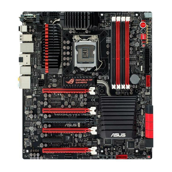
Page 23: Motherboard Layout
1.2.2 Motherboard layout Refer to 1.2.9 Internal connectors and 2.3.1 Rear I/O connection for more information about rear panel connectors and internal connectors. ASUS MAXIMUS V EXTREME... -
Page 24: Layout Contents
Layout contents Connectors/Jumpers/Buttons and switches/Slots Page 1. Power connectors (24-pin EATXPWR, 8-pin EATX12V, 4-pin EATX12V) 1-48 2. LGA1155 CPU Socket 3. CPU, chassis, and optional fan connectors (4-pin CPU_FAN, 4-pin 1-46 CPU_OPT, 4-pin OPT_FAN1-3, 4-pin CHA_FAN1-3) 4. DDR3 DIMM slots 1-10 5. -
Page 25: Central Processing Unit (Cpu)
Contact your retailer immediately if the PnP cap is missing, or if you see any damage to the PnP cap/socket contacts/motherboard components. ASUS will shoulder the cost of repair only if the damage is shipment/ transit-related. -
Page 26: System Memory
1.2.4 System memory The motherboard comes with four Double Data Rate 3 (DDR3) Dual Inline Memory Modules (DIMM) slots. A DDR3 module is notched differently from a DDR or DDR2 module. DO NOT install a DDR or DDR2 memory module to the DDR3 slot. Recommended memory configurations Chapter 1: Product introduction 1-10... -
Page 27: Memory Configurations
3.3 Extreme Tweaker menu for manual memory frequency adjustment. • For system stability, use a more efficient memory cooling system to support a full memory load (4 DIMMs) or overclocking condition. ASUS MAXIMUS V EXTREME 1-11... - Page 28 MAXIMUS V EXTREME Motherboard Qualified Vendors Lists (QVL) DDR3 2800 MHz capability Vendors Part No. Size Chip Chip Timing Voltage DIMM socket Brand support (Optional) G.skill F3-2800CL11Q-16GBZHD 16GB 11-13- 1.65 • • (4x4GB) 13-35 DDR3 2666 MHz capability Vendors Part No. Size Chip Chip...
- Page 29 1.65 • (XMP) (4x4GB) 9-27 Apacer 78.BAGE4.AFD0C (XMP) 9-9-9- • • • (2x4GB) CORSAIR CMT4GX3M2A213 9-10- 1.65 • • 3C9(XMP) (2x2GB) 9-24 CORSAIR CMT4GX3M2B2133 9-9-9- • • • C9(Ver7.1)(XMP) (2x2GB) (continued on the next page) ASUS MAXIMUS V EXTREME 1-13...
- Page 30 DDR3 2133 MHz capability Vendors Part No. Size Chip Brand Chip Timing Voltage DIMM socket support (Optional) CORSAIR CMT4GX3M2B2133 9-10- • • • C9(XMP) (2x2GB) 9-27 G.SKILL F3-17000CL11Q2-64 64GB 11-11- • • • GBZLD(XMP) (8x8GB) 11-30 G.SKILL F3-17000CL9Q-16G 16GB 9-11- 1.65 •...
- Page 31 • (Ver3.23)(XMP) (4x8GB) 9-27 CORSAIR CMZ16GX3M4X1866C9R 16GB 9-9-9- • • • (Ver8.16)(XMP) (4x4GB) CORSAIR CMZ32GX3M4X1866C10 32GB 10-11- • • • (Ver3.23)(XMP) (4x8GB) 10-27 CORSAIR CMZ8GX3M2A1866C9(XMP) 9-10- • • (2x4GB) 9-27 (continued on the next page) ASUS MAXIMUS V EXTREME 1-15...
- Page 32 DDR3 1866 MHz capability Vendors Part No. Size Chip Chip NO. Timing Voltage DIMM socket support Brand (Optional) Crucial BLE4G3D1869DE1XT0.16 9-9-9- • • • FMD(XMP) G.SKILL F3-14900CL10Q2-64GBZ 64GB 10-11- • • • LD(XMP) (8x8GB) 10-30 G.SKILL F3-14900CL9D-8GBSR(XMP) 9-10- • • •...
- Page 33 • • 9(XMP) (2x4GB) CORSAIR CMZ8GX3M4X1600C 9-9-9-24 • • • 9(Ver 2.12)(XMP) (4x2GB) CORSAIR HX3X12G1600C9(XMP) 12GB 9-9-9-24 • • • (6x2GB) Crucial BL12864BN1608.8F 8-8-8-24 1.65 • • • F(XMP) (2x1GB) (continued on the next page) ASUS MAXIMUS V EXTREME 1-17...
- Page 34 DDR3 1600 MHZ Capability Vendors Part No. Size Chip Chip Timing Voltage DIMM socket support Brand (Optional) Crucial BLT4G3D1608DT1TX 8-8-8-24 • • • 0.16FM(XMP) EK Memory EKM324L28BP8-I16 • • • (XMP) (2x2GB) EK Memory EKM324L28BP8-I16 • • • (XMP) (2x2GB) Elixir M2X2G64CB88G7N- Elixir...
- Page 35 3BFRPBC SanMax SMD-4G68NG-16KK ELPIDA J2108B • • • DBG-GN-F Silicon SP002GBLTU160V S-POWER 20YT5NG 9-11- • • • Power 02(XMP) 11-28 Silicon SP004GBLTU160V0 S-POWER 20YT5NG 9-9-9-24 • • • Power 2(XMP) (continued on the next page) ASUS MAXIMUS V EXTREME 1-19...
- Page 36 DDR3 1600 MHz capability Vendors Part No. Size Chip Chip NO. Timing Voltage DIMM socket Brand support (Optional) Team TED34096M1600HC11 Team T3D2568ET-16 • • • Team TXD31024M1600C8- Team T3D1288RT-16 8-8-8- 1.65 • • • D(XMP) Team TXD32048M1600C7- Team T3D1288LT-16 7-7-7- 1.65 •...
- Page 37 9-9-9-24 • • • (2x2GB) 88BA15B GEIL GVP34GB1333 9-9-9-24 • • • C9DC (2x2GB) GEIL GVP38GB1333 7-7-7-24 • • • C7QC (4x2GB) GEIL GVP38GB1333 9-9-9-24 • • • C9DC (2x4GB) (continued on the next page) ASUS MAXIMUS V EXTREME 1-21...
- Page 38 DDR 1333 MHz capability Vendors Part No. Size Chip Brand Chip NO. Timing Voltage DIMM socket support (Optional) GoodRam GR1333D364L9/2G Qimonda IDSH1G- • • • 03A1F1C-13H Hynix HMT125U6TFR8A- Hynix H5TC1 • • • G83TFR INNODISK M3UN-2GHJBC09 Hynix H5TQ2G83 9-9-9- • •...
- Page 39 • • • C7(XMP) Team TXD31048M1333 Team T3D1288LT-13 7-7-7-21 1.75 • • C7-D(XMP) Team TXD32048M1333 Team T3D1288LT-13 7-7-7-21 1.5-1.6 • • • C7-D(XMP) Transcend JM1333KLN-2G Transcend TK483PCW3 • • • (continued on the next page) ASUS MAXIMUS V EXTREME 1-23...
- Page 40 ASUS exclusively provides hyper DIMM support function. • Hyper DIMM support is subject to the physical characteristics of individual CPUs. Load the X.M.P. settings in the BIOS for the hyper DIMM support. • Visit the ASUS website for the latest QVL. Chapter 1: Product introduction 1-24...
-
Page 41: Expansion Slots
Slot No. Slot Description PCIe 3.0/2.0 x16/x8_1 slot PCIe 3.0/2.0 x16_2A slot PCIe 3.0/2.0 x8_2B slot PCIe 3.0/2.0 x8_3 slot PCIe 2.0/1.1 x4_1 slot PCIe 3.0/2.0 x8_4 slot ASUS MAXIMUS V EXTREME 1-25... - Page 42 PCIe Express 3.0 operating mode VGA Configuration SLI/ 3-WAY SLI/ 4-WAY SLI/ Single VGA CrossFireX CrossFireX CrossfireX PCIe 3.0/2.0_x16/x8_1 x16 (Native) x8 (Native) x8 (Native) x8 (Native) – – PCIe 3.0/2.0_x16_2A – – – PCIe 3.0/2.0_x8_2B x8 (Native) – – PCIe 3.0/2.0_x8_3 –...
- Page 43 XHCI (USB 3.0) shared – – – – – – – Asmedia USB 3.0 shared – – – – – – – Controller Asmedia SATA 6G – – – shared – – – – Storage Controller ASUS MAXIMUS V EXTREME 1-27...
-
Page 44: Onboard Buttons And Switches
1.2.6 Onboard buttons and switches Onboard switches and buttons allow you to fine-tune performance when working on a bare or open-case system. This is ideal for overclockers and gamers who continually change settings to enhance system performance. Power-on button The motherboard comes with a power-on button that allows you to power up or wake up the system. - Page 45 (GO_Button file) for temporary overclocking when in OS. BIOS Switch button The motherboard comes with two BIOS. Press the BIOS button to switch BIOS and load different BIOS settings. The nearby BIOS LEDs indicate the BIOS you are using. ASUS MAXIMUS V EXTREME 1-29...
- Page 46 Slow Mode switch Slow Mode switch allows your system to provide better overclocking margins when using the LN2 cooling system. When enabled, the Slow Mode switch prevents the system from crashing, slows down the CPU, and the system’s tuner will make the adjustments.
-
Page 47: Jumpers
The ROG Connect Switch header allows connection of a 2-pin cable switch (purchased separately) for users to quickly enable/disable the OC Key feature without using the ROG Connect On/Off button on the rear I/O port. ASUS MAXIMUS V EXTREME 1-31... -
Page 48: Onboard Leds
1.2.8 Onboard LEDs Hard Disk LED The hard disk LED is designed to indicate the hard disk activity. It blinks when data is being written into or read from the hard disk drive. The LED does not light up when there is no hard disk drive connected to the motherboard or when the hard disk drive does not function. - Page 49 ON, in sleep mode, or in soft-off mode. This is a reminder that you should shut down the system and unplug the power cable before removing or plugging in any motherboard component. The illustration below shows the location of the onboard power-on button. ASUS MAXIMUS V EXTREME 1-33...
- Page 50 BIOS LED The BIOS LEDs help indicate the BIOS activity. Press the BIOS button to switch between BIOS1 and BIOS2 and the LED lights up when the corresponding BIOS is in use. Q-Code LEDs The Q-Code LED design provides you with a 2-digit error code that displays the system status.
- Page 51 Reserved for ASL (see ASL Status Codes section below) Memory Installed 32 – 36 CPU post-memory initialization 37 – 3A Post-Memory System Agent initialization is started 3B – 3E Post-Memory PCH initialization is started DXE IPL is started (continued on the next page) ASUS MAXIMUS V EXTREME 1-35...
- Page 52 Q-Code table Code Description Memory initialization error. Invalid memory type or incompatible memory 50 – 53 speed Unspecified memory initialization error Memory not installed Invalid CPU type or Speed CPU mismatch CPU self test failed or possible CPU cache error CPU micro-code is not found or micro-code update is failed Not used Power on.
- Page 53 Recovery condition triggered by user (Forced recovery) Recovery process started Recovery firmware image is found Recovery firmware image is loaded F5 – F7 Reserved for future AMI progress codes Recovery PPI is not available (continued on the next page) ASUS MAXIMUS V EXTREME 1-37...
- Page 54 Q-Code table Code Description Recovery capsule is not found Invalid recovery capsule FB – FF Reserved for future AMI error codes DXE Core is started NVRAM initialization Installation of the PCH Runtime Services 63 – 67 CPU DXE initialization is started PCI host bridge initialization System Agent DXE initialization is started System Agent DXE SMM initialization is started...
- Page 55 USB hot plug PCI bus hot plug Clean-up of NVRAM Configuration Reset (reset of NVRAM settings) B8– BF Reserved for future AMI codes CPU initialization error System Agent initialization error (continued on the next page) ASUS MAXIMUS V EXTREME 1-39...
- Page 56 Q-Code table Code Description PCH initialization error Some of the Architectural Protocols are not available PCI resource allocation error. Out of Resources No Space for Legacy Option ROM No Console Output Devices are found No Console Input Devices are found Invalid password Error loading Boot Option (LoadImage returned error) Boot Option is failed (StartImage returned error)
-
Page 57: Internal Connectors
You must install Windows XP Service Pack 3 or later versions before using Serial ® ATA hard disk drives. The Serial ATA RAID feature is available only if you are using Windows XP SP3 or later versions. ® ASUS MAXIMUS V EXTREME 1-41... - Page 58 Intel Z77 Serial ATA 3.0 Gb/s connectors (7-pin SATA3G_1-2 [black]; ® ESATA3G [black]) These connectors connect to Serial ATA 3.0 Gb/s hard disk drives and optical disc drives via Serial ATA 3.0 Gb/s signal cables. If you installed Serial ATA hard disk drives, you can create a RAID 0, 1, 5, and 10 configuration with the Intel Rapid Storage Technology through the onboard Intel ®...
- Page 59 The Subzero Sense connector allows you to connect the K probe cable to measure the motherboard temperature via BIOS, OC Key or TurboV EVO without purchasing expensive thermometers. The K probe cable is purchased separately. ASUS MAXIMUS V EXTREME 1-43...
- Page 60 USB 3.0 connector (20-1 pin USB3_34; USB3_E34) This connector is for the additional USB 3.0 ports, and complies with the USB 3.0 specificaton that supports up to 480 MBps connection speed. If the USB 3.0 front panel cable is available from your system chassis, with this USB 3.0 connector, you can have a front panel USB 3.0 solution.
- Page 61 Never connect a 1394 cable to the USB connectors. Doing so will damage the motherboard! You can connect the front panel USB cable to the ASUS Q-Connector (USB, blue) first, and then install the Q-Connector (USB) to the USB connector onboard if your chassis supports front panel USB ports.
- Page 62 CPU, chassis, and optional fan connectors (4-pin CPU_FAN; 4-pin CPU_OPT; 4-pin CHA_FAN1-3; OPT_FAN1-3) Connect the fan cables to the fan connectors on the motherboard, ensuring that the black wire of each cable matches the ground pin of the connector. DO NOT forget to connect the fan cables to the fan connectors. Insufficient air flow inside the system may damage the motherboard components.
- Page 63 • If you want to connect a high-definition or an AC’97 front panel audio module to this connector, set the Front Panel Type item in the BIOS setup to [HD] or [AC97]. ASUS MAXIMUS V EXTREME 1-47...
- Page 64 1000W power or above to ensure the system stability. • If you are uncertain about the minimum power supply requirement for your system, refer to the Recommended Power Supply Wattage Calculator at http://support.asus. com/PowerSupplyCalculator/PSCalculator.aspx?SLanguage=en-us for details. Chapter 1: Product introduction...
-
Page 65: System Panel Connector
Pressing the power switch for more than four seconds while the system is ON turns the system OFF. • Reset button (2-pin RESET) This 2-pin connector is for the chassis-mounted reset button for system reboot without turning off the system power. ASUS MAXIMUS V EXTREME 1-49... - Page 66 EZ Plug connectors (6-pin EZ_PLUG_1; 4-pin EZ_PLUG_2) These connectors provide additional power to PCIe_x16 slots and back IO ports. Connect a 6-pin power cable to EZ_PLUG_1 when installing multiple display cards to provide sufficient power supply. Connect a 4-pin power cable to EZ_PLUG_2 to provide a stable power supply to the back IO ports.
- Page 67 The 2-pin cable is purchased separately. OC Key connector (10-1 pin OC Key) Connects to the OC Key device that allows quick on-screen overclocking adjustments. Refer to section 2.3.3 OC Key device installation for details. ASUS MAXIMUS V EXTREME 1-51...
-
Page 68: Probeit
1.2.10 ProbeIt The ROG ProbeIt allows you to detect your system’s current voltage and OC settings. Use a multimeter to measure the ProbeIt points even during overclocking. See the illustration below to locate the respective ProbeIt points. Using ProbeIt You may connect the multitester to the motherboard as shown on Figure 1, or use the ProbeIt cable to connect to the motherboard as shown on Figure 2. -
Page 69: Chapter 2: Basic Installation
The diagrams in this section are for reference only. The motherboard layout may vary with models, but the installation steps are the same for all models. Install the ASUS Q-Shield to the chassis rear I/O panel. ASUS MAXIMUS V EXTREME... - Page 70 Place the motherboard into the chassis, ensuring that its rear I/O ports are aligned to the chassis’ rear I/O panel. Chapter 2: Basic Installation...
- Page 71 Place nine screws into the holes indicated by circles to secure the motherboard to the chassis. DO NOT overtighten the screws! Doing so can damage the motherboard. ASUS MAXIMUS V EXTREME...
-
Page 72: Cpu Installation
2.1.2 CPU installation The LGA1156 CPU is not compatible with the LGA1155 socket. DO NOT install an LGA1156 CPU on the LGA1155 socket. Chapter 2: Basic Installation... -
Page 73: Cpu Heatsink And Fan Assembly Installation
2.1.3 CPU heatsink and fan assembly installation Apply the Thermal Interface Material to the CPU heatsink and CPU before you install the heatsink and fan if necessary. To install the CPU heatsink and fan assembly ASUS MAXIMUS V EXTREME... - Page 74 To uninstall the CPU heatsink and fan assembly Chapter 2: Basic Installation...
-
Page 75: Dimm Installation
2.1.4 DIMM installation To remove a DIMM ASUS MAXIMUS V EXTREME... -
Page 76: Atx Power Connection
2.1.5 ATX Power connection Chapter 2: Basic Installation... -
Page 77: Sata Device Connection
2.1.6 SATA device connection ASUS MAXIMUS V EXTREME... -
Page 78: Front I/O Connector
2.1.7 Front I/O Connector To install ASUS Q-Connector To install USB 2.0 connector To install front panel audio connector AAFP USB 2.0 To install USB 3.0 connector USB 3.0 Chapter 2: Basic Installation 2-10... -
Page 79: Expansion Card Installation
2.1.8 Expansion Card installation To install PCIe x16 cards To install PCIe x1 cards ASUS MAXIMUS V EXTREME 2-11... -
Page 80: Mpcie Combo Installation
2.1.9 mPCIe Combo installation The mPCIe Combo is a mini card that allows you to add an mPCIe module and an mSATA module into your motherboard. • The mPCIe Combo supports half-sized mPCIe modules (26.8mm x 30mm) only. • The mPCIe Combo supports full-sized and hald-sized mSATA modules. The suggested sizes are from 50.8mm x 30mm to 26.8mm x 30mm. - Page 81 DO NOT overtighten the screws to prevent damage to the mPCIe Wi-Fi module or mPCIe Combo. Be sure to install the Bluetooth driver before installing the Wi-Fi GO! software. Remove the screw beside the 26-pin connector. ASUS MAXIMUS V EXTREME 2-13...
- Page 82 Locate the mPCIe_Combo connector on the motherboard. Align and insert the mPCIe Combo on the connector. • The mPCIe Combo fits in one orientation only. • Insert the mPCIe Combo with caution to prevent damage to the module, or the mCPIe_Combo connector pins, or the motherboard.
- Page 83 The Wi-Fi antenna and its cables are purchased separately. Re-attach the bolt on the connector. antenna connector washer bolt I/O Shield Connect the opposite end of the Wi-Fi antenna connector to the pins located on the mPCIe Wi-Fi card. ASUS MAXIMUS V EXTREME 2-15...
-
Page 84: Installing The Msata Module
Installing the mSATA module To install the mSATA module: Unlock the mSATA clip. Insert the mSATA card into the MSATA slot. The mSATA card fits in one orientation only. Lock the mSATA clip. Chapter 2: Basic Installation 2-16... - Page 85 Locate the mPCIe_Combo connector on the motherboard. Align and insert the mPCIe Combo on the connector. • The mPCIe Combo fits in one orientation only. • Insert the mPCIe with caution to prevent damage to the module, or the mPCIe_Combo connector pins, or the motherboard. ASUS MAXIMUS V EXTREME 2-17...
- Page 86 Secure the mPCIe Combo in place with the screw removed in step 4. Chapter 2: Basic Installation 2-18...
-
Page 87: Bios Update Utility
• Updating BIOS may have risks. If the BIOS program is damaged during the process and results to the system’s failure to boot up, please contact your local ASUS Service Center. ASUS MAXIMUS V EXTREME... -
Page 88: Motherboard Rear And Audio Connections
6. ROG Connect button 7. USB 2.0 ports 1-3 8. USB 2.0 port 4, also ROG Connect port 9. ASMedia USB 3.0 ports, support ASUS USB 3.0 Boost UASP Mode 10. HDMI port 11. DisplayPort 12. Intel USB 3.0 ports, support ASUS USB 3.0 Boost Turbo Mode 13. -
Page 89: Audio I/O Connections
Front Speaker Out Pink Mic In Mic In Mic In Mic In Orange – – Center/Subwoofer Center/Subwoofer Black – Rear Speaker Out Rear Speaker Out Rear Speaker Out 2.3.2 Audio I/O connections Audio I/O ports ASUS MAXIMUS V EXTREME 2-21... - Page 90 Connect to Headphone and Mic Connect to Stereo Speakers Connect to 2.1 channel Speakers Chapter 2: Basic Installation 2-22...
- Page 91 Connect to 4.1 channel Speakers Connect to 5.1 channel Speakers ASUS MAXIMUS V EXTREME 2-23...
- Page 92 Connect to 7.1 channel Speakers Chapter 2: Basic Installation 2-24...
-
Page 93: Oc Key Device Installation
OC Key port hole to secure the cable in place. Plug the OC Key cable into the onboard connector labeled OC KEY. Plug the other end of the OC Key cable to the OC Key device. ASUS MAXIMUS V EXTREME 2-25... - Page 94 Plug in the DVI male connector of the OC Key device to the DVI female connector on the display card. Plug in the DVI male connector from the monitor to the OC Key device. To use the OC Key device With the system powered ON, press and hold the ROG Connect button on the rear panel for three seconds to activate the OC Key function.
- Page 95 Key device and the other end of the cable to any USB port on the rear panel of the motherboard. Launch the firmware upgrade program downloaded from ASUS official website and follow screen intructions to update the OC Key device firmware.
-
Page 96: Starting Up For The First Time
Starting up for the first time After making all the connections, replace the system case cover. Ensure that all switches are off. Connect the power cord to the power connector at the back of the system chassis. Connect the power cord to a power outlet that is equipped with a surge protector. Turn on the devices in the following order: Monitor External SCSI devices (starting with the last device on the chain) -
Page 97: Chapter 3: Bios Setup
BIOS setup Knowing BIOS The new ASUS UEFI BIOS is a Unified Extensible Interface that complies with UEFI architecture, offering a user-friendly interface that goes beyond the traditional keyboard- only BIOS controls to enable a more flexible and convenient mouse input. You can easily navigate the new UEFI BIOS with the same smoothness as your operating system. -
Page 98: Bios Setup Program
BIOS setup program Use the BIOS Setup to update the BIOS or configure its parameters. The BIOS screen include navigation keys and brief onscreen help to guide you in using the BIOS Setup program. Entering BIOS at startup To enter BIOS Setup at startup: •... -
Page 99: Ez Mode
• The boot device options vary depending on the devices you installed to the system. The Boot Menu (F8) button is available only when the boot device is installed to the • system. ASUS MAXIMUS V EXTREME... -
Page 100: Advanced Mode
3.2.2 Advanced Mode The Advanced Mode provides advanced options for experienced end-users to configure the BIOS settings. The figure below shows an example of the Advanced Mode. Refer to the following sections for the detailed configurations. To access the Advanced Mode, click Exit, then select Advanced Mode or press F7 hotkey. Menu items Menu bar Configuration fields... -
Page 101: Menu Items
You cannot select an item that is not user-configurable. A configurable field is highlighted when selected. To change the value of a field, select it and press <Enter> to display a list of options. ASUS MAXIMUS V EXTREME... -
Page 102: Extreme Tweaker Menu
Extreme Tweaker menu The Extreme Tweaker menu items allow you to configure overclocking-related items. Be cautious when changing the settings of the Extreme Tweaker menu items. Incorrect field values can cause the system to malfunction. The configuration options for this section vary depending on the CPU and DIMM model you installed on the motherboard. - Page 103 Selecting a very high memory frequency may cause the system to become unstable! If this happens, revert to the default setting. Xtreme Tweaking [Disabled] This item may help improve some benchmarks performance. Configuration options: [Disabled] [Enabled] ASUS MAXIMUS V EXTREME...
-
Page 104: Dram Timing Control
EPU Power Saving Mode [Disabled] Allows you to enable or disable the EPU power saving function. Configuration options: [Disabled] [Enabled] EPU Setting [Auto] This item only appears when you set the EPU Power Saving Mode to [Enabled]. It allows you to set the EPU setting to power saving modes. Configuration options: [Auto] [Light Power Saving Mode] [Medium Power Saving Mode] [Max Power Saving Mode] DRAM Timing Control... - Page 105 DRAM RAS# ACT Time [Auto] Configuration options: [Auto] [1 DRAM Clock] – [255 DRAM Clock] DRAM COMMAND Mode [Auto] Configuration options: [Auto] [1 DRAM Clock] [2 DRAM Clock] [3 DRAM Clock] Latency Boundary Configuration options: [Auto] [1] - [14] ASUS MAXIMUS V EXTREME...
- Page 106 Secondary Timings DRAM RAS# to RAS# Delay [Auto] Configuration options: [Auto] [1 DRAM Clock] – [15 DRAM Clock] DRAM REF Cycle Time [Auto] Configuration options: [Auto] [1 DRAM Clock] – [511 DRAM Clock] DRAM Refresh Interval [Auto] Configuration options: [Auto] [1 DRAM Clock] – [65535 DRAM Clock] DRAM WRITE Recovery Time [Auto] Configuration options: [Auto] [1 DRAM Clock] –...
- Page 107 Channel B DIMM Control [Enable Both DIMMS] Configuration options: [Enable Both DIMMS] [Disable DIMM0] [Disable DIMM1] [Disable Both DIMMS] DRAM Read Additional Swizzle [Auto] Configuration options: [Auto] [Enabled] [Disabled] DRAM Write Additional Swizzle [Auto] Configuration options: [Auto] [Enabled] [Disabled] ASUS MAXIMUS V EXTREME 3-11...
-
Page 108: Cpu Power Management
GPU.DIMM Post The sub-items in this menu display the status of the installed VGA cards and memory. The fields show N/A if there are no devices installed on the slots. CPU Power Management The sub-items in this menu allow you to set the CPU ratio and features. CPU Ratio [Auto] Allows you to manually adjust the maximum non-turbo CPU ratio. - Page 109 [Auto] The default power control phase mode [Standard] Proceeds phase control depending on the CPU loading. [Optimized] Loads the ASUS optimized phase tuning profile. [Extreme] Proceeds the full phase mode. [Manual Adjustment] Allows manual adjustment. ASUS MAXIMUS V EXTREME 3-13...
- Page 110 DRAM Power Phase control [Auto] [Auto] Allows you to set the default DRAM power phase control settings. [Optimized] Allows you to set ASUS optimized phase tuning profile. [Extreme] Allows you to set the Full phase mode. Chapter 3: BIOS setup...
- Page 111 The voltage setting is disabled if no cards are inserted in its allocated PCIe slots. Use the <+> and <-> keys to adjust the value. The values range from 1.200V to 2.500V with 0.050V interval. ASUS MAXIMUS V EXTREME 3-15...
- Page 112 VGA1/2 Core Voltage [Auto] Allows you to increase or decrease the over-voltage capability on VGA1/2 core. Use the <+> and <-> keys to adjust the value. The values range from -96 to +222. • Ensure to connect the VGA Hotwire cable from your motherboard to the VGA card. Refer to section 1.2.9 Internal connectors for VGA Hotwire connector’s location.
- Page 113 Allows you to set the VCCSA voltage. The values range from 0.80V to 1.70V with a 0.00625V interval. VCCIO Voltage [Auto] Allows you to set the VCCIO voltage. The values range from 0.90V to 1.55V with a 0.00625V interval. ASUS MAXIMUS V EXTREME 3-17...
- Page 114 CPU PLL Voltage [Auto] Allows you to set the CPU PLL voltage. The values range from 1.25V to 2.50V with a 0.00625V interval. Skew Driving Voltage [Auto] Allows you to set the Skew Driving Voltage. The values range from 0.40V to 1.60V with a 0.00625V interval.
- Page 115 [Disabled] Enhances the BCLK overclocking ability. [Enabled] Sets to [Enabled] for EMI control. BCLK Recovery [Enabled] Enable this option to recovery default BCLK setting automatically when the system fails on overclocking. Configuration options: [Disabled] [Enabled] ASUS MAXIMUS V EXTREME 3-19...
-
Page 116: Main Menu
Main menu The Main menu screen appears when you enter the Advanced Mode of the BIOS Setup program. The Main menu provides you an overview of the basic system information, and allows you to set the system date, time, language, and security settings. Security The Security menu items allow you to change the system security settings. -
Page 117: Administrator Password
Installed. To set a user password: Select the User Password item and press <Enter>. From the Create New Password box, key in a password, then press <Enter>. Confirm the password when prompted. ASUS MAXIMUS V EXTREME 3-21... - Page 118 To change a user password: Select the User Password item and press <Enter>. From the Enter Current Password box, key in the current password, then press <Enter>. From the Create New Password box, key in a new password, then press <Enter>. Confirm the password when prompted.
-
Page 119: Advanced Menu
The Advanced menu items allow you to change the settings for the CPU and other system devices. Be cautious when changing the settings of the Advanced menu items. Incorrect field values can cause the system to malfunction. ASUS MAXIMUS V EXTREME 3-23... -
Page 120: Cpu Configuration
3.5.1 CPU Configuration The items in this menu show the CPU-related information that the BIOS automatically detects. The items in this menu may vary based on the CPU installed. Intel Adaptive Thermal Monitor [Enabled] [Enabled] Enables the overheated CPU to throttle its clock speed to cool down. [Disabled] Disables the CPU thermal monitor function. - Page 121 Allows you to disable or enable the CPU C3 report to OS. CPU C6 Report [Auto] Allows you to disable or enable the CPU C6 report to OS. Package C State Support Allows you to disable or enable the whole C-State package support. ASUS MAXIMUS V EXTREME 3-25...
-
Page 122: Pch Configuration
3.5.2 PCH Configuration High Precision Timer [Enabled] Allows you to enable or disable the High Precision Event Timer. Configuration options: [Enabled] [Disabled] Intel (R) Rapid Start Technology [Disabled] Allows you to enable or disable Intel Rapid Start Technology. Configuration options: [Enabled] [Disabled] The following items appear only when you set the Intel Rapid Start Technology to [Enabled]. -
Page 123: Sata Configuration
[RAID] Set to [RAID Mode] when you want to create a RAID configuration from the SATA hard disk drives. ASUS MAXIMUS V EXTREME 3-27... -
Page 124: System Agent Configuration
S.M.A.R.T. Status Check [Enabled] S.M.A.R.T. (Self-Monitoring, Analysis and Reporting Technology) is a monitor system. When read/write of your hard disk errors occur, this feature allows the hard disk to report warning messages during the POST. Configuration options: [Enabled] [Disabled] Hot Plug [Disabled] These items appear only when you set the SATA Mode Selection item to [AHCI] or [RAID], and allow you to enable/disable SATA Hot Plug Support. - Page 125 Allows you to select a preset for Gen3 support to improve stability of PCIe Gen 3.0. Configuration options: [Auto] [Preset1] [Preset2] [Preset3] FORCE_PCIE1_X16 [Disabled] Allows you to enable or disable PCIe1_x16 forced function. Configuration options: [Disabled] [Enabled] ASUS MAXIMUS V EXTREME 3-29...
-
Page 126: Intel ® Thunderbolt
3.5.5 Intel Thunderbolt ® TB Controller [Enabled] Allows you to enable or disable the Thunderbolt function. Configuration options: [Enabled] [Disabled] Wake From Thunderbolt Devices [Enabled] Allows you to enable or disable the function to wake the system from Thunderbolt devices. [Enabled] Enables the function. - Page 127 Extra BUS Reserved [45] Increase the value for multi-function monitors. Reserved Memory [60] Increase the value for storage/graphic devices. Prefetachable memory [60] Increase the value for storage/graphic devices. Reserved I/O [24K] Increase the value for storage devices. ASUS MAXIMUS V EXTREME 3-31...
-
Page 128: Usb Configuration
3.5.6 USB Configuration The items in this menu allow you to change the USB-related features. The USB Devices item shows the auto-detected values. If no USB device is detected, the item shows None. Legacy USB Support [Enabled] [Enabled] Enables the support for USB devices on legacy operating systems (OS). [Disabled] The USB devices can be used only for the BIOS setup program. -
Page 129: Onboard Devices Configuration
Sets the front panel audio connector (AAFP) mode to high definition audio. [AC97] Sets the front panel audio connector (AAFP) mode to legacy AC’97 SPDIF Out Type [SPDIF] [SPDIF] Sets to [SPDIF] for SPDIF audio output. [HDMI] Sets to [HDMI] for HDMI audio output. ASUS MAXIMUS V EXTREME 3-33... - Page 130 Bluetooth Controller [Enabled] Allows you to enable or disable the Bluetooth controller. Configuration options: [Enabled] [Disabled] Wi-Fi Controller [Enabled] Allows you to enable or disable the Wi-Fi controller. Configuration options: [Enabled] [Disabled] ASM1061 Storage Controller SATA6G_E12/E34 [Enabled] Allows you to select the ASM1061 storage controller operating mode. [Disabled] Disables the controller.
-
Page 131: Apm
Intel/Realtek LAN device. Power On By RTC [Disabled] [Disabled] Disables RTC to generate a wake event. When set to [Enabled], the items RTC Alarm Date (Days) and Hour/ [Enabled] Minute/Second will become user-configurable with set values. ASUS MAXIMUS V EXTREME 3-35... -
Page 132: Network Stack
3.5.9 Network Stack Network Stack [Disable Link] This item allows you to disable or enable the UEFI network stack. Configuration options: [Disable Link] [Enable] The following items appear only when you set the Network Stack to [Enabled]. Ipv4/Ipv6 PXE Support [Enabled] Allows you to enable or disable the Ipv4/Ipv6 PXE boot option. -
Page 133: Monitor Menu
(RPM). If any of the fans is not connected to the motherboard, the field shows [N/A]. These items are not user-configurable. Press <Enter> and select [Ignore] if you do not wish to display the detected temperatures. ASUS MAXIMUS V EXTREME 3-37... -
Page 134: Fan Speed Control
Fan Speed Control CPU Q-Fan Control [Disabled] Allows you to enable or disable the CPU fan controller. [Disabled] Disables the CPU Q-fan controller. [Enabled] Enables the CPU Q-fan controller. The following three items appear when you enable the CPU Fan Control feature. CPU Fan Speed Low Limit [600 RPM] Allows you to set the low speed limit of the CPU fan and the system sends warning message when the fan speed drops below the set value. - Page 135 Allows you to disable or set the optional fans’ warning speeds. Configuration options: [Disabled] [Duty Mode] [Profile Mode] [User Mode] OPTFAN 1-3 Duty Allows you to set the optional fans’ speed duty percentagea. Configuration options: [50%] [60%] [70%] [80%] [90%] ASUS MAXIMUS V EXTREME 3-39...
- Page 136 Profile Mode Allows you to set the optional fans’ profiles. Configuration options: [Performance] [Optional] [Silent] User Mode Allows you to set the optional fan’s speed temperature. OPT1-3 Low Speed Temp [25%] Allows you to set the optional fans’ low speed temperature. Configuration options: [25%] [30%] [35%] [40%] OPT1-3 Full Speed Temp [60%] Allows you to set the optional fans’...
-
Page 137: Boot Menu
[Disabled] Disables the full screen logo display feature. Set this item to [Enabled] to use the ASUS MyLogo 2™ feature. Post Report [5 sec] This item appears only when you set Full Screen Logo to [Disabled]. This allows you to select a desired post epot waiting time. -
Page 138: Boot Option Priorities
Press <F5> when ASUS Logo appears. • Press <F8> after POST. • To select the boot device during system startup, press <F8> when ASUS Logo appears. Boot Override These items displays the available devices. The number of device items that appears on the screen depends on the number of devices installed in the system. -
Page 139: Tools Menu
3.8.1 ASUS EZ Flash 2 Utility Allows you to run ASUS EZ Flash 2. When you press <Enter>, a confirmation message appears. Use the left/right arrow key to select between [Yes] or [No], then press <Enter> to confirm your choice. -
Page 140: Asus Spd Information
• We recommend that you update the BIOS file only coming from the same memory/ CPU configuration and BIOS version. 3.8.3 ASUS SPD Information Allows you to view the DRAM SPD information. Chapter 3: BIOS setup 3-44... -
Page 141: Go Button File
Allows you to load default settings. Save Above Settings Allows you to save the adjusted values for specific items as a GO Button file. Load from EEPROM setting Allows you to load from EEPROM setting. ASUS MAXIMUS V EXTREME 3-45... -
Page 142: Exit Menu
This option allows you to exit the Setup program without saving your changes. When you select this option or if you press <Esc>, a confirmation window appears. Select Yes to discard changes and exit. ASUS EZ Mode This option allows you to enter the EZ Mode screen. Launch EFI Shell from filesystem device This option allows you to attempt to launch the EFI Shell application (shellx64.efi) from one of... -
Page 143: Updating Bios
BIOS in the future. Copy the original motherboard BIOS using the ASUS Update or BIOS Updater utilities. 3.10.1 ASUS Update The ASUS Update is a utility that allows you to manage, save, and update the motherboard BIOS in Windows environment. ®... - Page 144 Launching ASUS Update To launch ASUS Update, click Update > ASUS Update on the AI Suite II main menu bar. Quit all Windows® applications before you update the BIOS using this utility. Updating the BIOS through the Internet To update the BIOS through the Internet:...
- Page 145 The screenshots in this section are for reference only. The actual BIOS information vary by models. • Refer to the software manual in the support DVD or visit the ASUS website at www.asus.com for detailed software configuration. ASUS MAXIMUS V EXTREME...
-
Page 146: Asus Ez Flash 2
3.10.2 ASUS EZ Flash 2 ASUS EZ Flash 2 allows you to update the BIOS without having to use a bootable floppy disk or an OS-based utility. Before you start using this utility, download the latest BIOS from the ASUS website at www.asus.com. -
Page 147: Asus Crashfree Bios 3
The BIOS file in the motherboard support DVD may be older than the BIOS file published on the ASUS official website. If you want to use the newer BIOS file, download the file at support.asus.com and save it to a USB flash drive. -
Page 148: Asus Bios Updater
3.10.4 ASUS BIOS Updater The ASUS BIOS Updater allows you to update the BIOS in DOS environment. This utility also allows you to copy the current BIOS file that you can use as a backup when the BIOS fails or gets corrupted during the updating process. - Page 149 Press <Tab> to switch between screen fields and use the <Up/Down/Home/End> keys to select the BIOS file and press <Enter>. BIOS Updater checks the selected BIOS file and prompts you to confirm BIOS update. Are you sure to update BIOS? ASUS MAXIMUS V EXTREME 3-53...
- Page 150 Select Yes and press <Enter>. When BIOS update is done, press <ESC> to exit BIOS Updater. Restart your computer. DO NOT shut down or reset the system while updating the BIOS to prevent system boot failure! • For BIOS Updater version 1.04 or later, the utility automatically exits to the DOS prompt after updating BIOS.
-
Page 151: Chapter 4: Software Support
Support DVD information The contents of the support DVD are subject to change at any time without notice. Visit the ASUS website at www.asus.com for updates. 4.2.1 Running the support DVD Place the support DVD into the optical drive. -
Page 152: Obtaining The Software Manuals
The software manual files are in Portable Document Format (PDF). Install the Adobe ® Acrobat® Reader from the Utilities menu before opening the files. Click the Manual tab. Click ASUS Motherboard Utility Guide from the manual list on the left. -
Page 153: Software Information
4.3.1 AI Suite II AI Suite II is an all-in-one interface that integrates several ASUS utilities and allows users to launch and operate these utilities simultaneously. Installing AI Suite II To install AI Suite II on your computer: Place the support DVD to the optical drive. -
Page 154: Turbov Evo
To launch TurboV EVO, click Tool > TurboV EVO on the AI Suite II main menu bar. Refer to the software manual in the support DVD or visit the ASUS website at www.asus. com for detailed software configuration. TurboV EVO... - Page 155 Adjust the iGPU Max Frequency and iGPU Voltage. Click Yes to save the changes made. GPU Boost Target values Adjustment bars Current values Undoes all the changes Click to restore all Applies all the startup settings changes immediately ASUS MAXIMUS V EXTREME...
- Page 156 CPU Ratio Allows you to manually adjust the CPU ratio. The first time you use CPU Ratio, go to AI Tweaker > CPU Power Management in • BIOS and set the Turbo Ratio item to [Maximum Turbo Ratio setting in OS]. •...
- Page 157 CPU Level Up ASUS TurboV EVO provides you with CPU Level Up mode for the most flexible CPU auto- tuning options. • The overclocking result varies with the CPU model and the system configuration. • We recommend that you set up a better thermal environment to prevent overheating from damaging the motherboard.
-
Page 158: Digi+ Power Control
4.3.3 DIGI+ Power Control ASUS DIGI+ Power Control allows you to adjust VRM voltage and frequency modulation to enhance reliability and stability. It also provides the highest power efficiency, generating less heat to prolong the component lifespan and minimize power loss. - Page 159 Increase phase number under heavy system loading to get more transient and better thermal performance. Reduce phase number under light system loading to increase VRM efficiency. * The system automatically set the default to [Extreme] when using the Intel iGPU. ® ASUS MAXIMUS V EXTREME...
- Page 160 Application help Applies all the changes immediately Undoes all the changes Click to view more settings VRM Protection Threshold It allows you to set the VRM protection to your motherboard from overheating accidents. CPU Power Thermal Control A higher temperature brings a wider CPU power thermal range and extends the overclocking tolerance to enlarge overclocking potential.
- Page 161 OC Range. DRAM Power Phase Control Select Extreme for full phase mode to increase system performance or select Optimized for ASUS optimized phase tuning profile to increase DRAM power efficiency. DRAM Power Thermal Control A higher temperature brings a wider DRAM power thermal range, and extends the overclocking tolerance to enlarge overclocking potential.
-
Page 162: Epu
*Select From the Last Reset to show the total CO2 that has been reduced since you • click the Clear button • Refer to the software manual in the support DVD or visit the ASUS website at www. asus.com for detailed software configuration. Chapter 4: Software support 4-12... -
Page 163: Wi-Fi Go
Smart Motion Control: Allows you to remotely control your computer using your mobile device’s customized motions. • File Transfer: Allows you to transfer files between your computer and mobile device. • Capture and Send: Allows you to take screenshots and send them to a mobile device. ASUS MAXIMUS V EXTREME 4-13... - Page 164 Wi-Fi GO! supports iOS 4.0/Android 2.3 mobile devices or later versions. • For iOS devices, download the Wi-Fi GO! Remote from iTunes store. For Android devices, download the Wi-Fi GO! Remote from Google Play Store or from ASUS support DVD. Launching Wi-Fi GO! Remote Turn on your mobile device’s Wi-Fi connection.
- Page 165 600 x 1024 WXGA (1280 x 800) 1536 x 1152 2048 x 1536 Extra large 1024 x 600 1024 x 768 1920 x 1152 2560 x 1536 screen 1280 x 768 1920 x 1200 2560 x 1600 ASUS MAXIMUS V EXTREME 4-15...
- Page 166 DLNA Media Hub DLNA Media Hub allows you to stream your multimedia files to your DLNA-supported device and remotely control playback using your mobile device or your computer. Click to select media file type Tick to select source location Click to refresh media files Displays the target receiver’s name...
- Page 167 Click a music file, and click To edit the library: Tick Library. Click to add or delete music files. Click Add and locate the file from the directory. To delete, tick the selected file and click Delete. Click OK. ASUS MAXIMUS V EXTREME 4-17...
- Page 168 To edit the music playlist: Tick Playlist. Click Tick to select or deselect the music file and click Save Profile. Select the profile name and click Save. To add as a new playlist, key in your profile name and click Save. To delete playlist, select the profile and click To play a video file:...
- Page 169 To edit the image library: Tick Library. Click to add or delete image files. Click Add and locate the file from the directory. To delete, tick the selected file and click Delete. Click OK. ASUS MAXIMUS V EXTREME 4-19...
- Page 170 To edit the image playlist: Tick Playlist. Click Tick to select or deselect the image file and click Save Profile. Select the profile name and click Save. To add as a new playlist, key in your profile name and click Save.
- Page 171 From the main screen, click Remote Desktop. Select a suitable codec Auto, Image optimization, or Speed optimization for your mobile device. Click Apply. Click to select Application help a video codec Click to go back to main menu ASUS MAXIMUS V EXTREME 4-21...
- Page 172 Using the Remote Desktop via Wi-Fi GO! Remote When the Remote Desktop is enabled, the mobile device shows the contents of your desktop. The Wi-Fi GO! Remote’s user interface shown above is for reference only and may vary with the mobile device’s operating system. Chapter 4: Software support 4-22...
- Page 173 Mouse tap area Control keys Tap to left Tap to scroll Tap to right click up or down click Mouse settings Tap and drag scroll bar to adjust the mouse settings Tap to restore default settings ASUS MAXIMUS V EXTREME 4-23...
- Page 174 Smart Motion Control Allows you to customize your motions in your computer to launch an application or function using your remote-enabled mobile device. Before using Smart Motion Control, ensure that your computer is connected to your mobile device. For more details, refer to the section Wi-Fi GO! Remote. Using the Smart Motion Control Ensure to turn on the Smart Motion Control in your mobile device.
-
Page 175: File Transfer
Click to go device back to main menu Click to browse a file for wireless transfer • Android mobile devices can send and receive files. • iOS mobile devices can only send files. ASUS MAXIMUS V EXTREME 4-25... - Page 176 Using File Transfer Right-click the file and click Send to > [Device name]. After the transfer is complete, click OK. Using File Transfer via Wi-Fi GO! Remote When File Transfer is enabled, the mobile device shows the files in your mobile device. Tap to select files for transfer...
- Page 177 • When you launch the Wi-Fi GO! Remote, the application prompts you to key in the computer’s password. • Your password must contain 6-12 letters or numbers or both. ASUS MAXIMUS V EXTREME 4-27...
-
Page 178: Fan Xpert 2
4.3.6 FAN Xpert 2 FAN Xpert 2 automatically detects and tweaks all fan speeds, and provides you with optimized fan settings based on the fans’ specifications and positions. Launching FAN Xpert 2 To launch FAN Xpert 2, click Tool > FAN Xpert 2 from the AI Suite menu bar. Using FAN Xpert 2 Auto Tuning FAN Xpert 2’s Fan Auto Tuning feature automatically detects the fans and their locations to provide you with optimized fan settings. - Page 179 Silent: Minimized fan speed for silent fan operation. • Standard: Balanced configuration between noise level and fan speed. • Turbo: High fan speed for high cooling capability. • Full Speed: Maximum fan speed. • Select one customized setting ASUS MAXIMUS V EXTREME 4-29...
- Page 180 Advanced Mode FAN Xpert 2’s Advanced Mode button allows you to adjust the reaction speed for fan rotation based on the system’s temperature and to configure the fan’s rotation per minute. Click to switch window to Advanced Mode Smart Mode The Smart Mode allows you to adjust the reaction speed for fan rotation based on the system’s temperature.
- Page 181 • FAN Xpert 2 may not be able to detect your fan speed if your fan has an external control kit for rotation speed. • 2-pin fans are only allowed to run at full speed. ASUS MAXIMUS V EXTREME 4-31...
- Page 182 Fan Information Click to see the details of each detected fan. You can click on either to see the results in table format or to see the results in graph format. Click to see the results in table format Click to see the results in graph format Chapter 4: Software support 4-32...
-
Page 183: Usb 3.0 Boost
Turbo mode or UASP mode (if UASP is supported by the USB 3.0 device). You can manually switch the USB 3.0 mode back to Normal mode at any time. • Refer to the software manual in the support DVD or visit the ASUS website at www. asus.com for detailed software configuration. •... -
Page 184: Ai Charger
4.3.8 Ai Charger+ This utility allows you to fast-charge your portable BC 1.1* mobile devices on your computer’s USB port three times faster than the standard USB devices**. • * Check your manufacturer if your USB device is a Battery Charging Specification 1.1 (BC 1.1) compliant or compatible device. -
Page 185: Usb Charger
Click the dropdown box, and select a proper charge mode when your PC is off, in Sleep Mode, or Hibernate Mode. • Disable: disables the USB fast-charging function. ASUS: fast-charges your connected ASUS devices. • Apple: fast-charges your connected Apple devices. •... - Page 186 Setting up the charging function When a portable device is connected to the USB port of the PC, the USB Charger+ automatically detects the kind of your device. Charging the device Click to fast-charge your device. Indicates that the portable device is in charging mode Click to fast-charge your connected...
-
Page 187: Probe Ii
Loads your saved Loads the default threshold Applies your configuration values for each sensor changes Click Monitor > Sensor on the AI Suite II main menu bar and the system status will appear on the right panel. ASUS MAXIMUS V EXTREME 4-37... -
Page 188: Sensor Recorder
4.3.11 Sensor Recorder Sensor Recorder monitors the changes in the system voltage, temperature, and fan speed on a timeline. The History Record function allows you to designate specific time spans on record to keep track of the three system statuses for certain purposes. Launching Sensor Recorder To launch Sensor Recorder, click Tool >... - Page 189 To track the recorded contents, set Type/ Date/ Select display items to display the history details. Click on Monitor > Sensor on the AI Suite II main menu bar and a highlight of the system statuses will appear on the right panel. ASUS MAXIMUS V EXTREME 4-39...
-
Page 190: Asus Update
Windows environment. ® Launching ASUS Update To launch ASUS Update, click Update > ASUS Update on the AI Suite II main menu bar. Using ASUS Update Select any of these options to update the BIOS: • Update BIOS from Internet Allows you to download the latest BIOS version from the ASUS website at www.asus. -
Page 191: Mylogo2
Change the boot logo of a downloaded BIOS file and update (or do not update) this BIOS to the motherboard From the BIOS file field, click Browse to locate the BIOS file. From the Picture File field, click Browse the image for your boot logo, then click Next. ASUS MAXIMUS V EXTREME 4-41... -
Page 192: Audio Configurations
Do any of the following: • Click Auto Tune to adjust the image size or the image resolution. • Click Booting Preview to preview the boot image. Click Next. Click Flash to update the boot logo. When prompted, click Yes to reboot the system. You will see the new boot logo the next time you start up the system. - Page 193 Minimize button Control settings window Information button • Refer to the software manual in the support DVD or visit the ASUS website at www. asus.com for detailed software configuration. • Due to Intel Z77 platform does not support Windows Vista™, Realtek HD Audio ®...
-
Page 194: Rog Connect
4.3.15 ROG Connect ROG Connect allows you to monitor and adjust the local PC through your remote PC. Setting up USB connection between your local and remote PC • Install ROG Connect on the remote PC from the provided Support DVD before using ROG Connect. - Page 195 String and Code. RC Remote RC Remote allows you to operate your local system through the ROG Connect cable. RC Diagram RC Diagram allows you to monitor and record your local system status. ASUS MAXIMUS V EXTREME 4-45...
-
Page 196: Memtweakit
GPU TweakIt GPU TweakIt allows you to control and monitor the installed GPU on the local system. Use the sliders to adjust the values and click Apply to save your customized settings. 4.3.16 MemTweakIt MemTweakIt allows you to adjust the timing of your installed memory. It also allows you to save, validate and post your configuration on the ROG website depending on your DRAM Efficency Score. - Page 197 Click OK to exit MemTweakIt. Validating and saving your MemTweakIt settings To validate and save your configuration online: Launch MemTweakIt and click Validate. In Online Mode, key in your ASUS account ID and password, and click Submit. Your configuration will be displayed in MemTweakIt webpage.
- Page 198 Key in a file name for your configuration file and click Save. Click validation webpage. In MemTweakIt - Validation File Upload window, key in your ASUS account ID and password. Click Browse, locate the saved .cvf file, and click Open.
-
Page 199: Chapter 5: Raid Support
With the RAID 10 configuration you get all the benefits of both RAID 0 and RAID 1 configurations. Use four new hard disk drives or use an existing drive and three new drives for this setup. ASUS MAXIMUS V EXTREME... -
Page 200: Installing Serial Ata Hard Disks
5.1.2 Installing Serial ATA hard disks The motherboard supports Serial ATA hard disk drives. For optimal performance, install identical drives of the same model and capacity when creating a disk array. To install the SATA hard disks for a RAID configuration: Install the SATA hard disks into the drive bays. -
Page 201: Intel ® Rapid Storage Technology Option Rom Utility
The RAID BIOS setup screens shown in this section are for reference only and may not exactly match the items on your screen. The utility supports maximum four hard disk drives for RAID configuration. ASUS MAXIMUS V EXTREME... - Page 202 Creating a RAID set To create a RAID set: From the utility main menu, select 1. Create RAID Volume and press <Enter>. The following screen appears: Intel(R) Rapid Storage Technology - Option ROM - v10.5.1.1070 Copyright(C) 2003-10 Intel Corporation. All Rights Reserved. [ CREATE VOLUME MENU ] Name: Volume0...
- Page 203 WARNING: ALL DATA ON SELECTED DISKS WILL BE LOST. Are you sure you want to create this volume? (Y/N): Press <Y> to create the RAID volume and return to the main menu, or <N> to go back to the CREATE VOLUME menu. ASUS MAXIMUS V EXTREME...
- Page 204 Deleting a RAID set Be cautious when deleting a RAID set. You will lose all data on the hard disk drives when you delete a RAID set. To delete a RAID set: From the utility main menu, select 2. Delete RAID Volume and press <Enter>. The following screen appears: [ DELETE VOLUME MENU ] Name...
- Page 205 Rapid Storage Technology Option ROM utility ® To exit the utility: From the utility main menu, select 5. Exit, and then press <Enter>. The following warning message appears: [ CONFIRM EXIT ] Are you sure you want to exit? (Y/N): ASUS MAXIMUS V EXTREME...
-
Page 206: Creating A Raid Driver Disk
Creating a RAID driver disk A floppy disk with the RAID driver is required when installing a Windows operating system ® on a hard disk drive that is included in a RAID set. • The motherboard does not provide a floppy drive connector. You have to use a USB floppy disk drive when creating a SATA RAID driver disk. -
Page 207: Installing The Raid Driver During Windows ® Os Installation
Follow the succeeding screen instructions to complete the installation. Before loading the RAID driver from a USB flash drive, you have to use another computer to copy the RAID driver from the support DVD to the USB flash drive. ASUS MAXIMUS V EXTREME... -
Page 208: Using A Usb Floppy Disk Drive
5.2.4 Using a USB floppy disk drive Due to OS limitation, Windows XP may not recognize the USB floppy disk drive when you ® install the RAID driver from a floppy disk during the OS installation. To solve this issue, add the USB floppy disk drive’s Vendor ID (VID) and Product ID (PID) to the floppy disk containing the RAID driver. - Page 209 = “USB\VID_xxxx&PID_xxxx”, “usbstor” [HardwareIds.scsi.iaAHCI_ DesktopWorkstationServer] id= “PCI\VEN_8086&DEV_1C02&CC_0106”,”iaStor” id= “USB\VID_03EE&PID_6901”, “usbstor” [HardwareIds.scsi.iaStor_ DesktopWorkstationServer] id= “PCI\VEN_8086&DEV_2822&CC_0104”,”iaStor” id= “USB\VID_03EE&PID_6901”, “usbstor” Add the same line to both sections. The VID and PID vary with different vendors. Save and exit the file. ASUS MAXIMUS V EXTREME 5-11...
- Page 210 Chapter 5: RAID support 5-12...
-
Page 211: Chapter 6: Multiple Gpu Support
For Windows XP, go to Control Panel > Add/Remove Programs. For Windows 7, go to Control Panel > Programs and Features. Select your current graphics card driver/s. For Windows XP, select Add/Remove. For Windows 7, select Uninstall. Turn off your computer. ASUS MAXIMUS V EXTREME... -
Page 212: Installing Two Crossfirex™ Graphics Cards
6.1.3 Installing two CrossFireX™ graphics cards The following pictures are for reference only. The graphics cards and the motherboard layout may vary with models, but the installation steps remain the same. Prepare two CrossFireX-ready graphics cards. Insert the two graphics card into the PCIEX16 slots. -
Page 213: Installing Three Crossfirex™ Graphics Cards
Ensure that the connectors are firmly in place. Connect three independent auxiliary power sources from the power supply to the three graphics cards separately. Connect a VGA or a DVI cable to the graphics card. ASUS MAXIMUS V EXTREME... -
Page 214: Installing Four Crossfirex™ Graphics Cards
6.1.5 Installing four CrossFireX™ graphics cards Prepare four CrossFireX-ready graphics cards. Insert the four graphics card into the PCIEX16 slots. If your motherboard has more than three PCIEX16 slots, refer to Chapter 1 in this user manual for the locations of the PCIEX16 slots recommended for multi-graphics card installation. -
Page 215: Installing The Device Drivers
Launching the AMD Catalyst Control Center To launch the AMD Catalyst Control Center: Right-click on the Windows desktop and select ® Catalyst Control Center. Click Catalyst Control Center to configure the displays and settings of your AMD graphic cards. ASUS MAXIMUS V EXTREME... - Page 216 Enabling Dual CrossFireX technology In the Catalyst Control Center window, click Performance > AMD CrossFireX Select Enable CrossFireX Select a GPU combination from the drop-down list. Click Apply to save and activate the GPU settings made. Chapter 6: Multiple GPU support...
-
Page 217: Nvidia ® Sli™ Technology
Insert the two graphics card into the PCIEX16 slots. If your motherboard has more than two PCIEX16 slots, refer to Chapter 1 in this user manual for the locations of the PCIEX16 slots recommended for multi- graphics card installation. Ensure that the cards are properly seated on the slots. ASUS MAXIMUS V EXTREME... -
Page 218: Installing Three Sli-Ready Graphics Cards
Align and firmly insert the SLI bridge connector to the goldfingers on each graphics card. Ensure that the connector is firmly in place. Connect two independent auxiliary power sources from the power supply to the two graphics cards separately. Connect a VGA or a DVI cable to the graphics card. SLI bridge Goldfingers 6.2.3... -
Page 219: Installing Four Sli-Ready Graphics Cards
Align and firmly insert the 4-WAY SLI bridge connector to the goldfingers on each graphics card. Ensure that the 4-WAY SLI bridge connector is firmly in place. Connect four independent auxiliary power sources from the power supply to the four graphic cards. ASUS MAXIMUS V EXTREME... -
Page 220: Installing The Device Drivers
6.2.5 Installing the device drivers Refer to the documentation that came with your graphics card package to install the device drivers. Ensure that your PCI Express graphics card driver supports the NVIDIA SLI™ technology. ® Download the latest driver from the NVIDIA website (www.nvidia.com). 6.2.6 Enabling the NVIDIA SLI™... - Page 221 Enabling SLI settings From the NVIDIA Control Panel window, select Configure SLI, Surround, PhysX. In the Quad-SLI enabled, click Maximize 3D Performance SLI to set the display for viewing SLI rendered content. When done, click Apply. ASUS MAXIMUS V EXTREME 6-11...
-
Page 222: Lucidlogix Virtu Mvp
Installing LucidLogix Virtu MVP To install LucidLogix Virtu MVP: Insert the support DVD in the optical drive. The ASUS Support Wizard appears if your computer has enabled the Autorun feature. Click the Utilites tab, then click LucidLogix Virtu MVP Software. -
Page 223: Setting Up Your Display
3D gaming performance. d-Mode (VGA output from discrete graphics card) i-Mode (VGA output from motherboard) The motherboard’s IO ports and discrete graphic card is for reference only and may vary in different models. ASUS MAXIMUS V EXTREME 6-13... -
Page 224: Configuring Lucidlogix Virtu Mvp
6.3.3 Configuring LucidLogix Virtu MVP Launch the Virtu MVP Control Panel to allow you to configure the main features, adjust the performance settings and select applications for graphical virtualization. To open the control panel, right-click LucidLogix Virtu MVP icon in the notification area and select Open Virtu MVP Control Panel. - Page 225 Performance Allows you to turn ON/OFF the Hyperformance or Virtual Vsync function. ® Click to turn Hyperformance® ON or OFF Click to turn Virtual Vsync ON or OFF ASUS MAXIMUS V EXTREME 6-15...
- Page 226 Applications Allows you to select applications for graphic virtualization. Click to select a program to run by discrete card, iGPU, or Hyperformance® Click to add, edit, or remove programs See the descriptions of these columns below: D column allows you to run applications with the discrete graphic card. Select D to •...
-
Page 227: Chapter 7: Intel ® Technologies
To enable Intel Rapid Start Technology, DRAM size smaller than 8GB is ® required. Ensure to enable the acceleration of Intel Smart Response Technology before creating ® the partition for the Intel Rapid Start Technology. ® ASUS MAXIMUS V EXTREME... - Page 228 SSD Capacity Requirements SSD Partition Capacity System DRAM Requirements Intel Rapid Start ® 20GB 20GB 20GB Intel Smart Response ® Separate 20GB Separate Separate Intel Smart Response ® and 2GB partition 20GB and 4GB 20GB and 8GB (SSD size > partition (SSD partition (SSD Intel...
-
Page 229: Intel ® Smart Response Technology
Select the hard drive to accelerate. Select any of these enhanced modes: Enhanced mode: WRITE THROUGH, write to SSD and HDD at the same time. Maximized mode: WRITE BACK, write to SSD and write back to HDD in a later time. ASUS MAXIMUS V EXTREME... -
Page 230: Intel ® Rapid Start Technology
Select Disable Acceleration to disable this function, and select Change Mode to switch acceleration mode to Enhanced/ Maximized. • To enable Intel Smart Response Technology, you need at least one SSD (> 20GB) ® and an HDD, and only one SSD can be assigned for caching. •... - Page 231 DRAM memory (1GB = 1024MB). Click Shrink. Go to Start > Control Panel > System and Security > System, and check the DRAM size information. The unallocated volume is allocated to the selected disk. ASUS MAXIMUS V EXTREME...
- Page 232 To launch the disk partitioning tool, click Start > Programs > Accessories > Command Prompt tool. Type diskpart and press <Enter>. In the diskpart prompt, type list disk after DISKPART, and press <Enter>. Select the disk with the unallocated volume by typing select disk x (x = disk number), and press <Enter>.
- Page 233 Rapid Start Manager to enable or disable the ® Intel Rapid Start Technology. ® Click the Show hidden icons arrow from the right side of the taskbar, and click Intel Rapid Start Technology ® Manager icon. ASUS MAXIMUS V EXTREME...
-
Page 234: Recovering The Partition
Tick On in the Status field to enable the function, and click Save. Select and click to enable or disable the function Click to enable or disable battery saving mode. This function only applies to notebooks. Click to save the Click to cancel the Click to enable or disable the timer. - Page 235 In the desktop, click Start, right-click Computer, and click Manage. In the Computer Management window, click Disk Management, right click the shrinked new volume, and select Extend Volume. As the Extend Volume Wizard appears, click Next. ASUS MAXIMUS V EXTREME...
-
Page 236: Intel ® Smart Connect Technology
Click Next after selecting the default selected disk. Extend volume setup is completed. Click Finish to recover the Intel ® Rapid Start Technology partition. Reboot the system after deleting the partition. Go to Start > Control Panel > Programs > Programs and Features to remove the Intel Rapid Start ®... - Page 237 Internet data update. To disable the updating function, click Disable Updating. Clicking this button automatically disables the configuration in the Advanced tab. To reset to defaults, click Reset All to Defaults. ASUS MAXIMUS V EXTREME 7-11...
- Page 238 In the Advanced tab, set up the schedule during low power usage time period for power saving. This setting only applies to the assigned time period. In the Help tab, click About to view the feature’s version. Click Topics to learn more about the Intel Smart Connect Technology and its configuration.
-
Page 239: Appendices
The use of shielded cables for connection of the monitor to the graphics card is required to assure compliance with FCC regulations. Changes or modifications to this unit not expressly approved by the party responsible for compliance could void the user’s authority to operate this equipment. ASUS MAXIMUS V EXTREME... -
Page 240: Canadian Department Of Communications Statement
IC: Canadian Compliance Statement Complies with the Canadian ICES-003 Class B specifications. This device complies with RSS 210 of Industry Canada. This Class B device meets all the requirements of the Canadian interference-causing equipment regulations. This device complies with Industry Canada license exempt RSS standard(s). Operation is subject to the following two conditions: (1) this device may not cause interference, and (2) this device must accept any interference, including interference that may cause undesired operation of the device. -
Page 241: Rf Equipment Notices
ASUS Recycling/Takeback Services ASUS recycling and takeback programs come from our commitment to the highest standards for protecting our environment. We believe in providing solutions for you to be able to responsibly recycle our products, batteries, other components as well as the packaging materials. - Page 242 Bluetooth Industry Canada Statement This Class B device meets all requirements of the Canadian interference-causing equipment regulations. Cet appareil numérique de la Class B respecte toutes les exigences du Règlement sur le matériel brouilleur du Canada. BSMI: Taiwan Wireless Statement Japan RF Equipment Statement KC (RF Equipment) Appendices...
-
Page 243: Asus Contact Information
+1-812-282-3777 +1-510-608-4555 Web site usa.asus.com Technical Support Telephone +1-812-282-2787 Support fax +1-812-284-0883 Online support support.asus.com ASUS COMPUTER GmbH (Germany and Austria) Address Harkort Str. 21-23, D-40880 Ratingen, Germany +49-2102-959911 Web site www.asus.de Online contact www.asus.de/sales Technical Support Telephone +49-1805-010923* Support Fax... - Page 244 Appendices...
- Page 245 ASUS MAXIMUS V EXTREME...
- Page 246 Appendices...