Table of Contents
Advertisement
Advertisement
Table of Contents

Subscribe to Our Youtube Channel
Related Manuals for Dynacord DSP 244


Summary of Contents for Dynacord DSP 244
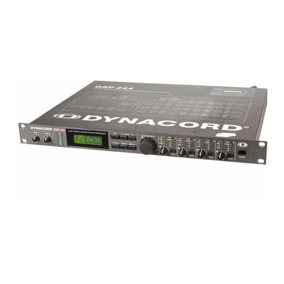
- Page 1 OWNER’S MANUAL DSP 244 24 BIT DIGITAL SOUND SYSTEM PROCESSOR...
-
Page 2: Important Safety Instructions
IMPORTANT SAFETY INSTRUCTIONS Read these instructions. Keep these instructions. Heed all warnings. Follow all instructions. Do not use this apparatus near water. Clean only with a damp cloth. Do not block any of the ventilation openings. Install in accordance with the manufactures instructions. Do not install near any heat sources such as radiators, heat registers, stoves, or other apparatus that produce heat. -
Page 3: Table Of Contents
6. CONFIGURATIONS OF THE DSP 244........ -
Page 4: Introduction
I N T R O D U C T I O N 1. INTRODUCTION First of all, we would like to thank you for and congratulate you on buying the DYNACORD Digital Sound System Processor DSP 244. To ensure an optimum in the performance of the appliance and to prevent any damage resulting from erroneous or inadvertent handling or operation, please read this owner’s... -
Page 5: Controls And Connections
1, Control INPUT 1 / INPUT 2 Rotary controls to set the input levels of the inputs 1 and 2 of the DSP 244. The input signal can be amplified by up to 6 dB (control set to its clockwise margin) or attenuated by any degree. - Page 6 11, OUTPUT-controls 1 - 4 These rotary controls are used to set the output levels of channels 1 to 4, allowing to match the DSP 244 to the input levels of the devices chained in sequence. Correctly setting these controls results in an improved S/N ratio.
-
Page 7: Rear Panel
These are the 2 balanced inputs of the DSP 244. Each input employs a Direct Out connector which allows to feed the unaltered input signal to another DSP 244 or to any other device that needs to be operated with the unaltered source signal. In stereo or dual mode as well as in the monaural sub woofer mode, both connectors (LEFT / RIGHT) have to be connected accordingly. -
Page 8: Installation And Connections
3. INSTALLATION AND CONNECTIONS Correct connections is a vital factor in achieving the best results with the DSP 244. Before switching on the power you have to connect the supplied European standard mains cord to the DSP 244 and your mains wall outlet. -
Page 9: First Operation
-12dB and -6dB. The CLIP-LED’s indicate clipping of the AD-converter and should not light at all or at least only very briefly. When driving the DSP 244 below the mentioned range, its outstanding S/N ratio is not optimally used, resulting in probably audible system... -
Page 10: Quick Start
PROGRAM SELECTION Together with the DSP 244 you receive a listing of all available factory presets. In case you are using a DYNACORD loudspeaker system that is listed, just select the corresponding program number and your PA-system is optimally configured. - Page 11 LOUDSPEAKER EQUALIZATION The DSP 244 embodies 4 EQs per channel for each output channel allowing to optimally match the frequency response for the connected loudspeaker components; similar to the factory preset programs.
-
Page 12: Compressor / Limiter Settings
Pressing another OUTPUT control selects the control’s corresponding output channel. MATCHING THE FREQUENCY RESPONSE Using the Master EQs in the input channels of the DSP 244, the PA-system can be easily matched to various environmental and acoustical conditions. In many cases, a graphic equalizer which normally is employed to perform this task is not needed any longer. -
Page 13: Configurations Of The Dsp 244
If you do not want to use one of the pre-defined configurations, you have also the possibility to operate the DSP 244 in Full Edit mode. This mode offers access to all parameters and basically any input/output routing can be programmed. Additionally, the output assignment (output function - Sub, Lo, Mid, Hi, Fullrange) is also freely definable. -
Page 14: Stereo 2 Way
C O N F I G U R A T I O N S O F T H E D S P 2 4 4 6.1 Stereo 2 Way This configuration generally represents a 2-way stereo frequency crossover, where IN 1 serves as the left input channel and IN 2 as the right input channel. -
Page 15: Way + Fullrange
C O N F I G U R A T I O N S O F T H E D S P 2 4 4 6.3 3 Way + Fullrange The 3-Way + Fullrange configuration is a 3-way monaural x-over with additional full range output where IN 1 serves as input channel. -
Page 16: In-4
C O N F I G U R A T I O N S O F T H E D S P 2 4 4 6.5 3 Way / Independent Sub + Fullrange As well as the two previous configurations, this configuration also represents a 3-way frequency crossover with additional full range output, with the difference that the Sub-range channel OUT 1 gets its signal-feed from the input channel IN 2. - Page 17 C O N F I G U R A T I O N S O F T H E D S P 2 4 4 6.7 2-IN-4 In this configuration, all 4 outputs are configured for full range operation. OUT 1 and OUT 2 get their signal-feed from the input channel IN 1 while OUT 3 and OUT 4 are fed from the input channel IN 2.
-
Page 18: Operation
The rotary encoder with push-button function for fast editing of parameter values, 6 function keys, and the push-button function of the output level controls OUT 1 - 4 are the main controls of the DSP 244. With EDIT, OPTION, STORE and RECALL you are able to branch off to and also return from the corresponding menus. -
Page 19: Program Selection
7.1 PROGRAM SELECTION The DSP 244 offers 30 user-definable program presets (U01 - U30) and up to 50 factory pre-programmed presets (F01-F50). Altogether you have the possibility to choose from this selection of up to 80 different programs. CAUTION: A program also defines the configuration and therefore also assignment of the inputs and outputs of the DSP 244. - Page 20 O P E R A T I O N 3. Whenever the function block in the first line is selected, you are able to select another function block by using the rotary encoder (10). Pressing one of the controls OUT 1 - 4 lets you directly select the function blocks of the corresponding output channel.
-
Page 21: Store Programs And Program Names
7.3 STORE PROGRAMS AND PROGRAM NAMES Whether you want to store an edited program, alter the name of a program, or copy a program from one preset location to another - in all cases the necessary procedure is the same. Pressing the STORE key (8) always starts and executes the saving procedure. -
Page 22: Modifying Factory-Preset-Programs
7.4 MODIFYING FACTORY PRESET PROGRAMS The easiest and quickest way to achieve good results with the DSP 244 is the use of a factory preset program. Factory preset programs are carefully designed, factory-pre-set programs that are stored non-volatile in the FLASH memory of the DSP 244. Just select the preset that matches your loudspeaker combination and the DSP 244 automatically sets all parameters to their optimal values matching your components. -
Page 23: Parameters
8. PARAMETERS Depending on its configuration and operation mode, the DSP 244 offers a selection of more or less different parameters. The parameters are assigned to the input channels IN1, IN2, IN1+2 and to the 4 output channels OUT1, OUT2, OUT3, OUT4. The channel number is indicated in the top left corner of the display while the function block (MASTER EQ, MASTER DELAY, CHANNEL EQ, etc.) is shown next to the... -
Page 24: Parameter Access
OUT4 HIPASS Y E S XOVER OUT4 LOPASS XOVER YES: Parameter is available Parameter is not available ) STANDARD Mode can be selected in the DSP 244 Editor software STANDARD Mode 3 Way 3 Way 3 Way Independ. Mono Sub +... -
Page 25: Parameter Link-Table
MASTER EQ1-5 Both input channels of the DSP 244 employ a 5-Band parametric EQ, each, which provide extreme flexibility in the programming of full range equalization to match the sound reinforcement system to different acoustic conditions and venues which in most cases makes the need for post-mix graphic equalization unnecessary. - Page 26 B6-alignment; i. e. an increase in the response in the cutoff frequency range. The following examples are meant to show you the effect of different parameter settings. The DSP 244 editor software allows you to make your own adjustments via PC or notebook computer and monitor the resulting frequency response on the computer screen.
- Page 27 PEQ: f = 1kHz, Gain = -12dB Low Shelving Filter (LOSLV): High Shelving Filter (HISLV): Low Shelving Filter (LOSLV): High Shelving Filter (HISLV): Hi-Pass Filter (HIPASS): Lo-Pass Filter (LOPASS): Q = 0.5, 1.0, 5.0, 20.0 f = 200Hz, Slope = 6dB f = 2000Hz, Slope = 6dB f = 200Hz, Slope = 12dB, f = 2000Hz, Slope = 12dB,...
-
Page 28: Master Delay
ROUTING Any combination of input channels can be assigned to the outputs of the DSP 244. The routing defines which input signal is fed to either one of the output channels (OUT1, OUT2, OUT3, OUT4). Besides routing the signals of the two input channels IN1 and IN2 to one of the outputs, it is also possible to assign the summed, monaural audio signal of both inputs IN1+2 to one of the outputs. - Page 29 CHANNEL EQ1-4 The four output channels of the DSP 244 employ a 4-band parametric EQ each which allow to program additional equalization for the individual frequency ranges. This guarantees the optimum frequency response that is matched to the connected loudspeaker components.
- Page 30 Examples for the settings of different filter types are provided in the paragraph MASTER EQ1-5. You are also able to program your own settings of the DSP 244 via PC or notebook computer and monitor the resulting frequency response on the computer screen. The following example shows the phase response of Allpass filters with different parameter settings.
- Page 31 HIPASS X-OVER The frequency crossover filter consists of a low pass filter in one channel and a high pass filter in the adjacent channel. Here, the frequency x-over filter’s Hi-Pass parameters are set. The parameters of the corresponding Lo-Pass should be set to the same values. An x-over filter provides the parameters “Type” and “f”.
- Page 32 P A R A M E T E R S The f parameter (frequency) sets the x-over Lo-Pass filter’s cutoff frequency. The corresponding Hi-Pass filter should be set to the same cutoff frequency. Pol defines the polarity of the corresponding channel. Depending on the characteristic of the frequency crossover filter, inverting the polarity of a channel’s signal may become necessary;...
-
Page 33: Channel Delay
CHANNEL DELAY These delays are provided in the output channels OUT1 - OUT4. They are used to compensate differences in loudspeaker dispersion plains that can be cabinet imminent or result from the positioning of individual loudspeaker cabinets or arrays. The delay time or acoustical distance is displayed in milliseconds, microseconds, feet, inches, meters, or centimeters. - Page 34 P A R A M E T E R S COMPRESSOR The compressor automatically reduces level peaks above a certain threshold and therefore provides reliable protection against power amplifier clipping and damaging the connected loudspeaker systems. Parameter Thrsh 0.27V - 8.70V 1/1.0, 1/1.4, 1/2.0, 1/4.0, 1/8.0 Attack 0ms - 99ms...
- Page 35 LIMITER The limiter provides additional protection against the occurrence of clipping and overload conditions. The maximum level of the audio signal is limited to the set threshold value. The short attack times guarantee that even sudden peak levels are effectively attenuated. Parameter Thrsh 0.27V - 8.70V...
-
Page 36: Option-Functions
The LCD contrast or viewing angle can be set in a range of -10 (bottom view) and +10 (top view). 9.2 EDIT MODE SELECTION This page allows you to choose the operation mode which the DSP 244 is operated in. The display shows the following selection menu: When you select No edit, editing and program selection is not possible. -
Page 37: Compressor And Limiter Threshold Unit
9.5 EDIT PROTECTION The DSP 244 offers the possibility for edit-protection. Once this protection mode is enabled, internal settings cannot be altered unless the required code-number is entered first. In this way, the appliance is effectively protected against inadvertent or faulty operation. -
Page 38: Temperature Unit Settings
Press the STORE twice to acknowledge this dialog. When trying to change one of the appliance’s settings, SYSTEM IS LOCKED! appears on the display, indicating that the DSP 244’s operating system is blocked for entries via the numeric keys or the rotary encoder. -
Page 39: Send Parameters
To RS232: During editing and program change, data is transmitted via the RS-232 port. In case that you have connected a PC with the DSP 244 Editor software installed, you are able to monitor changes in the setting on the PC-screen. -
Page 40: Nrs 90246 Contact Closure Interface Settings
MIDI transmission channel (MIDI TX CHANNEL). 9.10 NRS 90246 CONTACT CLOSURE INTERFACE settings Amongst others, the DSP 244 is prepared for retrofitting an optional NRS 90246 Contact Closure Interface, which can be used instead of the RS-232 interface. The Contact Closure Interface offers eight control inputs that can be used for program change commands or Soft-Mute. -
Page 41: Nrs 90247 Rs-485 Interface Settings
Amongst other available options, retrofitting the NRS 90247, RS-485 interface in the DSP 244 instead of the RS-232 interface is possible as well. The RS-485 interface allows configuring, controlling and monitoring up to 31 DSP 244 from a PC. In that case, assigning individual RS-485 IDs to each DSP 244 is necessary. -
Page 42: Specifications
SPECIFICATIONS 10. SPECIFICATIONS 10.1 TECHNICAL SPECIFICATIONS Mains voltage Power consumption Safety class Inputs Input voltage (nominal) Max. input voltage Input impedance Common mode rejection AD-conversion Outputs Output voltage (nominal) Max. output voltage Output impedance Min. load impedance DA-conversion Frequency response S/N ratio Distortion without transformer Distortion with transformer... -
Page 43: Midi
DEV_CODE REVISION The DSP 244 sends this ID-Code as a reply to an Identity Request. Transmitted are the DYNACORD ID-No. 48, the DSP 244 UNIT-ID No. 24, a 3-Byte Unit-Code and the Revision No. Description n = MIDI Channel 0 - 15 1 .. - Page 44 Beschreibung System Exclusive DYNACORD ID: No 48 n = MIDI Channel 0 - 15 (7F = All Channels) DSP 244 ID: No 24 Function ID: Serial Link / Parser ASCII Code Line for Command Parser (up to 120 Byte) Checksum for DATA (7 Bit, 2’s Complement)
- Page 45 UNIT-ID /ID1/ IN1/ IN2/ INSUM/ OUT1/ OUT2/ ... OUT4/ MISC/ TEMPERATURE_UNIT /ID2/ ... /ID32/ For Type = Allpass: Slope = 6: First Order Allpass Slope = 12: Second Order Allpass Example: /ID3/ OUT1/ XOVER/ HIPASS/ FREQ 1500 C o m m a n d P a r s e r C o d e T a b l e Tree DELAY EQ1/...
-
Page 46: Installation Manual For The Input Transformer (Nrs 90244)
1 x Screw M2,5 x 6 Installation instructions NRS 90244: 1. Switch the DSP 244’s power off and unplug the mains cord. 2. Remove the cover plate after unscrewing 2 screws on the top, 4 on the sides, and 3 on the rear. -
Page 47: Installation Manuals For Interface Cards
4 x Screws M3 x 6 Installation instructions NRS 90246, NRS 90247: 1. Switch the DSP 244’s power off and unplug the mains cord. 2. Remove the cover plate after unscrewing 2 screws on the top, 4 on the sides, and 3 on the rear. -
Page 48: Block Diagram
B L O C K D I A G R A M M / B L O C K D I A G R A M 10-7... -
Page 49: Flow Diagram
F L U S S D I A G R A M M / F L O W D I A G R A M 10-5... -
Page 50: Dimensions
A B M E S S U N G E N / D I M E N S I O N S Abmessungen / Dimensions (in mm) 10-6... -
Page 51: Warranty
Toute modification ou intervention effec- tuée par une personne non qualifiée entraîne la résiliation automatique de la garantie. • Telefax (09421) 706-265 28. 10. 2001 / 356 273 REV. 5 Internet: http:// www.dynacord.de...
Need help?
Do you have a question about the DSP 244 and is the answer not in the manual?
Questions and answers