Table of Contents
Advertisement
NF61V Micro AM2 SE/NF61S Micro AM2 SE
Setup Manual
FCC Information and Copyright
This equipment has been tes ted and found to comply with the limits of a Class
B digital devic e, purs uant to Part 15 of the FCC Rules . T hese limits are designed
to provide reasonable protec tion against harmful interference in a residential
installation. T his equipment generates , uses and can radiate radio frequency
energy and, if not ins talled and used in accordance with the instructions , may
cause harmful interference to radio communications . There is no guarantee
that interference will not occur in a particular ins tallation.
The vendor makes no representations or warranties with respec t to the
contents here and s pecially disclaims any implied warranties of merchantability
or fitness for any purpose. Further the vendor reserves the right to revise this
publication and to make c hanges to the c ontents here without obligation to
notify any party beforehand.
D uplication of this publication, in part or in whole, is not allowed without first
obtaining the vendor's approval in writing.
The content of this user's manual is subject to be c hanged without notice and
we will not be res ponsible for any mis takes found in this user's manual. All the
brand and produc t names are trademarks of their respec tive companies .
Advertisement
Chapters
Table of Contents

Related Manuals for Biostar NF61S MICRO AM2 SE


Summary of Contents for Biostar NF61S MICRO AM2 SE
- Page 1 NF61V Micro AM2 SE/NF61S Micro AM2 SE Setup Manual FCC Information and Copyright This equipment has been tes ted and found to comply with the limits of a Class B digital devic e, purs uant to Part 15 of the FCC Rules . T hese limits are designed to provide reasonable protec tion against harmful interference in a residential installation.
-
Page 2: Table Of Contents
Table of Contents Chapter 1: Introduction ..........1 Before You Start..............1 Package Checklist..............1 Motherboard Features............2 Rear Panel Connectors (Ver 6.x )..........4 Rear Panel Connectors (Ver 5.x ) ..........4 Motherboard Layout (Ver 6.x )..........5 Motherboard Layout (Ver 5.x )..........6 Chapter 2: Hardware Installation ...... -
Page 3: Chapter 1: Introduction
NF61V Micro A M2 SE/NF61S Micro A M2 SE CHAPTER 1: INTRODUCTION EFORE T ART Thank you for choosing our product. Be fore you start installing the mothe rboard, please make sure you follow the instructions be low: Prepare a dry and stable work ing environment with sufficie nt lighting. - Page 4 Motherboard Manual OT HERBOARD EAT URES NF61V Micr o A M2 SE NF61S Micro A M2 SE Socket AM2 Socket AM2 AMD Sempron / Ath lon 64 / Ath lon 64 FX / AMD Sempron / Ath lon 64 / Ath lon 64 FX / Althlon 64 X2 processors Althlon 64 X2 processors Supports Hyper Tran sport and Cool=n =Quiet...
- Page 5 Windows 2000 / XP / VISTA Windows 2000 / XP / VISTA OS Support Biostar Reserves th e righ t to add or remove Biostar Reserves th e righ t to add or remove support for any OS With or withou t notice.
- Page 6 Motherboard Manual ANEL ONNECT ORS PS/2 Mouse Line In/ Surround Line Out Mic In 1/ Bass/ Center PS/2 COM1 USBX2 USBX2 Keyboard ANEL ONNECT ORS PS/2 LA N Mouse PS/2 USBX2 USB X2 COM1 Keybo ard Cente r Line In Re ar Line Out Side...
-
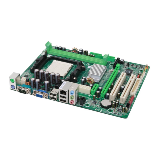
Page 7: Motherboard Layout (Ver 6.X )
NF61V Micro A M2 SE/NF61S Micro A M2 SE OT HERBOARD AYOUT JDDRII_22V1 JKBMS1 JCFAN1 JATXPWR2 JUSBV1 JUSB1 JUS BLAN1 JATXPWR1 MCP61V JAUDIO1 MCP61S JNFAN1(Optional) JAUDIOF1 PEX1_1 JCI 1(Opt ional) SAT A 2 SAT A 1 PEX16_1 JCMOS1 BAT1 PCI1 JUSB2 JSPDIF_IN1(Opt ional) BI OS... -
Page 8: Motherboard Layout (Ver 5.X )
Motherboard Manual OT HERBOARD AYOUT JDDRII_22V1 JKBMS1 JCFAN1 JATXPWR2 JUSBV1 JUSB1 JUS BLAN1 JATXPWR1 MCP61V JAUDIO1 MCP61S JNFAN1(Optional) JAUDIOF1 PEX1_1 JCI 1(Opt ional) SAT A 2 SAT A 1 PEX16_1 JCMOS1 BAT1 PCI1 JUSB2 JSPDIF_IN1(Opt ional) BI OS Super I/O PCI2 Codec JUSB3... -
Page 9: Chapter 2: Hardware Installation
NF61V Micro A M2 SE/NF61S Micro A M2 SE CHAPTER 2: HARDWARE INSTALLATION (CPU) NST ALLING ENT RAL ROCESSING Step 1: Remove the socket protection cap. Step 2: Pull the lever toward direction A from the socket and then raise the lever up to a 90-degree angle. - Page 10 Motherboard Manual Step 4: Hold the CPU down firmly, and then close the lever toward direct B to complete the installation. Step 5: Put the CPU Fan on the CPU and buckle it. Connect the CPU FAN power cable to the JCFAN1. This completes the installation.
-
Page 11: Fan Headers
NF61V Micro A M2 SE/NF61S Micro A M2 SE FAN H EADERS These fan headers support cooling-fans built in the computer. The fan cable and connector may be different according to the fan manufacturer. Connect the fan cable to the connector while matching the black wire to pin#1. -
Page 12: Installing System Memory
Motherboard Manual NST ALLING YST EM EMORY A. Memory Modules DIMMA1 DIMMB1 Unlock a DIMM slot by pressing the retaining clips outward. Align a DIMM on the slot such that the notch on the DIMM matches the break on the Slot. Insert the DIMM vertically and firmly into the slot until the retaining chip snap back in place and the DIMM is properly seated. - Page 13 NF61V Micro A M2 SE/NF61S Micro A M2 SE B. Memory Capacity DIMM Socket DDR Module Total Memory Size Location DIMMA1 256MB/512MB/1024MB *1 Max memory 2GB. DIMMB1 256MB/512MB/1024MB *1 C. Dual Channel Memory installation To trigger the Dual Channel f unction of the motherboard, the memory module must meet the following requirements: Install memory module of the same density in pair, shown in the following table.
-
Page 14: Connectors And Slots
Motherboard Manual ONNECT ORS AND LOT S FDD1: Floppy Disk Conne ctor The motherboard prov ides a standard floppy disk connector that supports 360K, 720K, 1.2M, 1.44M and 2.88M floppy disk ty pes. This connector supports the prov ided f loppy drive ribbon cables. IDE1: Hard Disk Conne ctor The motherboard has a 32-bit Enhanced IDE Controller that prov ides PIO Mode 0~4, Bus Master, and Ultra DMA 33/66/100/133 f unctionality. - Page 15 Maximum theoretical realized bandwidth of 250MB/s simultaneously per direction, f or an aggregate of 500MB/s totally. PEX16_1: PCI-Express x16 Slot (x8 Spee d) (for NF61S Micro AM2 SE) PCI-Express 1.0a compliant. Maximum theoretical realized bandwidth of 2GB/s simultaneously per direction, f or an aggregate of 4GB/s totally.
-
Page 16: Chapter 3: Headers & Jumpers Setup
Motherboard Manual CHAPTER 3: HEADERS & JUMPERS SETUP OW T O ET UP UMPERS The illustration shows how to set up jumpers. When the jumper cap is placed on pins, the jumper is “close”, if not, that means the jumper is “open”. - Page 17 NF61V Micro A M2 SE/NF61S Micro A M2 SE JATXPWR1: ATX Powe r Source Conne ctor This connector allows user to connect 24-pin power connector on the ATX power supply. Assignment Assignment +3.3V +3.3V -12V +3.3V Ground Ground PS_ON Ground Ground Ground Ground...
-
Page 18: Power Source Headers For Usb Ports
Motherboard Manual JUSB2/JUSB3: Heade rs for USB 2.0 Ports at Front Panel This header allows user to connect additional USB cable on the PC f ront panel, and also can be connected with internal USB devices, like USB card reader. Assignment +5V (fused) +5V (fused) - Page 19 NF61V Micro A M2 SE/NF61S Micro A M2 SE JAUDIO F1: Front Panel Audio Heade r This header allows user to connect the front audio output cable with the PC f ront panel. It will disable the output on back panel audio connectors. Assignment Mic in Ground...
- Page 20 Motherboard Manual JCMO S1: Cle ar CMOS Heade r By placing the jumper on pin2-3, it allows user to restore the BIOS saf e setting and the CMOS data, please carefully f ollow the procedures to avoid damaging the motherboard. Pin 1-2 Close: Normal Operation (default).
- Page 21 NF61V Micro A M2 SE/NF61S Micro A M2 SE JPRNT1: Printe r Port Connector This header allows you to connector printer on the PC. Assignment Assignment -Strobe Ground -ALF Data 6 Data 0 Ground -Error Data 7 Data 1 Ground -Init -ACK Data 2...
- Page 22 Motherboard Manual He ade r for Memory ove r-voltage: JDDRII_22V1 When processing Memory ov er-voltage, please place the jumper to pin2-3 Closed. The Def ault setting is Pin 1-2 Closed. Pin 1-2 Cl ose: Normal status (defa ult). Pin 2-3 Cl ose: Memory voltag e 2.2V.
- Page 23 NF61V Micro A M2 SE/NF61S Micro A M2 SE JSPDIF_IN1: Digital Audio-in Conne ctor (optional) This connector allows user to connect the PCI bracket SPDIF input header. Assignment SPDIF_IN Ground...
-
Page 24: Chapter 4: Raid Functions
Motherboard Manual CHAPTER 4: RAID FUNCTIONS PERAT ION YST EM Supports Windows XP Home/Prof essional Edition, and Windows 2000 Professional. RRAYS RAID supports the following types of RAID arrays: RAID 0: RAID 0 defines a disk striping scheme that improves disk read and write times for many applications. - Page 25 NF61V Micro A M2 SE/NF61S Micro A M2 SE RAID 1: Every read and write is actually carried out in parallel across 2 disk drives in a RAID 1 array system. The mirrored (backup) copy of the data can reside on the same disk or on a second redundant drive in the array.
-
Page 26: Chapter 5: Useful Help
Motherboard Manual CHAPTER 5: USEFUL HELP RIVER NST ALLAT ION OT E After you installed your operating system, please insert the Fully Setup Driver CD into your optical drive and install the driver for better system performance. You will see the following window after you insert the CD The setup guide will auto detect your motherboard and operating system. -
Page 27: Award Bios Beep Code
BIOS contents are corrupted. In this Case, please follow the procedure below to restore the BIOS: 1. Make a bootable floppy disk. 2. Download the Flash Utility “AWDFLASH.exe” from the Biostar website: www.biostar.com.tw 3. Confirm motherboard model and download the respectively BIOS from Biostar website. - Page 28 Motherboard Manual B. CPU Overheated If the system shutdown automatically after power on system for seconds, that means the CPU protection function has been activated. When the CPU is over heated, the motherboard will shutdown automatically to avoid a damage of the CPU, and the system may not power on again.
-
Page 29: Troubleshooting
NF61V Micro A M2 SE/NF61S Micro A M2 SE ROUBLESHOOT ING Probable Solution No power to the system at all Make sure power cable is Power light don’t illuminate, f an securely plugged in. inside power supply does not turn Replace cable. -
Page 30: Chapter 6: Warpspeeder
Motherboard Manual WARPSPEEDER™ CHAPTER 6: NT RODUCT ION [WarpSpeeder™], a new powerful control utility, features three user-friendly functions including Overclock Manager, Overvoltage Manager, and Hardware Monitor. With the Overclock Manager, users can easily adjust the frequency they prefer or they can get the best CPU performance with just one click. The Overvoltage Manager, on the other hand, helps to power up CPU core voltage and Memory voltage. -
Page 31: Installation
NF61V Micro A M2 SE/NF61S Micro A M2 SE NST ALLAT ION 1. Execute the setup execution file, and then the following dialog will pop up. Please click “Next” button and follow the default procedure to install. 2. When you see the following dialog in setup procedure, it means setup is completed. -
Page 32: Warpspeeder
Motherboard Manual 6.4 W ™ PEEDER 1. Tray Icon: Whenever the Tray Icon utility is launched, it will display a little tray icon on the right side of Windows Taskbar. This utility is responsible for conveniently invoking [WarpSpeeder™] Utility. You can use the mouse by clicking the left button in order to invoke [WarpSpeeder™] directly from the little tray icon or you can right-click the little tray icon to pop up a popup menu as following figure. - Page 33 NF61V Micro A M2 SE/NF61S Micro A M2 SE 2. Main Panel If you click the tray icon, [WarpSpeeder™] utility will be invoked. Please refer to the following figure; the utility’s first window you will see is Main Panel. Main Panel contains fe ature s as follows: a.
- Page 34 Motherboard Manual 3. Voltage Panel Click the Voltage button in Main Panel, the button will be highlighted and the Voltage Panel will slide out to up as the following figure. In this panel, you can decide to increase CPU core voltage and Memory voltage or not.
- Page 35 NF61V Micro A M2 SE/NF61S Micro A M2 SE 4. Overclock Panel Click the Overclock button in Main Panel, the button will be highlighted and the Overclock Panel will slide out to left as the following figure. O ve rclock Panel contains the these features: a.
- Page 36 Motherboard Manual “Auto-overclock button”: User can click this button and [WarpSpeeder™] will set the best and stable performance and frequency automatically. [WarpSpeeder™] utility will execute a series of testing until system fail. Then system will do fail-safe reboot by using Watchdog function. After reboot, the [WarpSpeeder™] utility will restore to the hardware default setting or load the verified best and stable frequency according to the Recovery Dialog’s setting.
- Page 37 NF61V Micro A M2 SE/NF61S Micro A M2 SE 6. About Panel Click the “about” button in Main Panel, the button will be highlighted and the About Panel will slide out to up as the following figure. In this panel, you can get model name and detail information in hints of all the chipset that are related to overclocking.
-
Page 38: Appendencies: Spec In Other Language
Motherboard Manual APPENDENCIES: SPEC IN OTHER LANGUAGE ERMAN NF61V Micr o A M2 SE NF61S Micro A M2 SE Sockel AM2 Sockel AM2 AMD Ath lon 64 / Ath lon 64 FX / Athlon 64 x2/ AMD Ath lon 64 / Ath lon 64 FX / Athlon 64 x2/ Sempron Prozessoren Sempron Prozessoren Unterstü... - Page 39 Unterstü tzt RAID 0 / 1 Windows 2000 / XP / VISTA Windows 2000 / XP / VISTA OS-Un terst Biostar beh ält sich das Rech t vor, ohne Biostar beh ält sich das Rech t vor, ohne ützung Ankündigung die Un terstützung für ein Ankündigung die Un terstützung für ein...
-
Page 40: France
Motherboard Manual RANCE NF61V Micr o A M2 SE NF61S Micro A M2 SE Socket AM2 Socket AM2 Processeu rs AMD Athlon 64 / Athlon 64 FX / Processeu rs AMD Athlon 64 / Athlon 64 FX / Ath lon 64 x2/ Sempron Ath lon 64 x2/ Sempron Prend en charge Hyper Tran sport et Cool’n ’Quiet Prend en charge Hyper Tran sport et Cool’n ’Quiet... - Page 41 Windows 2000 / XP / VISTA Windows 2000 / XP / VISTA Support SE Biostar se réserve le droit d'ajouter ou de Biostar se réserve le droit d'ajouter ou de supprimer le support de SE avec ou san s préavis.
-
Page 42: Italian
Motherboard Manual T ALIAN NF61V Micr o A M2 SE NF61S Micro A M2 SE Socket AM2 Socket AM2 Processori AMD Athlon 64 / Athl on 64 FX Processori AMD Athlon 64 / Athl on 64 FX / Athlon 64 x 2/ Sempr on / Athlon 64 x 2/ Sempr on Supporto di Hyper Tra nsport e Supporto di Hyper Tra nsport e... - Page 43 Supporto RAID 0 / 1 Windows 2000 / XP / VISTA Windows 2000 / XP / VISTA Sistemi Biostar si riserva il diritto di aggiungere o Biostar si riserva il diritto di aggiungere o operativi rimuovere il supporto di qualsiasi sistema...
-
Page 44: Spanish
Motherboard Manual PANISH NF61V Micr o A M2 SE NF61S Micro A M2 SE Conector AM2 Conector AM2 Procesadores AMD Athlon 64 / Ath lon 64 FX / Procesadores AMD Athlon 64 / Ath lon 64 FX / Ath lon 64 x2/ Sempron Ath lon 64 x2/ Sempron Soporta las tecnologías Hyper T ran sport y Soporta las tecnologías Hyper T ran sport y... - Page 45 Windows 2000 / XP / VISTA Windows 2000 / XP / VISTA sistema Biostar se reserva el derecho de añ adir o retirar Biostar se reserva el derecho de añ adir o retirar operativo el soporte de cualqu ier SO con o sin aviso previo.
-
Page 46: Portuguese
Motherboard Manual ORT UGUESE NF61V Micr o A M2 SE NF61S Micro A M2 SE Socket AM2 Socket AM2 Processadores AMD Ath lon 64 / Ath lon 64 FX / Processadores AMD Ath lon 64 / Ath lon 64 FX / Ath lon 64 x2/ Sempron Ath lon 64 x2/ Sempron Suporta as tecn ologias Hyper Tran sport e... - Page 47 Windows 2000 / XP / VISTA Windows 2000 / XP / VISTA Sistemas A Biostar reserva-se o direito de adicionar ou A Biostar reserva-se o direito de adicionar ou operativos remover suporte para qu alquer sistema remover suporte para qu alquer sistema suportados operativo com ou sem aviso prévio.
-
Page 48: Polish
Motherboard Manual OLISH NF61V Micr o A M2 SE NF61S Micro A M2 SE Socket AM2 Socket AM2 AMD Ath lon 64 / Ath lon 64 FX / Athlon 64 x2/ AMD Ath lon 64 / Ath lon 64 FX / Athlon 64 x2/ Procesor Sempron Procesory Sempron Procesory... - Page 49 Obsługa RAID 0 / 1 Obsluga Windows 2000 / XP / VISTA Windows 2000 / XP / VISTA systemu Biostar zastrzega sobie prawo dodawania lub Biostar zastrzega sobie prawo dodawania lub operacyjne odwoływania obsługi dowoln ego systemu odwoływania obsługi dowoln ego systemu operacyjnego bez powiadomien ia.
-
Page 50: Russian
Motherboard Manual USSIAN NF61V Micr o A M2 SE NF61S Micro A M2 SE Гнездо AM2 Гнездо AM2 Процессоры AMD Ath lon 64 / Athlon 64 FX / Процессоры AMD Ath lon 64 / Athlon 64 FX / (центральн ый Althlon 64 X2 Althlon 64 X2 процессор) - Page 51 Поддержка RAID 0 / 1 характери стики Windows 2000 / XP / VISTA Windows 2000 / XP / VISTA Biostar сохраняет за собой право добавлят ь Biostar сохраняет за собой право добавлят ь Поддержка OS или удалять средст ва обесп ечения для OS с...
-
Page 52: Arabic
Motherboard Manual RABIC NF61S Micro A M2 SE NF61V Micr o A M2 SE ﻡﻘﺒﺲAM2 ﻡﻘﺒﺲAM2 ﻡﻌ ﺎ ﻟﺠﺎتAMD Athlon 64 / Athlon 64 FX / Ath lon 64 ﻡﻌ ﺎ ﻟﺠﺎتAMD Athlon 64 / Athlon 64 FX / Ath lon 64 اﻟﻤ... -
Page 53: Pci Express X16
ﻡﻢ ارﺗﻔﺎع ﻡﻢ ﻋﺮض ﻡﻢ ا ﻟ ﻠﻮﺣﺔ ﺣﺠﻢ Windows 2000 / XP / VISTA Windows 2000 / XP / VISTA ا ﻟﺘﺸﻐﻴﻞ أﻥﻈﻤﺔ دﻋﻢ ﺗﺤﺘﻔﻆBiostar ﺗﺤﺘﻔﻆBiostar ﺏﺈﺥﻄﺎر ﺗﺸﻐﻴﻞ ﻥﻈﺎم ﻷي اﻟﺪﻋﻢ إزاﻟﺔ أو إﺿﺎﻓﺔ ﻓﻲ ﺏﺤﻘﻬﺎ ﺏﺈﺥﻄﺎر... -
Page 54: Japanese
Motherboard Manual APANESE NF61V Micr o A M2 SE NF61S Micro A M2 SE Socket AM2 Socket AM2 AMD Ath lon 64 / Ath lon 64 FX / Athlon 64 x2/ AMD Ath lon 64 / Ath lon 64 FX / Athlon 64 x2/ Sempron プロセッサ... - Page 55 207 mm (幅) X 244 mm (高さ) NVIDIA nTunes NVIDIA nTunes 特殊機能 RAID 0 / 1 のサポート RAID 0 / 1 のサポート Windows 2000 / XP / VISTA Windows 2000 / XP / VISTA OSサポート Biostarは事前のサポートなしにOSサポートを追加ま Biostarは事前のサポートなしにOSサポートを追加ま たは削除する権利を留保します。 たは削除する権利を留保します。 2006/10/30...
- Page 56 NF61V Micro AM2 SE / NF61S Micro AM2 SE BIOS Setup Table of Contents BIOS Setup ....................2 1 Main Menu....................4 2 Standard CMOS Features..............7 3 Advanced BIOS Features ...............9 4 Advanced Chipset Features..............15 5 Integrated Peripherals................17 6 Power Management Setup..............23 7 PnP/PCI Configurations...............27...
-
Page 57: Bios Setup
NF61V Micro AM2 SE / NF61S Micro AM2 SE BIOS Setup BIOS Setup Introduction The purpose of this manual is to describe the settings in the Award™ BIOS Setup program on this motherboard. The Setup program allows users to modify the basic system configuration and save these settings to CMOS RAM. -
Page 58: Pci Bus Support
NF61V Micro AM2 SE / NF61S Micro AM2 SE BIOS Setup PCI Bus Support This AWARD BIOS also supports Version 2.1 of the Intel PCI (Peripheral Component Interconnect) local bus specification. DRAM Support DDR SDRAM (Double Data Rate Synchronous DRAM) is supported. -
Page 59: Main Menu
NF61V Micro AM2 SE / NF61S Micro AM2 SE BIOS Setup 1 Main Menu Once you enter Award BIOS™ CMOS Setup Utility, the Main Menu will appear on the screen. The Main Menu allows you to select from several setup functions. -
Page 60: Load Optimized Defaults
NF61V Micro AM2 SE / NF61S Micro AM2 SE BIOS Setup Advanced Chipset Features This submenu allows you to configure special chipset featu res. Integrated Peripherals This submenu allows you to configure cert ain IDE hard drive options and Programmed Input/ Output features. -
Page 61: Set User Password
NF61V Micro AM2 SE / NF61S Micro AM2 SE BIOS Setup Set User Password If the Supervisor Password is not set, then the User Password will function in the same way as the Supervisor Password. If the Supervisor Password is set and the User Password is set, the “User”... -
Page 62: Standard Cmos Features
NF61V Micro AM2 SE / NF61S Micro AM2 SE BIOS Setup 2 Standard CMOS Features The items in Standard CMOS Setup Menu are divided into several categori es. Each category includes no, one or more than one setup items. Use the arrow keys to highlight the item and then use the<PgUp>... - Page 63 NF61V Micro AM2 SE / NF61S Micro AM2 SE BIOS Setup Item Options Description disk drive installed in your Driv e B 1.2M, 5.25 in sy stem. 720K, 3.5 in 1.44M, 3.5 in 2.88M, 3.5 in None EGA/VGA CGA 40...
-
Page 64: Advanced Bios Features
NF61V Micro AM2 SE / NF61S Micro AM2 SE BIOS Setup 3 Advanced BIOS Features Figure 3: Advanced BIOS Setup Cache Setup... - Page 65 NF61V Micro AM2 SE / NF61S Micro AM2 SE BIOS Setup CPU Internal Cache Depending on the CP U/chipset in use, you may be able to increase me mory access time with this option. Enabled (default) Enable cache. Disabled Disable cache.
- Page 66 NF61V Micro AM2 SE / NF61S Micro AM2 SE BIOS Setup Remov able Device Priority Select Removable Boot Device Priority. The Choices: Floppy Disks, Zip100, USB-FDD0, USB-FDD1, USB-ZIP0, USB-ZIP1, LS120. Hard Disk Boot Priority The BIOS will attempt to arrange the Hard Disk boot sequence automatically.You can change the Hard Disk booting sequence here.
- Page 67 NF61V Micro AM2 SE / NF61S Micro AM2 SE BIOS Setup CD-ROM Boot Priority TheChoices: Pri. Master, Pri. Slave, Sec. Master, Sec. Slave, USB-CDROM0, USB-CDROM1. First/Second/Third Boot Dev ice The BIOS will attempt to load the operating system in this order.
-
Page 68: Virus Warning
NF61V Micro AM2 SE / NF61S Micro AM2 SE BIOS Setup Virus Warning This option allows you to choose the VIRUS Warning feature th at is used to protect the IDE Hard Disk boot sector. If this function is enabled and an attempt is made to write to the boot sector, BIOS will display a warning message on the screen and sound an alarm beep. -
Page 69: Security Option
NF61V Micro AM2 SE / NF61S Micro AM2 SE BIOS Setup Security Option This option will enable only individuals with passwords to bring the system online and/or to use the CMOS Setup Utility. System: A password is required fo r the system to boot and is also required to access the Setup Utility. -
Page 70: Advanced Chipset Features
NF61V Micro AM2 SE / NF61S Micro AM2 SE BIOS Setup 4 Advanced Chipset Features This submenu allows you to configure the speci fic features o f the chipset installed on your system. This chipset manage bus speeds and access to system memory resources, such as DRAM. -
Page 71: System Bios Cacheable
NF61V Micro AM2 SE / NF61S Micro AM2 SE BIOS Setup K8<->NB HT Width This item allows you to select the K8<->NB HT Width The Choices:,Auto (default),[↓8 ↑8], [↓16 ↑16]. SATA /PCIE Spread Spectrum This item allows you to enable/disable the Spread Spectrum function. -
Page 72: Integrated Peripherals
NF61V Micro AM2 SE / NF61S Micro AM2 SE BIOS Setup 5 Integrated Peripherals Figure 5. Integrated Peripherals IDE Function Setup... - Page 73 NF61V Micro AM2 SE / NF61S Micro AM2 SE BIOS Setup RAID Config RAID Enable This option allows you to enable or disable RAID function. The Choices: Disabled (default), Enabled. S ATA 1/2 Primary/Secondary RAID This option allows you to enable or disable SATA A P rimary/Secondary RAID.
- Page 74 NF61V Micro AM2 SE / NF61S Micro AM2 SE BIOS Setup Primary Master/Slave UDMA Ultra DMA function can be implemented if it is supported by the IDE hard drives in your system. As well, your operating environment requires a DMA driver (Windows 95 or OSR2may need a third party IDE bus master driver).
-
Page 75: Onboard Device
NF61V Micro AM2 SE / NF61S Micro AM2 SE BIOS Setup Onboard Device USB Memory Type The item allows you select the type of USB Memory. The Choices: SHADOW (default), Base Memory(640K). USB Keyboard/ Storage Support This item allows you to support the USB legacy devices. - Page 76 NF61V Micro AM2 SE / NF61S Micro AM2 SE BIOS Setup MAC LAN This option allows you to control the onboard MAC LAN. The Choices: Auto (default), Disabled. MAC Media Interface This option allows you to control the onboard MAC Media Interface.
-
Page 77: Init Display First
NF61V Micro AM2 SE / NF61S Micro AM2 SE BIOS Setup Onboard Parallel Port This item allows you to determine access onboard parallel port controller with which I/O Address. The Choices: 378/IRQ 7 (default), 278/IRQ5, 3BC/IRQ7, Disabled. Parallel Port Mode This item allows you to determine how the parallel port should function. -
Page 78: Power Management Setup
NF61V Micro AM2 SE / NF61S Micro AM2 SE BIOS Setup 6 Power Management Setup The Power Management Setup Menu allows you to con figure you r system to utilize energy conservation and power up/power down featu res. Figure 6. Power Management Setup... -
Page 79: Power Management
NF61V Micro AM2 SE / NF61S Micro AM2 SE BIOS Setup Power Management This category allows you to select the power saving method and is directly related to the following modes: 1. HDD Power Down. 2. Suspend Mode. There are three options of Power Management, three of which have fixed mode settings Min. -
Page 80: Hpet Support
NF61V Micro AM2 SE / NF61S Micro AM2 SE BIOS Setup Soft-Off by PWR-BTN This item determines the behavior of system power button. Instant off turn o ff the power immediately, and Delay 4 Sec. will require you to press and hold the power button for 4 seconds to cut off the system power. -
Page 81: Power On Function
NF61V Micro AM2 SE / NF61S Micro AM2 SE BIOS Setup POWER ON Function This item allows you to choose the power on method. The Choices: Button Only (default), Password, Hot Key, Mouse Move/Click, Mouse Double Click, Any Key, Keyboard 98. -
Page 82: Pnp/Pci Configurations
NF61V Micro AM2 SE / NF61S Micro AM2 SE BIOS Setup 7 PnP/PCI Configurations This section describes configu ring the PCI bus system. PCI, or Personal Computer Interconnect, is a system which allows I/O devices to operate at speeds nearing the speed of the CPU itself uses when communicating with its own special components. -
Page 83: Resources Controlled By
NF61V Micro AM2 SE / NF61S Micro AM2 SE BIOS Setup and provides non-PnP ISA add-on cards. PCI / ISA PnP signify that a resource is assigned to the PCI Bus or provides for ISA PnP add-on cards and peripherals. -
Page 84: Pc Health Status
NF61V Micro AM2 SE / NF61S Micro AM2 SE BIOS Setup 8 PC Health Status Figure 8: PC Health Status Shutdown Temperature This item allows you to set up the CPU shutdown Temperature. This item is only effective under Windows 98 ACPI mode. - Page 85 NF61V Micro AM2 SE / NF61S Micro AM2 SE BIOS Setup CPU Vcore, Chipset Volt,HT/DDR Voltage, +3.3V, +5.0V, +12.0V, 5V (SB), Voltage Battery Detect the system’s voltage status automatically. CPU Temp This field displays the current temperature o f CPU.
-
Page 86: Performance Booster Zone
NF61V Micro AM2 SE / NF61S Micro AM2 SE BIOS Setup 9 Performance Booster Zone Figure 9: Performance Booster Zone CPU Spec Voltage This item allows you to select CPU Spec Voltage . The Choices: Auto (default). Memory Spec Voltage This item allows you to select memory Spec Voltage . -
Page 87: Cpu Frequency
NF61V Micro AM2 SE / NF61S Micro AM2 SE BIOS Setup NPT Fid control This function allows you to adjust the frequen cy ratio of CPU. The Choices: Auto (default), x4: 800Mhz ~ x25: 5000Mhz (differs from CPU) CPU Frequency This item allows you to select the CPU Frequency. - Page 88 NF61V Micro AM2 SE / NF61S Micro AM2 SE BIOS Setup Memory Timings tCL(CAS Latency) The Choices: Auto (default), 3 clock ~ 6 clock. tRCD The Choices: Auto (default), 3 clock ~ 6 clock. The Choices: Auto (default), 3 clock ~ 6 clock.
- Page 89 NF61V Micro AM2 SE / NF61S Micro AM2 SE BIOS Setup tRWT The Choices: Auto (default), 2 clock ~ 9 clock. tWTR The Choices: Auto (default), 1 clock ~ 3 clock. tREF The Choices: Auto (default), 7.8 us, 3.9 us.
- Page 90 NF61V Micro AM2 SE / NF61S Micro AM2 SE BIOS Setup CS drive strength The Choices: Auto (default), 1.0x, 1.25x, 1.5x, 2.0x. MA drive strength The Choices: Auto (default), 1.0x, 1.25x, 1.5x, 2.0x. MCLK drive strength The Choices: Auto (default), 0.75x, 1.0x, 1.25x, 1.50x.
- Page 91 NF61V Micro AM2 SE / NF61S Micro AM2 SE BIOS Setup Memory Hole Remapping The Choices: Enabled (default), Disabled. Auto Optimize Bottom IO The Choices: Enabled (default), Disabled. Bottom of [31:24] IO space The Choices: Min=0000 Max=00FF; Key in a HEX number.
Need help?
Do you have a question about the NF61S MICRO AM2 SE and is the answer not in the manual?
Questions and answers