DSC POWERSERIES PC1616 Installation Manual
Security system
Hide thumbs
Also See for POWERSERIES PC1616:
- Installation manual (73 pages) ,
- User manual (28 pages) ,
- Installation procedures (4 pages)
Table of Contents
Advertisement
Quick Links
PC1616/PC1832/PC1864 STANDARD INSTALLATION GUIDE
This Installation Guide provides the basic installation, wiring and programming information required to program the PowerSeries PC1616,
PC1832 and PC1864 control panels. This guide shall be used in conjunction with the PowerSeries PC1616/1832/1864 Reference Manual
which can be obtained from your local dealer or downloaded from the DSC web site at www.dsc.com.
NOTE: All necessary information required to meet UL Listing requirements is contained in this document.
Read the complete guide, then work through each step as indicated.
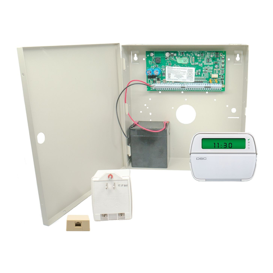
OUT Of THE BOX
Qty 1 K
Cabinet
Qty 1 K
PC Module
Qty 1 K
Installation guide
Qty 1 K
User manual
Qty 2 K
Cabinet Label
Qty 1 K
Cabinet Door Plug
Qty 4 K
Standoffs
Qty 16 K
5.6KΩ Resistors
Qty 1 K
2.2KΩ Resistors
Qty 1 K
1.0KΩ Resistors
Qty 1 K
10Ω Resistors
Qty 1 K
Grounding Kit
SPECIFICATIONS
Temp Range ....... 0°C-49°C (32°F-120°F)
Humidity (Max)........................... 93%R.H.
Power Supply........ 16.5V
/40VA @60Hz
AC
Current Draw (Panel) .........110mA (nom.)
Aux+ Output............11.1-12.6V
Bell Output ..............11.1-12.6V
Keypads (
Backward compatible with all PowerSeries keypads)
PK5500 Keypad...........................................................125mA (max.)
PK5501 Keypad...........................................................125mA (max.)
PK5508 LED Keypad...................................................125mA (max.)
PK5516 LED Keypad...................................................125mA (max.)
PC5532Z LED Keypad ................................................125mA (max.)
LCD5511 Fixed Message LCD Keypad........................ 85mA (max.)
LED5511Z 8-zone LED Keypad .................................100mA (max.)
PC5003C ..................................... 222x298x78mm (11.3x11.7x3.0in)
PC500C ......................................... 213x235x78mm (8.4x9.25x3.0in)
Refer to the Reference Manual for alternate control cabinets
FEATURES
On-board Zones
Hardwired Zones
Wireless Zones
Keypad Zone Support
On-board PGM Outputs
PGM Expansion
Keypads
Partitions
User Codes
Event Buffer
Transformer Required
Battery Required
/700mA
Bell Output
DC
/700mA
DC
COMPATIBLE DEVICES
Cabinets
Classified in Accordance with ANSI/SIA CP-01-2000 (SIA-FAR)
PC1616
6
8
16 (1xPC5108)
32(3xPC5108)
16
32
PGM 1 - 50mA
PGM 1 - 50mA
PGM 2 - 300mA
PGM 2 - 300mA
8x50mA (PC5208)
8x50mA (PC5208)
4x500 mA (PC5204)
4x500 mA (PC5204)
8
8
2
4
32 + Master Codes
32 + Master Codes
500 Events
500 Events
16.5V
/40VA
16.5V
AC
4Ah / 7Ah/14AHr
4Ah / 7Ah/14AHr
12V/700 mA (cont)
12V/700 mA (cont)
T-Link TL-250/TL300 .......................................................275/350mA
PC5100 2-wire Interface ............ 40mA plus devices to 170mA max.
PC5132-433 Wireless Receiver .............................................125mA
RF5108-433 Wireless Receiver .............................................125mA
PC5108 Zone Expander ..........................................................30mA
PC5204 Power Supply with 4 Programmable Outputs ............30mA
PC5208 Low Current Programmable Output Module ..............50mA
PC5400 Printer/DVAC Module .................................................65mA
PC5401 Bi-Directional RS232 Module (Not UL Listed) ............65mA
Escort5580 Telephone Interface Module ...............................130mA
Refer to the Reference Manual for additional devices.
PC1832
PC1864
8
64 (7xPC5108)
32
PGM 1, 3, 4 - 50mA
PGM 2 - 300mA
8x50mA (PC5208)
4x500 mA (PC5204)
8
8
32 + Master Codes
500 Events
/40VA
16.5V
/40VA
AC
AC
4Ah / 7Ah/14AHr
12V/700 mA (cont)
Modules
2 9 0 0 7 1 0 9 R0 0 3
Advertisement
Table of Contents
Troubleshooting

Related Manuals for DSC POWERSERIES PC1616


Summary of Contents for DSC POWERSERIES PC1616
- Page 1 This Installation Guide provides the basic installation, wiring and programming information required to program the PowerSeries PC1616, PC1832 and PC1864 control panels. This guide shall be used in conjunction with the PowerSeries PC1616/1832/1864 Reference Manual which can be obtained from your local dealer or downloaded from the DSC web site at www.dsc.com.
-
Page 2: Hardware Installation
Violated 3. Bell Wiring These terminals supply 700mA of current at 12V installations and 11.1-12.6 V for residential installations (e.g.DSC SD-15 WULF). To comply with NFPA 72 Temporal Three Pattern requirements: Program Section [013] Opt [8] ON. The Bell output is supervised and power limited. If unused, connect a 1000Ω... - Page 3 Z7 COM Z8 EGND AUX- BELL- PGM2 PGM4 See Section 9 for ground wiring details 12V / 7 AHr 12V / 7 AHr BLACK DSC Model BD7-12 or equivalent Battery StandbyTime: 24Hrs min. UA503 REV XX PC1616/1832/1864 PC-LINK Internally Connected PC1864...
-
Page 4: Aux Power Wiring
4. AUX Power Wiring The control panel can provide a maximum of 700mA of current for modules, powered detectors, relays, LED’s etc.… If the total current required exceeds 700mA an additional power supply is required (e.g.,PC5200, PC5204). See list below. NOTE: Min/max operating voltages for devices, sensors and modules is 9.5V Refer to the list of Compatible Devices on the first page for the current draw of individual devices 5. -
Page 5: Testing And Troubleshooting
TESTING & TROUBLESHOOTING Testing: • Power up system • Program options as required (See Programming Section on reverse side) Note: For advanced programming refer to the PC1616/1832/1864 Reference manual • Violate, then restore zones • Verify correct Reporting Codes are sent to the Central Station Troubleshooting: LCD5500 LCD Programmable-Message Keypad •... -
Page 6: Troubleshooting
Trouble Trouble [1] Service Required [1] Low Battery [2] Bell Circuit [3] General System Trouble [4] General System Tamper [5] Module Supervision [6] RF Jam Detected [7] PC5204 Low Battery [8] PC5204 AC Failure Cause Press [1] to determine specific trouble Main panel battery less than 11 V NOTE: This trouble condition will not clear until the battery voltage is... - Page 7 Trouble Trouble [2] AC Failure Trouble [3] Telephone Line Trouble Trouble [4] Failure to Communicate Trouble [5] Zone Fault Cause No AC at panel AC input terminals Phone Line Voltage at TIP, RING on main panel less than 3V Panel fails to communicate one or more events to central station Press [5] to determine specific zones with a fault trouble Open circuit is present on one or...
- Page 8 Trouble Trouble [5] Zone Fault (Cont.) Trouble [6] Zone Tamper Trouble [7] Wireless Device Low Battery 1st press – Wireless Zones 2nd press – Handheld Keypads 3rd press – Wireless Keys Trouble [8] Loss of Clock/Date Ensure you have the following information available before contacting Customer Support - Control Panel Type and Version, (e.g., PC1864 v4.1) NOTE: Version number can be accessed by entering [ also located on a sticker on the Printed Circuit Board.
-
Page 9: Keypad Codes
How to Program: DSC recommends filling in the Programming Worksheet with the required programming information before programming the system. This will reduce the time required to program and will help eliminate errors. To enter Installer Programming press [*][8][5555]. The Program light will FLASH (or in the case of the programmable LCD keypad the display will change to ‘Enter Section’). - Page 10 [402] Downloading Computer Phone Number (32-digits) II___II___II___II___II___II___II___II___II___II___II___II___II___II___II___I I___II___II___II___II___II___II___II___II___II___II___II___II___II___II___II___I [403] Downloading Access Code Enter 4 or 6-digit code This code identifies the downloading computer to the panel. The downloading access code prevents unauthorized access to the panel. This code must match the code programmed in the downloading file before the panel will allow remote or local DLS connection.
- Page 11 [005] System Times This section programs the entry and exit delays for the control panel. After entering section [005] press [1] to select partition 1. Enter the 3-digit delay time for Delay 1 type zones, Delay 2 type zones followed by the exit delay time. Press [#] to exit the sub-menu and return to regular programming.
- Page 12 NOTE:If the automatic SIA or automatic Contact ID reporting formats are not used, reporting codes must be programmed. To program reporting codes refer to the PowerSeries PC1616/1832/1864 Refer- ence Manual which can be downloaded from the DSC web site at www.dsc.com [382] – Third Communicator Option Codes The 4th toggle option in this section is used to enable/disable Call Waiting Cancel.
-
Page 13: Listing Requirements
•The installation must have a bell which is UL Listed for mercantile local alarms (AMSECO MBL10B with model AB-12 bell housing). •The digital communicator must be enabled. •The control panel must be in the attack resistant enclosure (DSC Model CMC-1 or PC4050CAR). Grade C Central Station •The digital communicator must be enabled. -
Page 14: Programming Section
PC1616/PC1832/PC1864 Installer Programming Quick Reference Chart SIA False Alarm Reduction SIA Feature Programming Section Exit Time Access to Entry and Exit delays for each partition and Bell Time Out for the system [005], 3rd entry Progress Annunciation/ Enables audible exit beeps from the keypad for the duration of exit delay Disable - for Silent Exit [014], Option 6 ON Exit Time Restart... -
Page 15: Note To Installers
The Customer assumes all responsibility for the proper selection, installation, operation and maintenance of any products purchased from DSC. Custom products are only warranted to the extent that they do not function upon delivery. In such cases, DSC can replace or credit at its option. -
Page 16: Fcc Compliance Statement
Telephone Company may request that you disconnect the equipment until the problem is solved. This equipment is of a type that is not intended to be repaired by the end user. DSC c/o APL Logistics, 757 Douglas Hill Rd., Lithia Springs, GA 30122 Additional Information Connection to party line service is subject to state tariffs.
Need help?
Do you have a question about the POWERSERIES PC1616 and is the answer not in the manual?
Questions and answers