Advertisement
Quick Links
Read this instructions carefully before use
Minoura Japan Headquarters
(for all customers)
1197-1 Godo, Anpachi, Gifu 503-2305 Japan
Phone: +81-584-27-3131 / Fax: +81-584-27-7505
Email: minoura@minoura.jp
www.minoura.jp
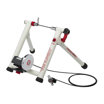
Indoor Bicycle Trainer – instructions manual
V150
Minoura North American Tech Center
1996 East Avenue, Hayward, CA 94541 U.S.A.
Phone: 1-510-538-8599 / Fax: 1-510-538-5899
Email: support@minourausa.com
Made in Japan
Applicable Tire Size Capacity
• Wtihout Z-Adaptor: 26x1.5 - 700x40c
• With Z-Adaptor: 22x1-3/8 - 26x1.25
(for U.S. residents only)
-2
(ver.1.2 2010/3)
Advertisement

Related Manuals for MINOURA V150-2 - V1.2 3-2010


Summary of Contents for MINOURA V150-2 - V1.2 3-2010
- Page 1 V150 Indoor Bicycle Trainer – instructions manual (ver.1.2 2010/3) Applicable Tire Size Capacity • Wtihout Z-Adaptor: 26x1.5 - 700x40c • With Z-Adaptor: 22x1-3/8 - 26x1.25 Read this instructions carefully before use Minoura Japan Headquarters Minoura North American Tech Center (for all customers) (for U.S. residents only) 1197-1 Godo, Anpachi, Gifu 503-2305 Japan 1996 East Avenue, Hayward, CA 94541 U.S.A. Phone: +81-584-27-3131 / Fax: +81-584-27-7505 Phone: 1-510-538-8599 / Fax: 1-510-538-5899 Email: minoura@minoura.jp Email: support@minourausa.com www.minoura.jp Made in Japan...
-
Page 2: Important Notice
Tools are not supplied in the kit. • Use the supplied rear quick release skewer for maximum stability. Minoura is not responsible for any problem caused from using your own skewer. • Use on flat and level floor or ground for your safety. - Page 3 V150-2 Schematics UF-9 UF-6 UF-7 UF-8 UF-17 GM-20 M8-4 UF-13 GM-4 UF-13 GM-9 GM-7 GM-10 GM-6 GM-11 GM-5 GM-12 GM-3 GM-2 GM-13 GM-16 GM-14 GM-15 UF-6: Right Side Coupling & Clamp Lever GM-6: Drive Roller, Axle & Bearing UF-7: Clamp Lever Guide GM-7: Drive Roller Holder UF-8: Left Side Coupling GM-9: Axle End Cap UF-9: Coupling Lock Ring (Red) GM-10: Mag Unit Fitting Bracket UF-13: Rubber Cap (45mm) GM-11: Rubber Shim UF-17: V150-2 Main Frame (White)
- Page 4 Replace your rear wheel quick release skewer to the supplied one. Minoura guarantees the stability only when using the supplied skewer due to the coupling inner shape. If your bike is not equipped with quick release skewer and it's a hub nut type, replace the left side coupling (UF-8) to the optional "Left Side Coupling for Hub...
- Page 5 Place your rear wheel in between the couplings. 1) Loosen the lock ring (UF-9) to allow the left side coupling (UF-8) be free. (see Fig. C) (Fig. C) 2) Pull up the quick hub clamp lever (UF-6) to retract the right side coupling. (see Fig. D) (Fig. D) 3) Insert the left side (quick lever side) skewer into the left side coupling first.
- Page 6 Contact the Drive Roller to the rear tire with the following steps; 1) Pull up the Foot Pedal to release the Mag unit lock. (see Fig. J) 2) Turn the Micro Adjust Knob clockwise until the roller comes close to the rear tire 2 - 3 mm. (see Fig. K) Do not make the roller touch the tire.
- Page 7 If the rear tire has touched any other parts than the Drive Roller, the part may be damaged and your tire will wear out quickly. It is impossible to adjust the rear wheel position by adjusting the left side coupling position.
- Page 8 Why My Remote Shifter Doesn't Work Properly? You may have a shifting problem that you cannot set at L or H position properly due to the lengthened inner cable. To fix this problem, follow the steps to adjust the initial cable tension. Set your remote shifter at "H"...
Need help?
Do you have a question about the V150-2 - V1.2 3-2010 and is the answer not in the manual?
Questions and answers