Intel D945GCLF Product Manual
Hide thumbs
Also See for D945GCLF:
- Technical product specification (84 pages) ,
- Specification (8 pages)
Table of Contents
Advertisement
Advertisement
Table of Contents

Related Manuals for Intel D945GCLF


Summary of Contents for Intel D945GCLF
- Page 1 Intel® Desktop Board D945GCLF Product Guide Order Number: E35045-004...
-
Page 2: Revision History
Intel Corporation by going to the World Wide Web site at: http://www.intel.com/ or by calling 1-800-548-4725. Intel, the Intel logo, and Intel Atom are trademarks of Intel Corporation in the U. S. and other countries. * Other names and brands may be claimed as the property of others. -
Page 3: Intended Audience
The suitability of this product for other PC or embedded non-PC applications or other environments, such as medical, industrial, alarm systems, test equipment, etc. may not be supported without further evaluation by Intel. Document Organization The chapters in this Product Guide are arranged as follows:... - Page 4 Intel Desktop Board D945GCLF Product Guide Terminology The table below gives descriptions to some common terms used in the product guide. Term Description Gigabyte (1,073,741,824 bytes) Gigahertz (one billion hertz) Kilobyte (1024 bytes) Megabyte (1,048,576 bytes) Mbit Megabit (1,048,576 bits)
-
Page 5: Table Of Contents
Contents 1 Desktop Board Features Desktop Board Components.................10 Processor......................12 Main Memory.....................12 ® Intel 945GC Express Chipset ................13 Onboard Audio Subsystem ..................13 Input/Output (I/O) Controller ................14 LAN Subsystem ....................15 LAN Subsystem Software................15 LAN Status LEDs..................15 Hi-Speed USB 2.0 Support ..................16 Enhanced IDE Interface ..................16 Serial ATA......................16... - Page 6 Intel Desktop Board D945GCLF Product Guide Connecting Power Supply Cables ................33 Setting the BIOS Configuration Jumper ..............34 Clearing Passwords ..................35 Replacing the Battery ..................36 3 Updating the BIOS ® Updating the BIOS with the Intel Express BIOS Update Utility.........41 Updating the BIOS with the Iflash Memory Update Utility .........41 Obtaining the BIOS Update File ..............41...
- Page 7 1. Feature Summary..................9 2. Desktop Boards D945GCLF Components ............11 3. LAN Status LEDs ..................15 4. Front Panel Audio Header Signal Names for Intel High Definition Audio....31 5. Hi-Speed USB 2.0 Header Signal Names ............31 6. Front Panel Header Signal Names ..............32 7.
- Page 8 Intel Desktop Board D945GCLF Product Guide viii...
-
Page 9: Desktop Board Features
• Microsoft Windows Vista Home Basic 64-bit Edition • Microsoft Windows* XP Professional • Microsoft Windows XP Professional x64 Edition • Microsoft Windows XP Home For more information about Desktop Board D945GCLF, including the Technical Product Specification (TPS), BIOS updates, and device drivers, go to http://support.intel.com/support/motherboards/desktop/. -
Page 10: Desktop Board Components
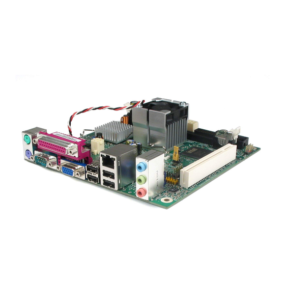
Intel Desktop Board D945GCLF Product Guide Desktop Board Components Figure 1 shows the location of the major components on Desktop Board D945GCLF. Figure 1. Intel Desktop Board D945GCLF Components... - Page 11 Desktop Board Features Table 2. Desktop Boards D945GCLF Components Label Description PCI bus add-in card connector Front panel audio header Back panel connectors 12 V processor core voltage connector (2 x 2) Rear fan (3-pin) header Processor DDR 2 DIMM connector...
-
Page 12: Processor
Desktop Board may result in damage to the board, or the system may not function properly. Desktop Board D945GCLF includes an Intel Atom processor 230. The processor is soldered to the Desktop Board and is not customer upgradeable. -
Page 13: Intel 945Gc Express Chipset
The ICH7 is a centralized controller for the board’s I/O paths. For more information about the Intel 945GC Express Chipset, go to http://www.intel.com/design/chipsets/express_flyer.htm. Onboard Audio Subsystem Desktop Board D945GCLF has a 4-channel (two independent 2-channel audio streams) onboard audio subsystem that includes a Realtek ALC662 audio codec. The audio subsystem features: •... -
Page 14: Input/Output (I/O) Controller
Intel Desktop Board D945GCLF Product Guide Figure 2 shows the default assignment of the back panel audio connectors. Item Description Line In Line Out Mic In Figure 2. Back Panel Audio Connectors NOTE The back panel audio line out connector is designed to power headphones or amplified speakers only. -
Page 15: Lan Subsystem
Programmable transit threshold • Configurable EEPROM that contains the MAC address LAN Subsystem Software For LAN software and drivers, refer to the D945GCLF link on Intel’s World Wide Web site at http://support.intel.com/support/motherboards/desktop. LAN Status LEDs Two LEDs are built into the RJ-45 LAN connector located on the back panel (see Figure 3). -
Page 16: Hi-Speed Usb 2.0 Support
Intel Desktop Board D945GCLF Product Guide Hi-Speed USB 2.0 Support NOTE Computer systems that have an unshielded cable attached to a USB port might not meet FCC Class B requirements, even if no device or a low-speed USB device is attached to the cable. -
Page 17: Bios
Desktop Board Features BIOS The BIOS provides the Power-On Self-Test (POST), the BIOS Setup program, the PCI and IDE auto-configuration utilities, and the video BIOS. IDE Auto Configuration If you install an IDE device (such as a hard drive) in your computer, the auto- configuration utility in the BIOS automatically detects and configures the device for your computer. -
Page 18: Power Management Features
Intel Desktop Board D945GCLF Product Guide Power Management Features Power management is implemented at several levels, including: • Advanced Configuration and Power Interface (ACPI) • Hardware support: ― Power connectors ― Fan headers ― +5 V standby power indicator LED ―... -
Page 19: +5 V Standby Power Indicator Led
Figure 4. Location of the Standby Power Indicator For more information on standby current requirements for the Desktop Board, refer to the Technical Product Specification on the D945GCLF web page at: http://support.intel.com/support/motherboards/desktop/... -
Page 20: Lan Wake Capabilities
Intel Desktop Board D945GCLF Product Guide LAN Wake Capabilities CAUTION For LAN wake capabilities, the 5 V standby line for the power supply must be capable of delivering adequate +5 V standby current. Failure to provide adequate standby current when using this feature can damage the power supply. -
Page 21: Installing And Replacing Desktop Board Components
2 Installing and Replacing Desktop Board Components This chapter tells you how to: • Install the I/O shield • Install and remove the Desktop Board • Install and remove memory • Connect the IDE cable • Connect the SATA cable •... -
Page 22: Installation Precautions
Intel Desktop Board D945GCLF Product Guide Installation Precautions When you install and test the Intel Desktop Board, observe all warnings and cautions in the installation instructions. To avoid injury, be careful of: • Sharp pins on connectors or headers •... -
Page 23: Installing The I/O Shield
Installing and Replacing Desktop Board Components Installing the I/O Shield The Desktop Board comes with an I/O shield. When installed in the chassis, the shield blocks radio frequency transmissions, protects internal components from dust and foreign objects, and promotes correct airflow within the chassis. Install the I/O shield before installing the Desktop Board in the chassis. -
Page 24: Installing And Removing The Desktop Board
Refer to your chassis manual for instructions on installing and removing the Desktop Board. Figure 6 shows the location of the mounting screw holes for Desktop Board D945GCLF. Figure 6. Desktop Board D945GCLF Mounting Screw Holes... -
Page 25: Installing And Removing Memory
Installing and Replacing Desktop Board Components Installing and Removing Memory NOTE To be fully compliant with all applicable Intel SDRAM memory specifications, the boards require DIMMs that support the Serial Presence Detect (SPD) data structure. The Desktop Board has one 240-pin DDR2 DIMM socket. - Page 26 Intel Desktop Board D945GCLF Product Guide 1. Observe the precautions in "Before You Begin" on page 21. 2. Turn off all peripheral devices connected to the computer. Turn off the computer and disconnect the AC power cord. 3. Remove the computer’s cover and locate the DIMM socket (see Figure 8).
-
Page 27: Removing Dimms
For correct function of the cable: 1. Observe the precautions in "Before You Begin" on page 21. 2. Attach the cable end with the single connector (blue) to the Intel Desktop Board (Figure 9). 3. Attach the cable end with the two closely spaced connectors (gray and black) to... -
Page 28: Connecting The Ide Cable
Intel Desktop Board D945GCLF Product Guide Figure 9. Connecting the IDE Cable... -
Page 29: Connecting The Serial Ata (Sata) Cable
Installing and Replacing Desktop Board Components Connecting the Serial ATA (SATA) Cable The SATA cable supports the Serial ATA protocol and connects a single drive to the desktop board. For correct cable function: 1. Observe the precautions in "Before You Begin" on page 21. 2. -
Page 30: Connecting Internal Headers
Intel Desktop Board D945GCLF Product Guide Connecting Internal Headers Before connecting cables to the internal headers, observe the precautions in "Before You Begin" on page 21. Figure 11 shows the location of the board’s internal headers. Item Description Audio Hi-speed USB 2.0 Front panel Figure 11. -
Page 31: Front Panel Hd Audio Header
Front Panel HD Audio Header Figure 11, A shows the location of the front panel audio header. Table 4 shows the pin assignments for the front panel audio header. Table 4. Front Panel Audio Header Signal Names for Intel High Definition Audio Signal Name... -
Page 32: Connecting To The Front Panel Header
Intel Desktop Board D945GCLF Product Guide Connecting to the Front Panel Header Before connecting to the front panel header, observe the precautions in "Before You Begin" on page 21. See Figure 11, C on page 30 for the location of the front panel header. -
Page 33: Connecting Power Supply Cables
Installing and Replacing Desktop Board Components Connecting Power Supply Cables CAUTION Failure to use an appropriate power supply and/or not connecting the 12 V (2 x 2) power connector to the Desktop Board may result in damage to the board or the system may not function properly. -
Page 34: Setting The Bios Configuration Jumper
Intel Desktop Board D945GCLF Product Guide Setting the BIOS Configuration Jumper NOTE Always turn off the power and unplug the power cord from the computer before changing a jumper. Moving the jumper with the power on may result in unreliable computer operation. -
Page 35: Clearing Passwords
Installing and Replacing Desktop Board Components Figure 14 shows the location of the Desktop Board’s BIOS configuration jumper block. Table 7. Jumper Settings for the BIOS Setup Program Modes Jumper Setting Mode Description Normal (default) (1-2) The BIOS uses the current configuration and passwords for booting. -
Page 36: Replacing The Battery
Intel Desktop Board D945GCLF Product Guide 11. Remove the computer cover. 12. To restore normal operation, place the jumper on pins 1-2 as shown below. 13. Replace the cover, plug in the computer, and turn on the computer. Replacing the Battery A coin-cell battery (CR2032) powers the real-time clock and CMOS memory. - Page 37 Installing and Replacing Desktop Board Components VORSICHT Bei falschem Einsetzen einer neuen Batterie besteht Explosionsgefahr. Die Batterie darf nur durch denselben oder einen entsprechenden, vom Hersteller empfohlenen Batterietyp ersetzt werden. Entsorgen Sie ver- brauchte Batterien den Anweisungen des Herstellers entsprechend. AVVERTIMENTO Esiste il pericolo di un esplosione se la pila non viene sostituita in modo corretto.
- Page 38 Intel Desktop Board D945GCLF Product Guide AWAS Risiko letupan wujud jika bateri digantikan dengan jenis yang tidak betul. Bateri sepatutnya dikitar semula jika boleh. Pelupusan bateri terpakai mestilah mematuhi peraturan alam sekitar tempatan. OSTRZEŻENIE Istnieje niebezpieczeństwo wybuchu w przypadku zastosowania niewłaściwego typu baterii. Zużyte baterie należy w miarę...
- Page 39 Installing and Replacing Desktop Board Components OСТОРОГА Використовуйте батареї правильного типу, інакше існуватиме ризик вибуху. Якщо можливо, використані батареї слід утилізувати. Утилізація використаних батарей має бути виконана згідно місцевих норм, що регулюють охорону довкілля.
-
Page 40: Removing The Battery
Intel Desktop Board D945GCLF Product Guide To replace the battery, follow these steps: 1. Observe the precautions in "Before You Begin" (see page 21). 2. Turn off all peripheral devices connected to the computer. Disconnect the computer’s power cord from the AC power source (wall outlet or power adapter). -
Page 41: Updating The Bios
Power-On Self-Test (POST) memory test begins and before the operating system boot begins. This chapter tells you how to update the BIOS by either using the Intel Express BIOS Update utility or the Iflash Memory Update utility, and how to recover the BIOS if an update fails. -
Page 42: Updating The Bios With The Iflash Memory Update Utility
You can obtain either of these files through your computer supplier or by navigating to the Desktop Board D945GCLF page at http://support.intel.com/support/motherboards/desktop. Navigate to the D945GCLF page, click “[view] Latest BIOS updates,” and select the Iflash BIOS Update utility file. CAUTION Do not interrupt the process or the system may not function properly. -
Page 43: A Bios Error Messages
A BIOS Error Messages BIOS Front-panel Power LED Blink Codes The front-panel power LED is used by the BIOS to display messages. For example, the LED is on when the system is powered on, and blinks off for 0.5 second when processor initialization is complete. -
Page 44: Bios Error Messages
Intel Desktop Board D945GCLF Product Guide BIOS Error Messages Whenever a recoverable error occurs during POST, the BIOS displays an error message on the PC monitor that describes the problem. Table 10 lists the BIOS error messages and a brief description of each. -
Page 45: B Regulatory Compliance
Product Ecology statements • Electromagnetic Compatibility (EMC) regulations • Product certifications Safety Standards Desktop Board D945GCLF complies with the safety standards stated in Table 11 when correctly installed in a compatible host system. Table 11. Safety Standards Regulation Title CSA/UL 60950-1, First Information Technology Equipment –... -
Page 46: European Union Declaration Of Conformity Statement
European Union Declaration of Conformity Statement ® We, Intel Corporation, declare under our sole responsibility that the product Intel Desktop Board D945GCLF is in conformity with all applicable essential requirements necessary for CE marking, following the provisions of the European Council Directives 2004/108/EC (EMC Directive) and 2006/95/EC (Low Voltage Directive). -
Page 47: Product Ecology Statements
The following information is provided to address worldwide product ecology concerns and regulations. Recycling Considerations As part of its commitment to environmental responsibility, Intel has implemented the ® Intel Product Recycling Program to allow retail consumers of Intel’s branded products to return used products to selected locations for proper recycling. - Page 48 Français Dans le cadre de son engagement pour la protection de l'environnement, Intel a mis en œuvre le programme Intel Product Recycling Program (Programme de recyclage des produits Intel) pour permettre aux consommateurs de produits Intel de recycler les produits usés en les retournant à...
- Page 49 Regulatory Compliance Portuguese Como parte deste compromisso com o respeito ao ambiente, a Intel implementou o Programa de Reciclagem de Produtos para que os consumidores finais possam enviar produtos Intel usados para locais selecionados, onde esses produtos são reciclados de maneira adequada.
-
Page 50: Lead-Free 2Li/Pb-Free 2Li Board
FLI is acceptable because of the RoHS "flip chip" or "die bump" interconnect exemption. Desktop Board D945GCLF is a lead-free second level interconnect product. Table 12 shows the lead-free second level interconnect marks as they appear on the board and accompanying collateral. -
Page 51: Restriction Of Hazardous Substances (Rohs)
The EFUP for Intel Desktop Boards has been determined to be 10 years. The EFUP for Desktop Board D945GCLF is shown in Table 13. Table 13. China RoHS Environmentally Friendly Use Period Mark... -
Page 52: Desktop Board D945Gclf China Rohs Material Self Declaration Table
Intel Desktop Board D945GCLF Product Guide The China MII also stipulates that a material Self Declaration Table (SDT) must be included in a product’s user documentation. The SDT for Desktop Board D945GCLF is shown in Figure 16. Figure 16. Desktop Board D945GCLF China RoHS Material... -
Page 53: Emc Regulations
Regulatory Compliance EMC Regulations Desktop Board D945GCLF complies with the EMC regulations stated in Table 14 when correctly installed in a compatible host system. Table 14. EMC Regulations Regulation (Class B) Title FCC 47 CFR Part 15, Title 47 of the Code of Federal Regulations, Part 15, Subpart B, Subpart B Radio Frequency Devices. -
Page 54: Ensure Electromagnetic Compatibility (Emc) Compliance
Intel Desktop Board D945GCLF Product Guide Korean Class B statement translation: This is household equipment that is certified to comply with EMC requirements. You may use this equipment in residential environments and other non-residential environments. Ensure Electromagnetic Compatibility (EMC) Compliance... -
Page 55: Product Certifications
Regulatory Compliance Product Certifications Board-Level Certification Markings Desktop Board D945GCLF has the product certification markings shown in Table 15. Table 15. Product Certification Markings Description Mark UL joint US/Canada Recognized Component mark. Includes adjacent UL file number for Intel Desktop Boards: E210882. -
Page 56: Chassis And Component Certifications
Intel Desktop Board D945GCLF Product Guide Chassis and Component Certifications Ensure that the chassis and certain components; such as the power supply, peripheral drives, wiring, and cables; are components certified for the country or market where used. Agency certification marks on the product are proof of certification. Typical...
Need help?
Do you have a question about the D945GCLF and is the answer not in the manual?
Questions and answers