Table of Contents
Advertisement
Quick Links
Advertisement
Table of Contents
Troubleshooting

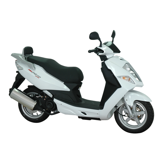
Summary of Contents for DAELIM S1 125
- Page 13 FRAME SERIAL NUMBER LOCATION ENGINE SERIAL NUMBER LOCATION ENGINE SERIAL NUMBER LOCATION FRAME SERIAL NUMBER LOCATION...
- Page 14 1,965mm 743mm 1,120mm 1,350mm 770mm 126mm 127kg 277kg 1.75 2.25 90/70 stroke SOHC 13.8 ATDC...
- Page 15 , 30A...
- Page 49 REAR VIEW MIRROR BATTERY FR. BRAKE LEVER BAG HOLDER MUFFLER TIRE REAR BRAKE DISK PILLION STEP...
- Page 53 (Intake pressure sensor+Intake temperature)
- Page 55 Starting and driving are temporary Unable MIL on continuously, when the engine operating Blink MIL blinks, when the main key is turn on (engine is stop)
- Page 56 INTAKE : MIL on/off INTAKE : MIL on intake intake The value of intake pressure is fixed as the INTAKE pressure just before when the intake pressure sensor is out of order. The value of intake temperature is fixed as a INTAKE temperature just before when the intake pressure sensor is out of order.
- Page 57 The wireharness to check the ECU Arrangement of ECU PI...
- Page 58 1.5 sec 3 sec 1 flashing cycle : 0.5 sec...
- Page 62 40 : INJECTOR control 39 : FUEL PUMP control INJECTOR FUEL PUMP RELAY...
- Page 65 The Fault code of intake pressure sensor The Fault code of intake temperature sensor Checking circuit MAPAT 3 : Inhalation pressure sensor GROUND 26 : 5V voltage 27 : IMP 28 : TBA...
- Page 68 Fault code number displayed by MIL Checking circuit 4 : SENSOR GROUND 18 : 5V SUPPLY VOLTAGE 19 : TPS...
- Page 70 PULL PULL PULL PULL PULL PULL PULL PULL PULL PULL PULL PULL PULL PULL...
- Page 71 CHECKING CIRCUIT 4 : SENSOR GROUND 20 : ETS...
- Page 72 Characters of ETS...
- Page 74 CHECKING CIRCUIT 33 : ISA CONTROL 39:FUEL PUMP FUEL PUMP RELAY...
- Page 77 CHECKING CIRCUIT OXYGEN SENSOR 2 : LAMBDA SENSOR GROUND 12 : OXYGEN SENSOR SIGNAL 34 : OXYGEN SENSOR HEATER...
- Page 79 CHECKING CIRCUIT 24 : MALFUNCTION INDICATOR LAMP OUTPUT MALFUNCTION INDICATOR LAMP(MIL)
- Page 82 Remove...
-
Page 128: Cylinder Head/Valve Parts Diagram
INJECTOR ASSY ENGINE TEMP.SENSOR... - Page 129 10-1 10-6 10-2 10-7 10-3 10-8 10-5 10-11 10-6 10-13...
- Page 143 throttle body...
- Page 145 11-1 11-3 11-1 11-5 11-2...
- Page 153 12-1 12-7 12-2 12-8 12-3 12-9 12-6 12-10...
- Page 165 13-1 13-7 13-2 13-7 13-3 13-10 13-4 13-12 13-5 13-14 13-6 13-19 FRONT 33.914~33.935mm 33.87mm 34~34.039mm 34.01mm FRONT REAR 25.278~25.328mm 25.27mm REAR 25.44~25.41mm 25.42mm 24.914~24.935mm 25.27mm FRONT COMBI BRAKE CALIPER PISTON O.D 25~25.039mm 25.07mm FRONT COMBI BRAKE CALIPER CYLINDER I.D...
- Page 187 14-1 14-5 14-2 14-7 14-3 14-7...
- Page 197 15-1 15-3 15-2 15-4 15-2 15-5...
- Page 198 14~15V 14~15V 13.5V...
- Page 203 16-1 16-6 16-3 16-6 16-4 16-5 0.73±0.08Ω(23℃±5℃) (15KΩ) 80~150...
- Page 205 pulser pulser...
- Page 206 The secondary coil resistance might not measure cause by the high voltage diode inside the ignition coil.
- Page 207 GREEN AND BLACK/WHITE GREEN AND BLACK/WHITE...
- Page 209 17-1 17-4 17-2 17-7 17-3...
- Page 217 18-1 18-4 18-1 18-2 18-2 18-3 18-3 18-4 18-4...
- Page 218 BAT 1 BAT 2 COLOR GRAY...
- Page 225 SERVICE MANUAL 2007. 04 PRINTED N N O O C C O O P P Y Y 2007. 04 PUBLICATION...
- Page 226 HEAD OFFICE(FACTORY) #58, SUNG SAN-DONG, CHANG WON, KYUNGNAM, KOREA TEL: (82-55) 239-7000 / FAX: (82-2) 467-9997...


Need help?
Do you have a question about the S1 125 and is the answer not in the manual?
Questions and answers