
Related Manuals for HP 347786-B21 - 8 Internal Port SAS HBA


Summary of Contents for HP 347786-B21 - 8 Internal Port SAS HBA
-
Page 1: Installation Guide
HP Eight-Port SAS/SATA RAID Host Bus Adapter Installation Guide June 2006 (Second edition) Part Number 377610-002... - Page 2 Legal notices © Copyright 2005, 2006 Hewlett-packard Development Company, L.P. The information contained herein is subject to change without notice. The only warranties for HP products and services are set forth in the express warranty statements accompanying such products and services. Nothing herein should be construed as constituting an additional warranty.
-
Page 3: Table Of Contents
Contents 1 Adapter features Connectors on the adapter board ......................4 Summary of specifications......................... 4 2 Installation procedure Preparing the server ..........................5 Installing the adapter hardware ......................... 5 Connecting the adapter to other devices ..................... 6 Completing the adapter installation procedure..................... 6 3 SAS BIOS configuration utility SAS BIOS features ........................... -
Page 4: Adapter Features
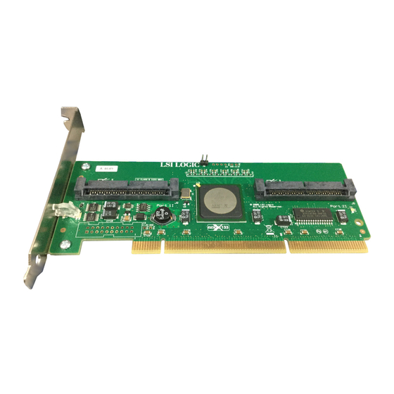
1 Adapter features Connectors on the adapter board Health LED (blinks green during normal operation, glows amber if HBA has failed) Port activity LED (blinks green during data transfer) Internal 4x SAS connector, port 1I Internal 4x SAS connector, port 2I Summary of specifications The HP Eight-Port SAS/SATA RAID Host Bus Adapter is a low-profile, 64-bit, 133-MHz PCI-X host bus adapter. -
Page 5: Installation Procedure
2 Installation procedure WARNING! To reduce the risk of personal injury or damage to the equipment, consult the safety information and user documentation provided with the server before attempting the installation. Many servers are capable of producing energy levels that are considered hazardous and are intended to be serviced only by qualified personnel who have been trained to deal with these hazards. -
Page 6: Connecting The Adapter To Other Devices
Connecting the adapter to other devices The cables that are required to connect the adapter to other devices are provided with most HP server products that need them. Table 1 lists some cables that can be used with this adapter. All HP cables are keyed so that they cannot be installed incorrectly. -
Page 7: Sas Bios Configuration Utility
3 SAS BIOS configuration utility SAS BIOS features The SAS BIOS is the bootable ROM code that manages SAS hardware resources. It is specific to a family of SAS controllers or processors. The SAS BIOS integrates with a standard system BIOS, extending the standard disk service routine provided through INT13h. -
Page 8: Configuration Utility Screens
Configuration utility screens All SAS BIOS configuration utility screens contain the following areas, starting at the top of the screen: Header area—Identifies the utility and version number. Menu area—Gives the title of the current screen. On screens other than the Adapter List screen, also identifies the adapter. -
Page 9: Global Properties Screen
Global Properties screen The Global Properties screen enables you to change the global scope settings. To access the Global Properties screen, press the Alt+N key combination while on the Adapter List screen. Table 2 Global properties field descriptions Field Description Pause when Boot This option specifies whether the BIOS pauses for user acknowledgement after displaying an alert Alert Displayed... -
Page 10: Adapter Properties Screen
Adapter Properties screen The Adapter Properties screen lists information about the adapter. From this screen, you can access other screens in the utility that enable you to perform RAID array configuration and management tasks or view information about the SAS topology of the adapter. To perform RAID array configuration and management tasks, move the cursor to the RAID Properties field and then press the Enter key. -
Page 11: Select New Array Type Screen
Select New Array Type screen This screen describes the types of RAID arrays that you can create, and enables you to select the type that you want to use. When you make your selection, the Create New Array screen opens. Create New Array screen The Create New Array screen enables you to select the disk drives for the new array. - Page 12 View Array screen The View Array screen displays the current array configuration and provides access to the array management screen. To view the next array, press the Alt+N key combination. To perform management tasks on this array, move the cursor to the Manage Array field and press the Enter key.
-
Page 13: Sas Topology Screen
SAS Topology screen The SAS Topology screen provides basic information about each device that is connected to the adapter. (To view all the information listed for a device, scroll horizontally.) This screen also provides a means for you to identify the physical device in the system that corresponds to a device in the list. To view detailed information about a device, move the cursor to the appropriate Device Identifier field and then press the Alt+D keys. - Page 14 Device Format screen This screen enables you to format a particular device. To access the Format screen, press the Enter key in the appropriate field on the Device Properties screen. To begin the format, press the F key. CAUTION: When you have started a format, you cannot pause or cancel it. NOTE: The formatting procedure sets the sector size to 512 bytes, even if the drive was previously formatted to another sector size.
-
Page 15: Exit Screen
The reassignment options are as follows: Yes—Reassign only this block. If another block must be reassigned in the future, display the prompt again. No—Do not reassign this block. If another block must be reassigned in the future, display the prompt again. All—Reassign the current block, and automatically reassign other blocks that must be reassigned, without displaying the prompt again. -
Page 16: Creating A Raid 1 Array
When selecting drives for the RAID 0 array, remember the following limitations: Every drive in the array must be of the same type, either SATA (with extended command set support) or SAS (with SMART support). Each drive must have 512-byte blocks. Drives with removable media are not supported. -
Page 17: Viewing Raid Array Properties
(Optional) To add a hot spare to the array, move the cursor to the Hot Spr column and press the + key, - key, or space bar. The drive that you select as the hot spare conforms to the same limitations as other drives in the array. -
Page 18: Locating A Disk Drive
To start a synchronization, select Synchronize Array on the Manage Array screen and then press the Y key. (To cancel a synchronization, press the N key.) Activating an array An array becomes inactive if, for example, it is removed from one controller or computer and moved to another one. -
Page 19: Electrostatic Discharge
4 Electrostatic discharge Preventing electrostatic discharge To prevent damaging the system, be aware of the precautions you must follow when setting up the system or handling parts. A discharge of static electricity from a finger or other conductor can damage system boards or other static-sensitive devices. -
Page 20: Regulatory Compliance Notices
EMC Directive 89/336/EEC Compliance with these directives implies conformity to applicable harmonized European standards (European Norms) which are listed on the EU Declaration of Conformity issued by Hewlett-Packard for this product or product family. This compliance is indicated by the following conformity marking placed on the product: This marking is valid for non-Telecom products and EU harmonized Telecom products (e.g., Bluetooth).