Table of Contents
Advertisement
®
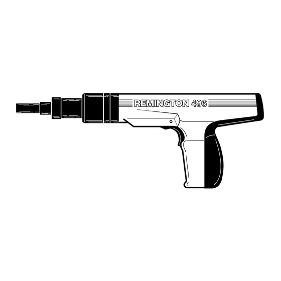
Power Pro
Semi-automatic
Model 496
™
®
POWDER ACTUATED TOOL
MANUFACTURERS´ INSTITUTE INC.
G 028
G 029
Operating
Instructions
482-1
Important:
Read this manual and all labels carefully before
operating your powder actuated tool. This manual
should always accompany the tool and be transferred
with it upon change of ownership.
Advertisement
Table of Contents

Related Manuals for Remington 496


Summary of Contents for Remington 496
-
Page 1: Operating Instructions
® Power Pro Semi-automatic Model 496 ™ ® POWDER ACTUATED TOOL MANUFACTURERS´ INSTITUTE INC. G 028 G 029 Operating Instructions 482-1 Important: Read this manual and all labels carefully before operating your powder actuated tool. This manual should always accompany the tool and be transferred... -
Page 2: Table Of Contents
Spall Shield Power Fastener† Assembly Muzzle/Guide Recommended Approved Goggles † Not supplied with tool INDEX REMINGTON Semi-automatic Model 496 Model 496 is designed for use with Maximum 3" Trigger Barrel 10-Shot Power Load Strip† 105635... -
Page 3: Warning: Safety Precautions
NOTE: The labor regulations of many states require that the operator of this tool on a job site be thoroughly trained and certified for competence prior to operating this tool. For certification procedures, call: DESA Tool Division, 1-800-626-2237 (USA) or 1-905-826-8010 (Canada). -
Page 4: Safety Precautions
Safety Precautions Always clear the work area on all sides and post appropriate warning signs on job sites. Make sure the work area is clean from loose material and debris. HANDLING THE TOOL G 018 Never place your hand over the muzzle. Accidental discharge can cause serious injury. - Page 5 G 018 Store powder actuated tool and power load strips in a locked container. Unload tool before storing. Keep power loads of different power levels in separate containers. G 018 Never carry or pass a loaded powder actuated tool. Never point a powder actuated tool at anyone.
- Page 6 Safety Precautions G 018 An operator taking medication should take extra precautions while handling the tool. Never drink alcoholic beverages or take medications which impair your vision, balance or judgement before using a powder actuated tool. KNOW YOUR FASTENING BASE MATERIAL 482-26 Point flattens...
- Page 7 CAST IRON GLASS G 018 Never attempt to drive power fasteners into very hard or brittle materials including, but not limited to cast iron, glass, tile, stone, brick, or hardened steel. Materials of this type tend to shatter and create hazard from flying particles. G 018 Never make fastenings in spalled or cracked areas.
- Page 8 Safety Precautions 3" 482-38 Do not drive power fasteners into concrete less than three times as thick as the intended fastener penetration, within 3" of the edge, within 3" of another power fastener or within 3" of a failed power fastener. WELD 482-40 TOO THIN...
- Page 9 Should the tool fail to fire, hold the muzzle firmly against the work surface for 30 seconds. Release the trigger and remove pressure on the tool while holding the muzzle against the work surface. Again press the tool firmly against the work surface and pull the trigger. If the tool still fails to fire, hold the tool firmly against the work surface for another 30 seconds before advancing the power load strip.
- Page 10 Always start with the lowest power level (green-level 3) and increase until a proper fastening is made (See page 13 Selecting Power Fasteners and Power Loads ). IMPORTANT: Purple (level 6) power load strips will not function in model 496 tool. G 018 Never use power loads in firearms.
- Page 11 G 018 482-59 Power fasteners are a permanently installed fixture. An act of demolition is required for their removal. Appropriate safety precautions must be taken. Head Shank Plastic Flute 482-60 Never use common nails or other materials as fasteners. Remington Power Fasteners are manufactured from special steel and heat treated to produce a very hard yet ductile fastener.
-
Page 12: Why A Power Fastener Holds
Why A Power Fastener Holds WHY A POWER FASTENER HOLDS IN CONCRETE The compression bond of the concrete to the power fastener accounts for the majority of the holding power. The fastener displaces the concrete which tries to return to its original form causing a squeezing effect. Maximum holding power is achieved when the depth of 482-64 penetration produces a bond on the power fastener equal... -
Page 13: Selecting Fasteners And Power Loads
Selecting Power Fasteners and Power loads FASTENING INTO CONCRETE The proper power fastener length can be determined by adding the thickness of the material to be fastened and the amount of fastener that will actually penetrate the con- crete. The concrete must be three times as thick as the intended fastener penetration. -
Page 14: Operation
Operation Grasp barrel assembly and slide forward rapidly until it stops. Push barrel assembly back into tool to the closed position. This sets piston into firing position. 482-70 Insert power fastener into muzzle of tool, head end first. Push the fastener until point is even with end of tool. - Page 15 Squeeze trigger to set power fastener. Be sure to keep pressure on tool during this operation. Grasp muzzle cap and slide barrel forward rapidly until it stops. Push barrel assembly back into tool to the closed position. This advances the power load strip and resets the piston for the next fastening.
-
Page 16: Parts List
Parts List Part 502001 502100 501104 301013 501106 501107 301014 502200 502202 501212 502215 TA4086 501300 501317 301047 501319 501320 501321 501422 501423 301531 301533 501526 502600 501733 501700 501500 101320-02 056486 IMPORTANT: Do not use key numbers when ordering service parts. Always order components by part number and description. -
Page 17: Assembly
Parts List Cleaning and Maintenance Clean tool after each days use. Disassemble and clean the barrel assembly with the wire brush provided with tool. Notice: Do not attempt to clean power load strip channel with wire brush. Apply good quality penetrating lubricant spray (such as WD-40) sparingly and wipe dry. -
Page 18: Barrel
Tool Disassembly WARNING: Always unload a powder actuated tool before disassembling, replacing barrel, cleaning, or assembling. A. REMOVING BARREL ASSEMBLY 1. Using screwdriver, lift end of annular spring and rotate spring until stop is uncovered (see Figure 1). Figure 1 - Rotating Annular Spring to Uncover Stop 2. - Page 19 6. Remove piston assembly from barrel (see Figure 4). Piston Assembly Figure 4 - Removing Piston Assembly from Barrel B. REMOVING REAR PAD AND HANDLE PAD ASSEMBLY 1. Loosen screws on back of handle pad assembly and rear pad with 3mm Allen wrench.
- Page 20 D. REMOVING FIRING PIN 1. Remove two springs from outer liner assembly (see Figure 8). 2. Push in sear and pull out firing pin guide (see Figure 8). Line up sear with end of slot. Remove spring and sear. Remove firing pin assembly. Remove push pin (see Figure 9).
-
Page 21: Tool Assembly
WARNING: Always unload a powder actuated tool before disassembling, replacing barrel, cleaning, or assembling. A. INSERTING OUTER LINER ASSEMBLY INTO HOUSING 1. Place ball bearing and spring in end of outer liner assembly (see Figure 11, page 20). 2. Slide outer liner assembly into tool body. B. - Page 22 E. ATTACHING REAR PAD AND HANDLE PAD ASSEMBLY 1. Replace the handle pad assembly. Tighten screw with 3mm Allen wrench. 2. Replace the rear pad with two screws provided. The screws will also secure the outer liner replaced in step A. Inserting Outer Liner Assembly into Housing (see Figure 16).
- Page 23 5. Insert stop into slot on outer liner assembly (see Figure 19). Stop Outer Liner Assembly Figure 19 - Replacing Stop 6. Push stop towards front of tool (see Figure 20). Stop Figure 20 - Pushing Stop towards Front of Tool 7.
-
Page 24: Barrel
Troubleshooting Guide PROBLEM Piston hangs out of muzzle. Overdriven fastener. Piston jammed. Power load strip will not advance. Reduction or loss of power. Tool does not completely depress. Tool does not fire. Opening and clos- ing of barrel or pushing down on tool, etc. -
Page 25: Parts Centrals
Contact authorized dealers of this product. If they can’t supply original replace- ment part(s), either contact your nearest Parts Central (see below) or call DESA International’s Parts Department at 1-800-972-7879for information. When calling DESA International, have ready • model number of your tool... -
Page 26: Remington
Application Chart Power load and power fastener application information. For fastening this Two by Fours Furring Strips Electrical Junction Boxes Conduit Clips Shelf Brackets 1/4" Plywood or Pegboard Power load listings are recommendations only. If you are in doubt, try a test fastening using the next lightest power load. -
Page 27: Maintenance Log
Maintenance Log Date Maintenance Performed 105635... -
Page 28: Limited Warranty Agreement
If within one (1) year from the purchase date this Powder Actuated Tool fails due to a defect in material or workmanship, DESA will send replacement part(s) or replace the tool at DESA’s option. To obtain service under this warranty, contact DESA at the number/address listed below. You must have the Serial Number, Model Number, date of purchase, and indicate the type of problem being experienced.
Need help?
Do you have a question about the 496 and is the answer not in the manual?
Questions and answers