Table of Contents
Advertisement
Advertisement
Table of Contents

Related Manuals for CEN-TECH 99722

Summary of Contents for CEN-TECH 99722
-
Page 2: Table Of Contents
Table of Contents Safety Precautions and Warnings........... 1 General Information ................ 2 On-Board Diagnostics (OBD) II........... 2 Diagnostic Trouble Codes (DTCs) ........2 Location of the Data Link Connector (DLC) ...... 3 OBD II Readiness Monitors ..........4 OBD II Monitor Readiness Status ........5 OBD II Definitions.............. -
Page 3: Safety Precautions And Warnings
1. Safety Precautions and Warnings To prevent personal injury or damage to vehicles and/or the scan tool, read this instruction manual first and observe the following safety precautions at a minimum whenever working on a vehicle: Always perform automotive testing in a safe environment. Wear safety eye protection that meets ANSI standards. -
Page 4: General Information
2. General Information 2.1 On-Board Diagnostics (OBD) II The first generation of On-Board Diagnostics (called OBD I) was developed by the California Air Resources Board (ARB) and implemented in 1988 to monitor some of the emission control components on vehicles. As technology evolved and the desire to improve the On-Board Diagnostic system increased, a new generation of On-Board Diagnostic system was developed. -
Page 5: Location Of The Data Link Connector (Dlc)
DTC Example P 0 2 0 2 Systems B=Body Identifying specific C=Chassis malfunctioning P=Powertrain section of the U=Network systems Sub-systems Code Type 1= Fuel and Air Metering Generic (SAE): P0, P2, P34-P39 2= Fuel and Air Metering B0, B3 3= Ignition System or Engine Misfire C0, C3 4= Auxiliary Emission Controls U0, U3. -
Page 6: Obd Ii Readiness Monitors
2.4 OBD II Readiness Monitors An important part of a vehicle’s OBD II system is the Readiness Monitors, which are indicators used to find out if all of the emissions components have been evaluated by the OBD II system. They are running periodic tests on specific systems and components to ensure that they are performing within allowable limits. -
Page 7: Obd Ii Monitor Readiness Status
EGR System O2 Sensors Catalyst Evaporative System O2 Sensor Heater Secondary air Heated Catalyst A/C system 2.5 OBD II Monitor Readiness Status OBD II systems must indicate whether or not the vehicle’s PCM’s monitor system has completed testing on each component. Components that have been tested will be reported as “Ready”, or “Complete”, meaning they have been tested by the OBD II system. -
Page 8: Obd Ii Definitions
2.6 OBD II Definitions Powertrain Control Module (PCM) -- OBD II terminology for the on-board computer that controls engine and drive train. Malfunction Indicator Light (MIL) -- Malfunction Indicator Light (Service Engine Soon, Check Engine) is a term used for the light on the instrument panel. - Page 9 Freeze Frame Data -- When an emissions related fault occurs, the OBD II system not only sets a code but also records a snapshot of the vehicle operating parameters to help in identifying the problem. This set of values is referred to as Freeze Frame Data and may include important engine parameters such as engine RPM, vehicle speed, air flow, engine load, fuel pressure, fuel trim value, engine coolant temperature, ignition timing advance, or closed loop status.
-
Page 10: Using The Scan Tool
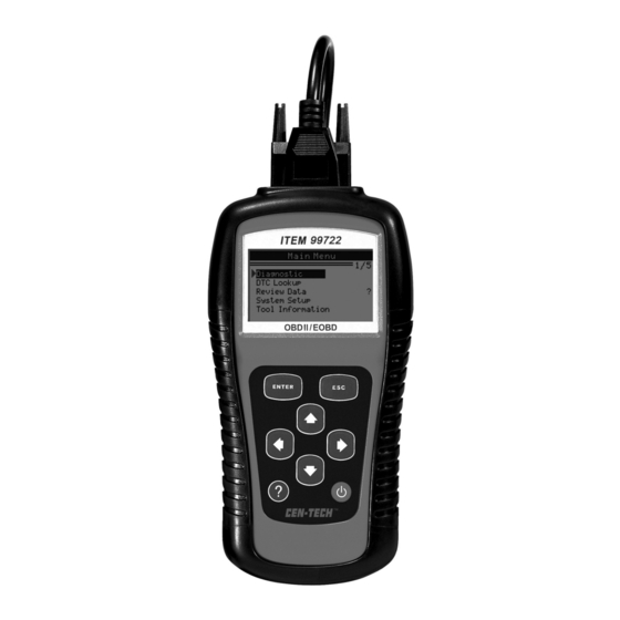
3. Using the Scan Tool 3.1 Tool Description... - Page 11 ① LCD DISPLAY -- Indicates test results. Backlit, 128 x 64 pixel display with contrast adjustment. ENTER BUTTON -- Confirms a selection (or action) from a ② menu. ESC BUTTON -- Cancels a selection (or action) from a menu ③ or returns to the menu.
-
Page 12: Specifications
3.2 Specifications Display: Backlit, 128 x 64 pixel display with contrast adjustment Operating Temperature: 0 to 60°C (32 to 140 F°) Storage Temperature: -20 to 70°C (-4 to 128 F°) External Power: 8.0 to 18.0 V power provided via vehicle battery Internal Power: 9V cell battery Dimensions: Length... -
Page 13: Keyboard
6) “ ” -- Indicates battery volume. 3.5 Keyboard No solvents such as alcohol are allowed to clean the keypad or display. Use a mild nonabrasive detergent and a soft cotton cloth. Do not soak the keypad as the keypad is not waterproof. 3.6 Power Internal Battery Power The scan tool has a 9V cell battery that provides power for off-car... - Page 14 Main Menu Diagnostics ►DTC Lookup Review Data System Setup Tool Information The number “x/x” to the right indicates total number of items under this menu and sequence of highlighted item. The “?” to the right indicates help information available. Press HELP button to view information for selected item.
-
Page 15: Product Setup
5) To enter another DTC, press ESC button to return to previous screen. 6) To exit to Main Menu, press ESC button. 3.8 Product Setup The scan tool allows you to make the following adjustments and settings: Language: Selects desired language. Contrast adjustment: Adjusts the contrast of the LCD display. - Page 16 Main Menu Diagnostics DTC Lookup Review Data ►System Setup Tool Information Language Setup • English is the default language. From System Setup menu, use UP/DOWN scroll button to select Language, and press ENTER button. System Setup Language ► Contrast Unit of Measure Auto Power-off Beep Set Tool Self-test...
- Page 17 Contrast Adjustment From System Setup menu, use UP/DOWN scroll button to select Contrast, and press ENTER button. System Setup Language Contrast ► Unit of Measure Auto Power-off Beep Set Tool Self-test From Contrast menu, use UP/DOWN scroll button to increase or decrease contrast.
- Page 18 System Setup Language Contrast Unit of Measure ► Auto Power-off Beep Set Tool Self-test From Unit of Measure menu, use UP/DOWN scroll button to select the desired unit of measurement. Unit of Measure English Metric ► Press ENTER button to save your selection and return to previous menu.
- Page 19 System Setup Language Contrast Unit of Measure Auto Power-off ► Beep Set Tool Self-test From Auto Power-off menu, use UP/DOWN scroll button to increase or decrease time. Auto Power-off Minute ] – Increase time ] – Decrease time [ENTER] - Confirm Press ENTER button to save your setting and return to previous menu.
- Page 20 From Beep Set menu, use UP/DOWN scroll button to select Beep ON or Beep OFF to turn on/off the beep. Beep Set Beep ON ►Beep OFF Press ENTER button to save your selection and return to previous menu. Tool Self-test The Tool Self-test function checks if the display and keyboard are working properly.
- Page 21 Tool Self-test Display Test ► Keyboard Test Press ENTER button again to start test. Look for missing spots in the solid black characters. When completed, press ESC button to return. Keyboard Test The Keyboard Test function verifies if the keys are working properly.
-
Page 22: Tool Information
Keyboard Test Press any key to start test Key: Double [ESC] to return If you press and hold the power switch, the key name does not show on the screen, but resets the scanner when powered by vehicle battery, or turns off the scanner when powered by cell battery. -
Page 23: Battery Replacement
Reinstall battery cover by sliding battery cover on and installing screw. 3.11 Vehicle Coverage ITEM 99722 OBDII/EOBD Scanner is specially designed to work with all OBD II compliant vehicles, including those equipped with next-generation protocol -- Control Area Network (CAN). It is... -
Page 24: Product Troubleshooting
For your vehicle to be OBD II compliant it must have a 16-pin DLC (Data Link Connector) under the dash and the Vehicle Emission Control Information Label must state that the vehicle is OBD II compliant. 3.12 Product Troubleshooting Vehicle Linking Error A communication error occurs if the scan tool fails to communicate with the vehicle’s ECU (Engine Control Unit). -
Page 25: Review Data
Check vehicle battery to make sure it is still good with at least 8.0 volts. 4. Review Data The Review Data function allows viewing of recorded data from last vehicle test. Use UP/DOWN scroll button to select Review Data from Main Menu, and press ENTER button Main Menu Diagnostics... -
Page 26: Obd Ii Diagnostics
P0118 Generic Engine Coolant Temperature Sensor 1 Circuit High 5. OBD II Diagnostics When more than one vehicle control module is detected by the scan tool, you will be prompted to select the module where the data may be retrieved. The most often to be selected are the Powertrain Control Module [PCM] and Transmission Control Module [TCM]. - Page 27 If the scan tool fails to communicate with the vehicle’s ECU (Engine Control Unit), a “LINKING ERROR!” message shows up on the display. Verify that the ignition is ON; Check if the scan tool’s OBD II connector is securely connected to the vehicle’s DLC; Verify that the vehicle is OBD2 compliant;...
-
Page 28: Reading Codes
System Status MIL Status Codes Found Readiness Complete Freeze Data Exist Press any key to con. If more than one module is detected, you will be prompted to select a module before testing. Control Module Engine ► Module $A4 Use UP/DOWN scroll button to select a module and press ENTER button. - Page 29 1) Use UP/DOWN scroll button to select Read Codes from Diagnostic Menu and press ENTER button. Diagnostic Menu Read Codes ► Erase Codes View Freeze Frame I/M Readiness Vehicle Info. Unit of Measure Use UP/DOWN scroll button to select Stored Codes or Pending Codes from the Trouble Codes menu and press ENTER button.
-
Page 30: Erasing Codes
The control module number, sequence of the DTCs, total number of codes detected and type of codes (Generic or Manufacturer specific) will be observed on the upper right hand corner of the display. If more than one DTC is found, use UP/DOWN scroll button, as necessary, until all the codes have been shown up. - Page 31 1) Use UP/DOWN scroll buttons to select Erase Codes from Diagnostics Menu and press ENTER button. Diagnostic Menu ► Read Codes Erase Codes View Freeze Frame I/M Readiness Vehicle Info. Unit of Measure 2) A warning message comes up asking for your confirmation. Erase Codes Erase trouble codes! Are you sure?
-
Page 32: Viewing Freeze Frame Data
Erase Codes Erase Done! Press any key to con. If the codes are not cleared, then an “Erase Failure. Turn Key on with Engine off!” message appears. Erase Codes Erase Failure. Turn Key on with Engine Off! Press any key to con. Press any button to return to Diagnostic Menu. - Page 33 ….………View Freeze Frame… ……… Reading PID.01 - Please Wait - If the retrieved information covers more than one screen, then a down arrow will appear. Use DOWN scroll button, as necessary, until all the data have been shown up. …………View Freeze Frame……...
-
Page 34: Retrieving I/M Readiness Status
5.4 Retrieving I/M Readiness Status I/M Readiness function is used to check the operations of the Emission System on OBD2 compliant vehicles. It is an excellent function to use prior to having a vehicle inspected for compliance to a state emissions program. Some latest vehicle models may support two types of I/M Readiness tests: A. - Page 35 ……………..I/M Readiness … Reading PID… - Please Wait - If the vehicle supports both types of tests, then both types will be shown on the screen for selection. ……………I/M Readiness………………. ► Since DTCs Cleared This Drive Cycle 4) Use UP/DOWN scroll button, as necessary, to view the status of the MIL light (“ON”...
-
Page 36: Viewing Vehicle Information
…………Since DTCs Cleared… ……… MIL Status Misfire Monitor Fuel System Mon Comp. Component Catalyst Mon Htd Catalyst 5) If the vehicle supports readiness test of “This Drive Cycle”, a screen of the following displays: …………..This Drive Cycle…… ………. MIL Status Misfire Monitor Fuel System Mon Comp. - Page 37 ..Diagnostic Menu..... Read Codes Erase Codes View Freeze Frame I/M Readiness Vehicle Info. ► Unit of Measure 2) Observe on-screen instruction. Vehicle Info. Turn key on with engine off ! Press any key to con. 3) Wait a few seconds while the scan tool reads vehicle information. ………………Vehicle Info.
- Page 38 ……………..Vehicle Info. Vehicle ID Number ►Calibration ID Cal. Verif. Number 5) View the vehicle information retrieved. ……………Calibration ID……………….. Cal ID1: LMC720……….. 6) Press ESC button to return previous menu.
-
Page 39: Appendix
6. Appendix 6.1 Appendix 1-- PID List PID Abbreviation Full Name DTC_CNT DTC Stored Number DTCFRZF FUELSYS1 Fuel System 1 Status FUELSYS2 Fuel System 2 Status LOAD_PCT (%) Calculated Load Value ETC(°F) Engine Coolant Temperature ETC(°C) Engine Coolant Temperature SHRTFT1 (%) Short Term Fuel Trim-Bank1 SHRTFT3 (%) Short Term Fuel Trim-Bank3... - Page 40 PID Abbreviation Full Name TP (%) Absolute Throttle Position AIR_STAT Commanded Secondary Air Status O2SLOC Location of O2 Sensors O2B1S1(V) O2 Sensor Output Voltage(B1S1) SHRTFTB1S1 (%) Short Term Fuel Trim(B1S1) O2B1S2(V) O2 Sensor Output Voltage(B1S2) SHRTFTB1S2 (%) Short Term Fuel Trim(B1S2) O2B1S3(V) O2 Sensor Output Voltage(B1S3) SHRTFTB1S3 (%)
- Page 41 PID Abbreviation Full Name O2B4S1(V) O2 Sensor Output Voltage(B4S1) SHRTFTB4S1 (%) Short Term Fuel Trim(B4S1) O2B4S2(V) O2 Sensor Output Voltage(B4S2) SHRTFTB4S2 (%) Short Term Fuel Trim(B4S2) OBDSUP OBD Require To Which Vehicle Designed O2SLOC Location of O2 Sensors RUNTM(sec) Time Since Engine Start MIL_DIST(km) Distance Traveled While MIL Activated MIL_DIST(mile)
- Page 42 PID Abbreviation Full Name O2B1S1(V) O2 Sensor Voltage(wide range O2S)(B2S1) EQ_RATB1S2 Equivalence Ratio(wide range O2S)(B1S2) O2B1S2(V) O2 Sensor Voltage(wide range O2S)(B1S2) EQ_RATB2S1 Equivalence Ratio(wide range O2S)(B2S1) O2B2S1(V) O2 Sensor Voltage(wide range O2S)(B2S1) EQ_RATB2S2 Equivalence Ratio(wide range O2S)(B2S2) O2B2S2(V) O2 Sensor Voltage(wide range O2S)(B2S2) EQ_RATB3S1 Equivalence Ratio(wide range O2S)(B3S1) O2B3S1(V)
- Page 43 PID Abbreviation Full Name EQ_RAT13 Equivalence Ratio(wide range O2S)(B1S3) O2S13(mA) O2 Sensor Current(wide range O2S)(B1S3) EQ_RAT14 Equivalence Ratio(wide range O2S)(B1S4) O2S14(mA) O2 Sensor Current(wide range O2S)(B1S4) EQ_RAT21 Equivalence Ratio(wide range O2S)(B2S1) O2S21(mA) O2 Sensor Current(wide range O2S)(B2S1) EQ_RAT22 Equivalence Ratio(wide range O2S)(B2S2) O2S22(mA) O2 Sensor Current(wide range O2S)(B2S2) EQ_RAT23...
- Page 44 PID Abbreviation Full Name CATEMP21(°F) Catalyst Temperature Bank2Sensor1 CATEMP21(°C) Catalyst Temperature Bank2Sensor1 CATEMP12(°F) Catalyst Temperature Bank1Sensor2 CATEMP12(°C) Catalyst Temperature Bank1Sensor2 CATEMP22(°F) Catalyst Temperature Bank2Sensor2 CATEMP22(°C) Catalyst Temperature Bank2Sensor2 VPWR(V) Control Module Voltage LOAD_ABS (%) Absolute Load Value EQ_RAT Commanded Equivalence Ratio TP_R (%) Relative Throttle Position AAT(°F)
Need help?
Do you have a question about the 99722 and is the answer not in the manual?
Questions and answers