Table of Contents
Advertisement
Advertisement
Table of Contents

Related Manuals for HEIDENHAIN MANUALPLUS 4110


Summary of Contents for HEIDENHAIN MANUALPLUS 4110
- Page 1 User Training MANUALplus 4110 NC Software 507 807-xx 9/2004...
- Page 2 This manual is intended to improve your operation and programming of the MANUALplus 4110. By way of examples, the setup of the lathe, the description and measurement of tools, and the creation of cycle programs and ICP contours are explained step by step.
- Page 3 Basic Knowledge User Components System Operation Tool Management Tool Measurement Machine Setup Longitudinal Machining Example Surface Machining Example Recess Machining Example Simulation Program Execution...
-
Page 5: Axis Directions/Reference Points
Z axis with the spindle surface. The workpiece datum (W) is the origin of the workpiece coordinate system. As a rule, the workpiece datum is at the intersection of the Z axis with the end surface. HEIDENHAIN MANUALplus 4110 Basic Knowledge... - Page 6 Depending on the design of the lathe, the tool is either in front of or behind the workpiece. The MANUALplus 4110 detects the design of your machine, and takes the position of the X axis into account for the graphic support, the simulation and the machining of the workpiece.
-
Page 7: The Coordinate System
Angles entered for the C axis are referenced to the datum of the C axis. Accuracy Positions can be programmed to an accuracy of 1 µm (0.001 mm) or 0.001°. This is also the accuracy with which they are displayed. HEIDENHAIN MANUALplus 4110 Basic Knowledge... - Page 8 S. The radius of the tool tip on lathe tools causes inaccuracies when machining tapers, chamfers and radii. These inaccuracies are removed with the cutter radius compensation. A new path of traverse (the equidistant line) is calculated to compensate for this error. HEIDENHAIN MANUALplus 4110 Basic Knowledge...
- Page 9 You program the spindle speed directly. The spindle speed is independent of the diameter the tool is working on. Constant cutting speed You program the spindle speed indirectly. The MANUALplus 4110 changes the spindle speed depending on the diameter momentarily being worked on by the tool. This results in a constant cutting speed.
- Page 10 HEIDENHAIN MANUALplus 4110 Basic Knowledge...
- Page 11 Calls the main menu in the Machine and Organization modes of operation Process key Selects a mode of operation. (Prerequisite: the MANUALplus 4110 must be in the main menu) Backspace key Deletes the character to the left of the cursor...
- Page 12 (character, field, line, etc.) Page forward/ Shows the information on the Page back previous or next screen page Switches between two input windows Info key Calls the error information or PLC status display HEIDENHAIN MANUALplus 4110 User Components...
- Page 13 Menu selection, soft keys Menu selection (9-field box) The MANUALplus 4110 presents cycles, tools and functions in the Machine and Tool Management modes as a 9-field box. Each field of this symbol corresponds to the numerical key that is located at the same position on the control’s numerical keypad.
-
Page 14: Machine Data Display
Axes are traversed with the jog keys with protection zone monitoring active: The distance-to- go for the Z axis refers to the protection zone position Axes are traversed with the jog keys with protection zone monitoring not active: The distance- to-go refers to the software limit switches HEIDENHAIN MANUALplus 4110 System Operation... - Page 15 Rapid traverse paths: The feed rate is displayed as feed rate per minute Set the feed rate Set the feed rate per revolution (feed rate per minute is deactivated) Set the feed rate per minute HEIDENHAIN MANUALplus 4110 System Operation...
- Page 16 Set a constant cutting speed (the constant spindle speed is deactivated) Set a constant spindle speed Spindle utilization Spindle utilization display element: Current performance of the spindle motor relative to the rated motor performance Bottom line: Maximum speed (speed limitation) HEIDENHAIN MANUALplus 4110 System Operation...
- Page 17 The last two digits: Rotated position of the turret Example “T101”: T1 from the tool manager is activated. Rotated turret position: 1 Example “T2908”: T29 from the tool manager is activated. Rotated turret position: 8 HEIDENHAIN MANUALplus 4110 System Operation...
- Page 18 Switch-on and traversing the reference marks Switching on the machine Main switch on In the screen dialog line, the MANUALplus 4110 shows you step by step how to proceed when starting the system. Symbol indicating the existence of current PLC status information ...
- Page 19 On standard encoders: A fixed reference mark is traversed. This direction of approach must be considered. For distance-coded encoders: The MANUALplus 4110 finds the position after a brief reference run. (There are reference marks every 20 to 80 mm.) Traversing the reference marks: ...
- Page 20 Switch-on and traversing the reference marks Confirm tool The MANUALplus 4110 assumes that the most recently active tool is still in the tool holder. Confirm the tool with the Tool change button (The tool and feed rate are enabled.) On some machines (such as those with automatic tool changer) the acknowledgment is automatic.
- Page 21 Press the arrow key Activate the marked operating mode: Press the Process key again The active operating mode is marked in the tab of the uppermost screen line. The operating modes are changed from the main menu. HEIDENHAIN MANUALplus 4110 System Operation...
-
Page 22: Error Messages/Plc Status Information
Remove the cause of the message, then the message is deleted and the window closed. Switching between the error window and the PLC status display: Call the PLC status display: Press the PLC diagnosis soft key Call the error window: Press the CNC diagnosis soft key HEIDENHAIN MANUALplus 4110 System Operation 3.10... - Page 23 Switching the MANUALplus 4110 off Correct shutdown is necessary to ensure the functional reliability of the control. If this is not done appropriately, loss of data and functional problems can occur. Call the main menu of the Machine operating mode: Press the Menu key ...
- Page 24 HEIDENHAIN MANUALplus 4110 System Operation 3.12...
- Page 25 They will be measured later. Roughing tool T1 Cutting radius: 0.8 mm Tool angle: 93° Point angle: 80° Tool measurement: Setup dimension X: 92 mm Setup dimension Z: 62 mm HEIDENHAIN MANUALplus 4110 Tool Management...
- Page 26 Tool orientation WO: 1 (outside tool, machining direction toward the chuck) Tool angle A: 93° Tip angle B: 80° Wear compensation DX in X: 0 mm Wear compensation DZ in Z: 0 mm HEIDENHAIN MANUALplus 4110 Tool Management...
- Page 27 Enter key Save the entered text: Press the Save soft key Save the text number to the parameter Tool text Q: Press the Take over text no. soft key HEIDENHAIN MANUALplus 4110 Tool Management...
- Page 28 Tool text Q: 1 Tool orientation WO: 1 Machining direction MD M3=3, M4=4: 3 Tool angle A: 93° Cutting speed TS: 200 m/min Tip angle B: 80° Feed rate TF: 0.4 mm/rev Lifetime PT/Quantity PZ: – HEIDENHAIN MANUALplus 4110 Tool Management...
- Page 29 Press the Copy soft key Place the cursor on position Press the arrow key Insert the tool data from the intermediate memory to position T2: Press the Insert soft key HEIDENHAIN MANUALplus 4110 Tool Management...
- Page 30 Tool text Q: 1 Tool orientation WO: 1 Machining direction MD M3=3, M4=4: 3 Tool angle A: 93° Cutting speed TS: 200 m/min Tip angle B: 55° Feed rate TF: 0.4 mm/rev Lifetime PT/Quantity PZ: – HEIDENHAIN MANUALplus 4110 Tool Management...
- Page 31 Press the Copy soft key Place the cursor on position Press the arrow key repeatedly Insert the tool data from the intermediate memory to position T6: Press the Insert soft key HEIDENHAIN MANUALplus 4110 Tool Management...
- Page 32 Enter the text “Finishing tool Outside” with the on- screen keyboard Press the Save soft key Save the text number to the parameter Tool text Q: Press the Take over text no. soft key HEIDENHAIN MANUALplus 4110 Tool Management...
- Page 33 Tool text Q: 2 Tool orientation WO: 1 Machining direction MD M3=3, M4=4: 3 Tool angle A: 93° Cutting speed TS: 220 m/min Tip angle B: 55° Feed rate TF: 0.25 mm/rev Lifetime PT/Quantity PZ: – HEIDENHAIN MANUALplus 4110 Tool Management...
- Page 34 Setup dimension Z in Z: 0 mm Tool orientation WO: 1 (outside tool, machining direction toward the chuck) Wear compensation DX in X: 0 mm Wear compensation DZ in Z: 0 mm HEIDENHAIN MANUALplus 4110 Tool Management 4.10...
- Page 35 Press the Take over text no. soft key Enter the tool data (part 2) Press the Page forward key Machining direction MD M3=3, M4=4: 3 (3=Machining direction to the right) Shaft speed TS: 600 rev/min HEIDENHAIN MANUALplus 4110 Tool Management 4.11...
- Page 36 Setup dimension Z in Z: 0 mm Machining direction MD M3=3, M4=4: 3 Tool orientation WO: 1 Shaft speed TS: 600 rev/min Wear compensation DX in X: 0 mm Lifetime PT/Quantity PZ: – Wear compensation DZ in Z: 0 mm HEIDENHAIN MANUALplus 4110 Tool Management 4.12...
- Page 37 Cutting radius R: 0.2 mm Tool orientation WO: 1 Cutting width K: 5 mm Wear compensation DX in X: 0 mm Wear compensation DZ in Z: 0 mm Special compensation DS: 0 mm HEIDENHAIN MANUALplus 4110 Tool Management 4.13...
- Page 38 Press the Page forward key Machining direction MD M3=3, M4=4: 3 (3=Machining direction to the right) Cutting speed TS: 120 m/min Feed rate TF: 0.2 mm/rev Quantity PZ: No entry HEIDENHAIN MANUALplus 4110 Tool Management 4.14...
- Page 39 Tool orientation WO: 1 Feed rate TF: 0.2 mm/rev Cutting width K: 5 mm Lifetime PT/Quantity PZ: – Wear compensation DX in X: 0 mm Wear compensation DZ in Z: 0 mm Special compensation DS: 0 mm HEIDENHAIN MANUALplus 4110 Tool Management 4.15...
- Page 40 HEIDENHAIN MANUALplus 4110 Tool Management 4.16...
- Page 41 Prepare the machine Clamp a workpiece Clamp tool T1 Entering the machine data Call the main menu: Press the Menu key Select machine-data entry: Press the Set S, F, and T menu key HEIDENHAIN MANUALplus 4110 Tool Measurement...
- Page 42 0.4 mm/rev Maximum shaft speed D: 2000 rev/min Stopping angle A: No entry Activate machine data: Press the Save soft key The maximum speed depends on the machine and the clamped workpiece. HEIDENHAIN MANUALplus 4110 Tool Measurement...
- Page 43 Position the tool to the workpiece with the handwheels Call the main menu: Press the Menu key Call the setup functions: Press the Setup menu key Call “Set datum”: Press the Set axis values menu key HEIDENHAIN MANUALplus 4110 Tool Measurement...
- Page 44 Press the Z=0 soft key Display: The actual value display now shows 0 for the Z axis. Return to the setup menu: Press the Back soft key Return to the main menu: Press the Back soft key HEIDENHAIN MANUALplus 4110 Tool Measurement...
- Page 45 Call the main menu: Press the Menu key Select machine-data entry: Press the Set S, F, and T menu key (Tool T1 is already activated.) Select “Measure tool”: Press the Measure tool soft key HEIDENHAIN MANUALplus 4110 Tool Measurement...
- Page 46 Measuring point coordinate X Press the Tale over X soft The MANUALplus 4110 calculates the setting dimension X and enters it in the tool file. Display: The actual value display now shows the value entered for the X axis.
-
Page 47: Determine Setting Dimensions For T2
Situation after measurement of tool T1 Open the tool file: Press the Tool list soft key Place the cursor on position Press the arrow key Press the Take over tool soft key HEIDENHAIN MANUALplus 4110 Tool Measurement... - Page 48 Stopping angle A: No entry Activate the tool: Press the Save soft key Insert tool T2 Confirm T2 with the tool-change key Select the “Measure tool” function: Press the Measure tool soft key HEIDENHAIN MANUALplus 4110 Tool Measurement...
- Page 49 Retract the tool in X direction Enter the value 0 (position of workpiece datum) for the measuring point coordinate Z Press the Take over Z soft Conclude measurement of tool T2: Press the Back soft key HEIDENHAIN MANUALplus 4110 Tool Measurement...
- Page 50 Situation after measurement of tool T2 Open the tool file: Press the Tool list soft key Place the cursor on position Press the arrow key repeatedly Press the Take over tool soft key HEIDENHAIN MANUALplus 4110 Tool Measurement 5.10...
- Page 51 Touch the measuring diameter with the tool Touch the measuring diameter with the tool Retract the tool in Z direction Enter the touched measuring diameter in Measuring point coordinate X Press the Take over X soft HEIDENHAIN MANUALplus 4110 Tool Measurement 5.11...
- Page 52 Retract the tool in X direction Enter the value 0 (position of workpiece datum) for the measuring point coordinate Z Press the Take over Z soft Conclude measurement of tool T6: Press the Back soft key HEIDENHAIN MANUALplus 4110 Tool Measurement 5.12...
- Page 53 Situation after measurement of tool T6 Open the tool file: Press the Tool list soft key Place the cursor on position Press the arrow key repeatedly Press the Take over tool soft key HEIDENHAIN MANUALplus 4110 Tool Measurement 5.13...
- Page 54 The parameter Feed rate per revolution F is not evaluated for threading tools. Insert tool T8 Confirm T8 with the tool-change key Select the “Measure tool” function: Press the Measure tool soft key HEIDENHAIN MANUALplus 4110 Tool Measurement 5.14...
- Page 55 Retract the tool in X direction Enter the value 0 (position of workpiece datum) for the measuring point coordinate Z Press the Take over Z soft Conclude measurement of tool T8: Press the Back soft key HEIDENHAIN MANUALplus 4110 Tool Measurement 5.15...
- Page 56 Situation after measurement of tool T8 Open the tool file: Press the Tool list soft key Place the cursor on position T10: Press the arrow key repeatedly Press the Take over tool soft key HEIDENHAIN MANUALplus 4110 Tool Measurement 5.16...
- Page 57 Touch the measuring diameter with the tool Touch the measuring diameter with the tool Retract the tool in Z direction Enter the touched measuring diameter in Measuring point coordinate X Press the Take over X soft HEIDENHAIN MANUALplus 4110 Tool Measurement 5.17...
- Page 58 Z Press the Take over Z soft Conclude measurement of tool T10: Press the Back soft key Return to the main menu: Press the Back soft key HEIDENHAIN MANUALplus 4110 Tool Measurement 5.18...
- Page 59 Prepare the machine Clamp a workpiece Clamp tool T1 Entering the machine data Call the main menu: Press the Menu key Select machine-data entry: Press the Set S, F, and T menu key HEIDENHAIN MANUALplus 4110 Machine Setup...
- Page 60 Press the Save soft key The maximum speed depends on the machine and the clamped workpiece. Confirm tool Confirm T1 with the tool-change key Return to the main menu: Press the Back soft key HEIDENHAIN MANUALplus 4110 Machine Setup...
- Page 61 Specify the workpiece datum Set the workpiece datum Call the main menu: Press the Menu key Press the Setup menu key Call “Set datum”: Press the Set axis values menu key HEIDENHAIN MANUALplus 4110 Machine Setup...
- Page 62 Press the Back soft key The tool may not be moved in Z direction after the face turning. Only after the faced surface has been defined as the workpiece datum may the tool be moved in Z direction again. HEIDENHAIN MANUALplus 4110 Machine Setup...
- Page 63 Setting the protection zone Call the main menu: Press the Menu key Press the Setup menu key Call “Protection zone”: Press the Set protection zone menu key Protective zone monitoring is deactivated. HEIDENHAIN MANUALplus 4110 Machine Setup...
- Page 64 Press the Back soft key (Protective zone monitoring is activated.) Return to the main menu: Press the Back soft key Symbols for protection zone monitoring: Protective zone monitoring not activated Protective zone monitoring activated HEIDENHAIN MANUALplus 4110 Machine Setup...
- Page 65 Defining the tool change position Call the main menu: Press the Menu key Call the setup functions: Press the Setup menu key Call “Defining the tool change point”: Press the Set tool change point menu key HEIDENHAIN MANUALplus 4110 Machine Setup...
- Page 66 Display: The fields highlighted in blue show the distance from the machine datum to the tool change point. Return to the setup menu: Press the Back soft key Return to the main menu: Press the Back soft key HEIDENHAIN MANUALplus 4110 Machine Setup...
- Page 67 The tools to be used is defined and measured The workpiece datum is defined The tool change point is defined The protection is defined and activated The maximum shaft speed is defined All values are based on aluminum workpieces. HEIDENHAIN MANUALplus 4110 Linear Machining Example...
- Page 68 Activate the teach-in mode: Press the Teach-in soft key Call the program list: Press the Program list soft Enter program number “1” for Cycle program Call cycle program “1” Press the Select soft key HEIDENHAIN MANUALplus 4110 Linear Machining Example...
- Page 69 Save the entered text: Press the Save soft key Program the cycle “Blank—bar/tube.” Add a new cycle: Press the Add cycle soft Press the Define blank menu key HEIDENHAIN MANUALplus 4110 Linear Machining Example...
- Page 70 Clamping range B: 20 mm Clamp type J: 1 Conclude entry: Press the Input finished soft key Test the cycle: Press the Graphics soft key Conclude entry: Press the Save soft key HEIDENHAIN MANUALplus 4110 Linear Machining Example...
- Page 71 Assume the tool number and technology data from the tool file (see following steps). Create the ICP contour “threaded stud.” This is necessary to be able to test and perform the cycle (see following steps). HEIDENHAIN MANUALplus 4110 Linear Machining Example...
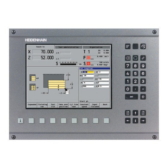
- Page 72 Assume the tool (cursor is on the position T 1): Press the Take over tool soft key Assume the cutting speed and feed rate: Press the S, F from tool soft key HEIDENHAIN MANUALplus 4110 Linear Machining Example...
- Page 73 The contour is described “completely” (including form elements) Call the ICP editor. Press the Edit ICP soft key Press the Insert element soft key Contour element 1 (chamfer) Press the Form elements menu key HEIDENHAIN MANUALplus 4110 Linear Machining Example...
- Page 74 Special feed rate F: No entry Conclude entry: Press the Save soft key “Unresolved elements” are shown as symbols below the graphics window Contour element 2 (thread undercut) Press the Form elements menu key HEIDENHAIN MANUALplus 4110 Linear Machining Example...
- Page 75 Target point X in X: 40 mm Target point Z in Z: –35 mm Angle A to the Z axis: No entry Length of line L: No entry Special feed rate F: No entry HEIDENHAIN MANUALplus 4110 Linear Machining Example...
- Page 76 Describe the contour element: Target point Z in Z: –55 mm Length of line L: No entry Special feed rate F: No entry Conclude entry: Press the Save soft key HEIDENHAIN MANUALplus 4110 Linear Machining Example 7.10...
- Page 77 Contour element 6 (vertical line) Press the Line menu key Describe the contour element: Target point X in X: 55 mm Length of line L: No entry Special feed rate F: No entry HEIDENHAIN MANUALplus 4110 Linear Machining Example 7.11...
- Page 78 Press the Form elements menu key Press the Chamfer menu Describe the contour element: Chamfer width B: 2 mm Special feed rate F: No entry Conclude entry: Press the Save soft key HEIDENHAIN MANUALplus 4110 Linear Machining Example 7.12...
- Page 79 Contour element 9 (vertical line) Press the Line menu key Describe the contour element: Target point X in X: 60 mm Length of line L: No entry Special feed rate F: No entry HEIDENHAIN MANUALplus 4110 Linear Machining Example 7.13...
- Page 80 Exit the input mode: Press the Back soft key Enter the contour name Press the Contour list soft Press the Change text soft Enter the contour name “Threaded stud” HEIDENHAIN MANUALplus 4110 Linear Machining Example 7.14...
- Page 81 Create the ICP contour “Threaded stud” Press the Take over text soft key Exit the contour list: Press the Back soft key Exit the ICP editor, return to cycle programming: Press the Back soft key HEIDENHAIN MANUALplus 4110 Linear Machining Example 7.15...
- Page 82 Press the Graphics soft key Warnings The MANUALplus 4110 tests whether the cycle can be performed without error. Because of the cutting geometry, “residual material” remains in this example. This leads to a warning (see the soft key Warning no.: 1).
- Page 83 Activate Cycle Start Slowly increase the feed rate override. The roughing cycle is performed. Run each block by pressing Cycle Start (single block mode) Save the cycle: Press the Save soft key HEIDENHAIN MANUALplus 4110 Linear Machining Example 7.17...
- Page 84 Enter the cycle parameters: Sequence Q: 0 (approach the tool change position on a diagonal path) Tool number T: 1 (maintain T1) Conclude entry: Press the Input finished soft key HEIDENHAIN MANUALplus 4110 Linear Machining Example 7.18...
- Page 85 Activate Cycle Start Slowly increase the feed rate override. The tool moves to the tool change position. Insert finishing tool T6 Save the cycle: Press the Save soft key HEIDENHAIN MANUALplus 4110 Linear Machining Example 7.19...
- Page 86 Press the Copy cycle soft Place the cursor in front of the insert position: Press the arrow key Press the Add cycle soft The new cycle and all parameters are inserted below the cursor position. HEIDENHAIN MANUALplus 4110 Linear Machining Example 7.20...
- Page 87 Position the cursor on T6: Press the arrow key repeatedly Assume the tool: Press the Take over tool soft key Assume the cutting speed and feed rate: Press the S, F from tool soft key HEIDENHAIN MANUALplus 4110 Linear Machining Example 7.21...
- Page 88 Press the Graphics soft key Call the additional functions of the simulation: Press the Extra functions soft key Press the Track soft key Press the Slide soft key HEIDENHAIN MANUALplus 4110 Linear Machining Example 7.22...
- Page 89 Activate Cycle Start again Slowly increase the feed rate override. The finishing cycle is performed. Measure the created diameter and correct the tool if necessary: Retract with the handwheel Measure the diameter HEIDENHAIN MANUALplus 4110 Linear Machining Example 7.23...
- Page 90 0.04 mm) Assume the compensation: Press the Save soft key The saved compensation value is shown in the T6 dx field (example: 0.04 mm) Conclude compensation: Press the Back soft key HEIDENHAIN MANUALplus 4110 Linear Machining Example 7.24...
- Page 91 The tool compensation and finishing cycle can be repeated as often as necessary until the correct dimension is reached. Program the “Approach tool change position” cycle Press the Add cycle soft Press the Single cuts menu HEIDENHAIN MANUALplus 4110 Linear Machining Example 7.25...
- Page 92 Activate Cycle Start Slowly increase the feed rate override. The tool moves to the tool change position. Use the threading tool T8 Save the cycle: Press the Save soft key HEIDENHAIN MANUALplus 4110 Linear Machining Example 7.26...
- Page 93 Thread depth U: No entry First cutting depth I: No entry Tool number T: 8 Shaft speed S: 600 m/min Assume the tool number and technology data from the tool file (see following steps). HEIDENHAIN MANUALplus 4110 Linear Machining Example 7.27...
- Page 94 Assume the tool: Press the Take over tool soft key Assume the shaft speed from the tool file: Press the S, F from tool soft key Press the Input finished soft key HEIDENHAIN MANUALplus 4110 Linear Machining Example 7.28...
- Page 95 Press the Contour view soft key Warnings If Contour view is selected, the MANUALplus 4110 checks all previous machining procedures. In this example the already known warning from the roughing cycle is output. Check and confirm warnings: ...
- Page 96 Check the thread and correct the tool, if necessary. The threading cycle is finished: Retract with the handwheel Measure the thread Thread paths are always machined at the programmed feed rate (thread pitch), regardless of the current feed-rate override. HEIDENHAIN MANUALplus 4110 Linear Machining Example 7.30...
- Page 97 0.04 mm) Assume the compensation: Press the Save soft key The saved compensation value is shown in the T8 dx field (example: 0.04 mm) Conclude compensation: Press the Back soft key HEIDENHAIN MANUALplus 4110 Linear Machining Example 7.31...
- Page 98 Press the Last cut soft key Activate Cycle Start Save the cycle: Press the Save soft key The tool compensation and the “last cut” can be repeated as often as necessary until the thread is correct. HEIDENHAIN MANUALplus 4110 Linear Machining Example 7.32...
- Page 99 Sequence Q: 0 (approach the tool change position on a diagonal path) Tool number T: 8 (maintain T8) Press the Input finished soft key Test the cycle: Press the Graphics soft key HEIDENHAIN MANUALplus 4110 Linear Machining Example 7.33...
- Page 100 Activate Cycle Start Slowly increase the feed rate override. The tool moves to the tool change position. Save the cycle: Press the Save soft key Exit “Teach-in”: Press the Back soft key HEIDENHAIN MANUALplus 4110 Linear Machining Example 7.34...
- Page 101 Create the “Threaded stud” cycle program Results: The workpiece The cycle program “Threaded stud” The ICP contour “Threaded stud” HEIDENHAIN MANUALplus 4110 Linear Machining Example 7.35...
- Page 102 HEIDENHAIN MANUALplus 4110 Linear Machining Example 7.36...
- Page 103 The roughing tool T1 and finishing tool T6 is defined and measured The workpiece datum is defined The tool change point is defined The protection is defined and activated The maximum shaft speed is defined HEIDENHAIN MANUALplus 4110 Surface Machining Example...
- Page 104 Right edge K: 1 mm Clamping range B: 20 mm Type of clamping J: 1 Press the Input finished soft key Test the cycle: Press the Graphics soft key HEIDENHAIN MANUALplus 4110 Surface Machining Example...
- Page 105 Tool number T: 1 Cutting speed S: 200 m/min Feed rate per revolution F: 0.4 mm/rev Assume the tool number and technology data from the tool file. Press the Input finished soft key HEIDENHAIN MANUALplus 4110 Surface Machining Example...
- Page 106 Set the feed rate override feed rate override to 0% Activate Cycle Start Slowly increase the feed rate override. The roughing cycle is performed. Save the cycle: Press the Save soft key HEIDENHAIN MANUALplus 4110 Surface Machining Example...
- Page 107 Set the feed rate override feed rate override to 0% Activate Cycle Start Slowly increase the feed rate override. The tool moves to the tool change position. When the tool change position is reached: Insert finishing tool T6 HEIDENHAIN MANUALplus 4110 Surface Machining Example...
- Page 108 Tool number T: 6 Cutting speed S: 220 m/min Feed rate per revolution F: 0.25 mm/rev Assume the tool number and technology data from the tool file. Press the Input finished soft key HEIDENHAIN MANUALplus 4110 Surface Machining Example...
- Page 109 Press the Track soft key Press the Slide soft key Conclude setting of the additional functions: Press the Back soft key Repeat the simulation with new settings: Press the Graphics soft key HEIDENHAIN MANUALplus 4110 Surface Machining Example...
- Page 110 Save the cycle: Press the Save soft key Program the “Approach tool change position” cycle Press the Add cycle soft Press the Single cuts menu Press the Rapid traverse positioning menu key HEIDENHAIN MANUALplus 4110 Surface Machining Example...
- Page 111 Set the feed rate override feed rate override to 0% Activate Cycle Start Slowly increase the feed rate override. The tool moves to the tool change position. Save the cycle: Press the Save soft key HEIDENHAIN MANUALplus 4110 Surface Machining Example...
- Page 112 Create the “Matrix” cycle program Results: The workpiece The “Matrix” cycle program The “Matrix” ICP contour for roughing machining The “Matrix” ICP contour for finishing machining HEIDENHAIN MANUALplus 4110 Surface Machining Example 8.10...
-
Page 113: Create The Matrix Icp Contour
Create an ICP contour: Call the ICP editor: Press the Edit ICP soft key Press the Contour list soft ICP Contour: 2 Enter the ICP contour number Press the Select soft key HEIDENHAIN MANUALplus 4110 Surface Machining Example 8.11... - Page 114 Contour element 2 (horizontal line) Press the Line menu key Describe the contour element: Target point Z in Z: –17 mm Length of line L: No entry Special feed rate F: No entry HEIDENHAIN MANUALplus 4110 Surface Machining Example 8.12...
- Page 115 Angle A to Z axis: 81.5° Length of line L: No entry Special feed rate F: No entry Conclude entry: Press the Save soft key (The oblique cut is an “unresolved element.”) HEIDENHAIN MANUALplus 4110 Surface Machining Example 8.13...
- Page 116 Special feed rate F: No entry Conclude entry: Press the Save soft key (There are two solutions.) Display next solution: Press the Next solution soft key (desired solution) Press the Select solution soft key HEIDENHAIN MANUALplus 4110 Surface Machining Example 8.14...
- Page 117 Special feed rate F: No entry Conclude entry: Press the Save soft key (There are two solutions.) Display next solution: Press the Next solution soft key (desired solution) Press the Select solution soft key HEIDENHAIN MANUALplus 4110 Surface Machining Example 8.15...
- Page 118 Press the Rounding menu Describe the superimposed element: Rounding radius B: 1 mm Special feed rate F: No entry Insert rounding: Press the Save soft key (Next position for superimposing is shown) HEIDENHAIN MANUALplus 4110 Surface Machining Example 8.16...
- Page 119 Press the Rounding menu Describe the superimposed element: Rounding radius B: 3.5 mm Special feed rate F: No entry Insert rounding: Press the Save soft key (Next position for superimposing is shown) HEIDENHAIN MANUALplus 4110 Surface Machining Example 8.17...
- Page 120 Describe the superimposed element: Rounding radius B: 1 mm Special feed rate F: No entry Insert rounding: Press the Save soft key All contour transitions are “imposed.” The “Matrix” ICP contour is complete. HEIDENHAIN MANUALplus 4110 Surface Machining Example 8.18...
- Page 121 Enter the contour name “Matrix” Press the Take over text soft key Exit the contour list: Press the Back soft key Exit the ICP editor: Press the Back soft key HEIDENHAIN MANUALplus 4110 Surface Machining Example 8.19...
- Page 122 “21” in the to field Perform copying: Press the Copy Yes soft key Change the contour name: Press the Change text soft Enter the contour name “Matrix – finishing contour” HEIDENHAIN MANUALplus 4110 Surface Machining Example 8.20...
- Page 123 Reverse the direction of the ICP contour description: Press the Turn contour soft key The small yellow rectangle indicates the end of the contour. Exit the ICP editor: Press the Back soft key HEIDENHAIN MANUALplus 4110 Surface Machining Example 8.21...
- Page 124 HEIDENHAIN MANUALplus 4110 Surface Machining Example 8.22...
-
Page 125: Create Form Roll Cycle Program
The workpiece blank is clamped The recessing tool T10 is defined, measured and inserted The workpiece datum is defined The tool change point is defined The protection is defined and activated The maximum shaft speed is defined HEIDENHAIN MANUALplus 4110 Recess Machining Example... -
Page 126: Program Cycle Blank—Bar/Tube
Right edge K: 1 mm Clamping range B: 20 mm Type of clamping J: 1 Press the Input finished soft key Test the cycle: Press the Graphics soft key HEIDENHAIN MANUALplus 4110 Recess Machining Example... - Page 127 Create the “Form roll” cycle program Conclude entry: Press the Save soft key Program the “ICP cut radial” cycle: Press the Add cycle soft Press the Recessing cycles menu key HEIDENHAIN MANUALplus 4110 Recess Machining Example...
-
Page 128: Run Graphic Simulation Of Cycle
Run a graphic simulation of the cycle The tool-path simulation accounts for the exact geometry of the tool tip. Therefore, this simulation is recommended for the recessing process. Press the Graphics soft key HEIDENHAIN MANUALplus 4110 Recess Machining Example... - Page 129 Stop the simulation after every traverse path: Press the Single block soft Test the cycle: Press the Graphics soft key Display subsequent traverse paths: Press the Graphic Continue soft key repeatedly HEIDENHAIN MANUALplus 4110 Recess Machining Example...
- Page 130 Set the feed rate override feed rate override to 0% Activate Cycle Start Slowly increase the feed rate override. The recessing cycle is performed. Save the cycle: Press the Save soft key HEIDENHAIN MANUALplus 4110 Recess Machining Example...
- Page 131 Tool number T: 10 Cutting speed S: 120 m/min Feed rate per revolution F: 0.2 mm/rev (The cycle parameters assumed from roughing are used for finishing.) Press the Input finished soft key HEIDENHAIN MANUALplus 4110 Recess Machining Example...
- Page 132 Set the feed rate override feed rate override to 0% Activate Cycle Start Slowly increase the feed rate override. The recess finishing cycle is performed. Save the cycle: Press the Overwrite soft HEIDENHAIN MANUALplus 4110 Recess Machining Example...
- Page 133 Set the feed rate override feed rate override to 0% Activate Cycle Start Slowly increase the feed rate override. The tool moves to the tool change position. Save the cycle: Press the Save soft key HEIDENHAIN MANUALplus 4110 Recess Machining Example...
- Page 134 Create the “Form roll” cycle program Results: The workpiece The “Form roll” cycle program The “Form roll” ICP contour HEIDENHAIN MANUALplus 4110 Recess Machining Example 9.10...
- Page 135 Target point Z in Z: –5 mm Length of line L: No entry Special feed rate F: No entry The line connects tangentially to the subsequent element: Press the Tangential transition soft key HEIDENHAIN MANUALplus 4110 Recess Machining Example 9.11...
- Page 136 Target point Z in Z: No entry Radius B: 5 mm Special feed rate F: No entry Conclude entry: Press the Save soft key (The arc is an “unresolved element.”) HEIDENHAIN MANUALplus 4110 Recess Machining Example 9.12...
- Page 137 Length of line L: No entry Special feed rate F: No entry Conclude entry: Press the Save soft key (There are two solutions.) Display next solution: Press the Next solution soft key (desired solution) HEIDENHAIN MANUALplus 4110 Recess Machining Example 9.13...
- Page 138 Target point Z in Z: –34 mm Angle A to Z axis: No entry Length of line L: No entry Special feed rate F: No entry Conclude entry: Press the Save soft key HEIDENHAIN MANUALplus 4110 Recess Machining Example 9.14...
- Page 139 Target point Z in Z: –49 mm Angle A to Z axis: No entry Length of line L: No entry Special feed rate F: No entry Conclude entry: Press the Save soft key HEIDENHAIN MANUALplus 4110 Recess Machining Example 9.15...
- Page 140 Length of line L: No entry Special feed rate F: No entry Conclude entry: Press the Save soft key Conclude the “rough contour” input: Press the Back soft key HEIDENHAIN MANUALplus 4110 Recess Machining Example 9.16...
- Page 141 Press the Rounding menu Describe the contour element: Rounding radius B: 1.5 mm Special feed rate F: No entry Insert rounding: Press the Save soft key (Next position for superimposing is shown) HEIDENHAIN MANUALplus 4110 Recess Machining Example 9.17...
- Page 142 Press the Rounding menu Describe the superimposed element: Rounding radius B: 1.5 mm Special feed rate F: No entry Insert rounding: Press the Save soft key (Next position for superimposing is shown) HEIDENHAIN MANUALplus 4110 Recess Machining Example 9.18...
- Page 143 Rounding radius R: 1.5 mm Special feed rate F: No entry Insert rounding: Press the Save soft key All contour transitions are “imposed.” The “Form roll” ICP contour is complete. HEIDENHAIN MANUALplus 4110 Recess Machining Example 9.19...
- Page 144 Enter the contour name “Form roll” Press the Take over text soft key Exit the contour list: Press the Back soft key Exit the ICP editor: Press the Back soft key HEIDENHAIN MANUALplus 4110 Recess Machining Example 9.20...
- Page 145 DIN program. The simulation supports the following views: Wire frame graphics The MANUALplus 4110 draws the traverse paths as lines. The theoretical tool tip is the reference point. This view is well suited for showing machining passes. Cutting path graphics In this view the cutter geometry of the tool is taken into consideration.
- Page 146 Press the Back soft key Repeat the simulation with new settings: Press the Graphics soft key Set the machining simulation: Press the Machining simulation soft key Start the simulation: Press the Graphic Continue soft key HEIDENHAIN MANUALplus 4110 Graphic Simulation 10.2...
- Page 147 Increase the section: Press the Page back key Move the section: Press the arrow keys Assume the selected section: Press the Take over soft Start the simulation: Press the Graphic Continue soft key HEIDENHAIN MANUALplus 4110 Graphic Simulation 10.3...
- Page 148 Enlarging, reducing, selecting a section for enlargement Extend the view “Extending the view” decreases the size of the workpiece. You then select the section desired. Press the Extend view soft HEIDENHAIN MANUALplus 4110 Graphic Simulation 10.4...
- Page 149 Run a graphic simulation of the cycle program Activate program run: Call the main menu: Press the Menu key Press the Program run soft (The program edited or used most recently is loaded.) HEIDENHAIN MANUALplus 4110 Executing Programs 11.1...
- Page 150 Press the arrow keys Press the Select soft key Warnings The MANUALplus 4110 checks the program when it loads it. The error symbol appears if there are errors or warnings. Display warning: Press the Info key ...
- Page 151 Press the arrow key Run a graphic simulation of the program Place the cursor at the beginning of the program: Press the Program start soft key Press the Graphics soft key HEIDENHAIN MANUALplus 4110 Executing Programs 11.3...
- Page 152 The protection is defined and activated The maximum shaft speed is defined The cycle program has been checked Run cycles individually If “Continuous run” is disabled, the MANUALplus 4110 stops after each cycle. Place the cursor at the beginning of the program:...
-
Page 153: Tool Compensation
The tool compensation is then entered and the finishing cycle is repeated. Interrupt the program run Initial situation: Several workpieces have already been produced. The finishing tool is worn. Deactivate the “Continuous run” mode: Press the Continuous run soft key HEIDENHAIN MANUALplus 4110 Executing Programs 11.5... - Page 154 (Tool correct. is already active) No compensation values have been entered yet. DX und DZ have the value 0. Enter the compensation value (0.2 mm) in the DX + field HEIDENHAIN MANUALplus 4110 Executing Programs 11.6...
- Page 155 Activate the “Continuous run” mode: Press the Continuous run soft key (Cycles are run continuously, without interruption, up to the next tool change.) Repeat the finishing cycle, then run the other cycles HEIDENHAIN MANUALplus 4110 Executing Programs 11.7...
- Page 156 HEIDENHAIN MANUALplus 4110 Executing Programs 11.8...
Need help?
Do you have a question about the MANUALPLUS 4110 and is the answer not in the manual?
Questions and answers