Yaesu VX-8DR - APRS Manual
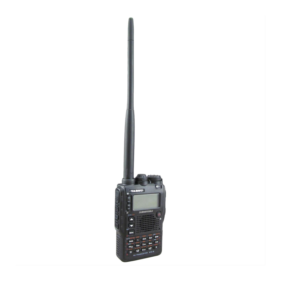
50/144/430 mhz triple-band heavy duty submersible transceiver
Hide thumbs
Also See for VX-8DR - APRS:
- Operating manual (177 pages) ,
- Operating manual (180 pages) ,
- Operating manual (180 pages)
Table of Contents
Advertisement
Quick Links
50/144/430 MHz
TRIPLE-BAND HEAVY DUTY
SUBMERSIBLE TRANSCEIVER
VX-8DR
O
M
PERATING
ANUAL
VERTEX STANDARD CO., LTD.
4-8-8 Nakameguro, Meguro-Ku, Tokyo 153-8644, Japan
VERTEX STANDARD
US Headquarters
10900 Walker Street, Cypress, CA 90630, U.S.A.
YAESU UK LTD.
Unit 12, Sun Valley Business Park, Winnall Close
Winchester, Hampshire, SO23 0LB, U.K.
VERTEX STANDARD HK LTD.
Unit 5, 20/F., Seaview Centre, 139-141 Hoi Bun Road,
Kwun Tong, Kowloon, Hong Kong
VERTEX STANDARD ( AUSTRALIA ) PTY., LTD.
Normanby Business Park, Unit 14/45 Normanby Road
Notting Hill 3168, Victoria, Australia
Advertisement
Table of Contents

Related Manuals for Yaesu VX-8DR - APRS


Summary of Contents for Yaesu VX-8DR - APRS
- Page 1 4-8-8 Nakameguro, Meguro-Ku, Tokyo 153-8644, Japan VERTEX STANDARD US Headquarters 10900 Walker Street, Cypress, CA 90630, U.S.A. YAESU UK LTD. Unit 12, Sun Valley Business Park, Winnall Close Winchester, Hampshire, SO23 0LB, U.K. VERTEX STANDARD HK LTD. Unit 5, 20/F., Seaview Centre, 139-141 Hoi Bun Road, Kwun Tong, Kowloon, Hong Kong VERTEX STANDARD ( AUSTRALIA ) PTY., LTD.
-
Page 2: Table Of Contents
Introduction ................. 1 Programmable (Band Limit) Memory Scan (PMS) ....68 Controls &Connections ............... 2 “Priority Channel” Scanning (Dual Watch) ......69 Display Icons & Indicators ............3 Priority Revert Mode ............70 Automatic Lamp Illumination on Scan Stop ......71 Keypad Functions ............... -
Page 3: Introduction
AM broadcast reception. Listen to FM broadcasts in stereo with your stereo headset/earphone! We appreciate your purchase of the VX-8DR, and encourage you to read this manual thor- oughly, and learn about the many exciting features of your thrilling new Yaesu hand-held transceiver! VX-8DR O... -
Page 4: Controls &Connections
& C ONTROLS ONNECTIONS LED Light This white LED will DIAL Knob glow (or flash) dur- MIC/SP Jack The main tuning ing “Emergency This 7-pin minia- Dial is used to set Channel” opera- ANTENNA Jack ture jack connects the operating fre- Connect the sup- tion. -
Page 5: Display Icons & Indicators
& I ISPLAY CONS NDICATORS “B” Band Display Icon REQUENCY ONTROL OLUME EVEL VFO: VFO Mode TX P OWER EVEL MR: Memory Mode HI: High Power (5 W) Memory Tune Mode L3: LOW3 Power (2.5 W) HOM: Home Channel Memory L2: LOW2 Power (1 W) PMS: Programmable Memory Scan Mode L1: LOW1 Power (0.02 W) -
Page 6: Keypad Functions
EYPAD UNCTIONS Increases the VFO Switches the “Upper” Switches the “Lower” frequency by one step or frequency to be the frequency to be the moves the memory channel “Operating” (TX) Band. “Operating” (TX) Band. to the next-highest channel. Tunes the VFO frequency No Action No Action upward in 1 MHz steps. - Page 7 EYPAD UNCTIONS Decreases the VFO USA Version: Disables the Noise Activate the APRS (Automatic frequency by one step or and Tone Squelch System. Position Reporting System) moves the memory channel EXP Version: Activates the T.CALL function. to the next-lowest channel. (1750 Hz) for repeater access.
-
Page 8: Accessories & Option
& O CCESSORIES PTIONS VX-8DR Antenna 1 pc YHA-65 (for USA version: Q3000185) or YHA-64 (for EXP version: Q3000183) FNB-101LI (7.4V/1,100mAh: AAG10X001) Li-Ion Battery Pack 1 pc Battery Charger 1 pc NC-86B (for USA version: Q9500149) or NC-86C (for EXP version: Q9500150) Connector Unit 1 pc (CB4392001) -
Page 9: Available Options For Your Vx-8R
Availability of accessories may vary. Some accessories are supplied as stan- dard per local requirements, while others may be unavailable in some re- gions. Consult your Yaesu Dealer for details regarding these and any newly- available options. Connection of any non-Yaesu approved accessory, should it cause damage, may void the Lim- ited Warranty on this apparatus. -
Page 10: Installation Of Accessories
NSTALLATION OF CCESSORIES The supplied antenna provides good results over the entire frequency range of the trans- ceiver. However, for enhanced base station medium-wave and shortwave reception, you may wish to connect an external (outside) antenna. The supplied antenna consists of two sections: the “Base Antenna”... -
Page 11: Installation Of Fnb-101Li Battery Pack
NSTALLATION OF CCESSORIES FNB-101LI B The FNB-101LI is a high-performance Lithium-Ion battery providing high capacity in a very compact package. Under normal use, the FNB-101LI may be used for approxi- mately 300 charge cycles, after which operating time may be expected to decrease. An old battery pack, which is displaying diminished capacity should be replaced with a new one. -
Page 12: Battery Life Information
NSTALLATION OF CCESSORIES When the battery charge is almost depleted, a “Low Voltage” indicator will appear on the display. When this icon appears, it is recommended that you charge the battery soon. FNB-101LI FNB-102LI FBA-39 50 MHz 5.5 hours 9.0 hours 20 hours : Full battery power 144 MHz... -
Page 13: Installation Of Fba-39 Alkaline Battery Case
NSTALLATION OF CCESSORIES FBA-39 A The optional FBA-39 Battery Case allows receive monitoring using three “AA” size Al- kaline batteries. Alkaline batteries can also be used for low power transmission in an emergency. The power output will only be selectable 1 W/50 mW (for 50/144/430 MHz FM) or 500 mW/50 mW (for 222 MHz FM), or 1 W fixed (for 50 MHz AM). -
Page 14: Interface Of Packet Tncs
ACKET The VX-8DR may be used for Packet operation, using the optional CT-M11 MIC/SP Connection Cable (available from your Yaesu dealer) for easy interconnection to com- monly-available connectors wired to your TNC. The audio level from the receiver to the TNC may be adjusted by rotating the DIAL knob while pressing and holding the key, as with voice operation. -
Page 15: Operation
PERATION Hi! I’m R. F. Radio, and I’ll be helping you along as you learn the many features of the VX-8DR. I know you’re anxious to get on the air, but I en- courage you to read the “Operation” section of this manual as thoroughly as possible, so you’ll get the most out of this fantastic new transceiver. -
Page 16: Squelch Adjustment
PERATION The VX-8DR’s Squelch system allows you to mute the background noise when no signal is being received. Not only does the Squelch system make “standby” operation more pleasant, it also significantly reduces battery current consumption. The Squelch system may be adjusted independently for the FM and Wide-FM (FM Broad- cast) modes. -
Page 17: Selecting The Operating Band
PERATION In the factory default configuration, the VX-8DR operates in the “Dual Receive” mode. During Dual Receive operation, the “A-Band” frequency will be displayed on the upper part of the LCD, and the “B-Band” frequency will be displayed on the lower part. The “Operating”... -
Page 18: Selecting The Frequency Band
PERATION The VX-8DR covers an incred- ibly wide frequency range, over “VFO-A” “VFO-B” [ 1 ] SW Band 1.8-30 MHz – which a number of different op- [ 2 ] 50 MHz Band 30-76 MHz 30-76 MHz erating modes are used. There- [ 3 ] AIR Band 108-137 MHz... -
Page 19: Frequency Navigation
PERATION The VX-8DR will initially be operating in the “VFO” mode, as just described. This is a fre- quency step system which allows free tuning throughout the currently-selected operating band. Three basic frequency navigation methods are available on the VX-8DR: Rotation of the DIAL knob allows tuning in the pre-pro- grammed steps established for the current operating band. -
Page 20: Scanning
PERATION From the VFO mode, press and hold in the key for one second, and while still holding in the key, rotate the DIAL knob to select the bandwidth for the VFO scan- ner. Release the key to begin scanning toward a higher frequency. -
Page 21: Transmission
PERATION Once you have set up an appropriate frequency inside one of the three (or four) Amateur bands on which the VX-8DR can transmit (50 MHz, 144 MHz, or 430 MHz, plus 222 MHz on the USA version), you’re ready to transmit. These are the most basic steps; more advanced aspects of transmitter operation will be discussed later. -
Page 22: Vox Operation
PERATION 1 ) The VX-8DR is smart! You can set up Low power on one band (like UHF), while leaving VHF on High power, and the radio will remember the different settings on each band. And when you store memories, you can store High and Low power settings separately in each memory, so you don’t waste battery power when using very close-in repeaters! 2 ) When you are operating on one of the Low power settings, you can press the... - Page 23 PERATION Adjust the VOX “Hang-Time” (the transmit-receive delay after the cessation of speech) from the Set Mode Item 109: VOX DELAY. The default delay is 0.5 second. To set a different delay time: 1. Press and hold in the key for one second to enter the Set mode. 2.
-
Page 24: Am And Fm Broadcast Reception
PERATION FM B The VX-8DR includes provision for reception of AM and FM broadcasts. FM broadcast reception, utilizes a wide-bandwidth filter and stereo decoder which provides excellent fidelity. The AM and FM Broadcast reception is only possible on “VFO-A”. 1. Press the key briefly to engage the “VFO-A”... - Page 25 PERATION FM B To select the antenna for the AM Broadcast Reception: 1. Press and hold the key for one second to enter the Set Mode. 2. Rotate the DIAL knob to select Set Mode Item 1: ANTENNA AM. 3. Press the key briefly to enable the antenna selection.
-
Page 26: Af-Dual Operation
PERATION FM B AF-D The AF-Dual Operation allows you to monitor two desired amateur band frequencies while also receiving an AM or FM broadcast station (Triple Watch functions!). When a signal is received in the amateur band, the amateur band audio is output instead of the AM or FM Broadcast station audio. - Page 27 PERATION FM B AF-D The VX-8DR allows you to select the resume mode of the AF-Dual Operation when a signal is received in the amateur band. 1. Press and hold the key for one second to enter the Set Mode. 2.
-
Page 28: Advanced Operation
DVANCED PERATION Now that you mastered the basics of VX-8DR operation, let’s learn more about some of the really neat features. In order to prevent accidental frequency change or inadvertent transmission, various keys and switches may be locked out. The possible lockout combinations are: Just the front panel keys are locked out KEY: Just the top panel DIAL is locked out... -
Page 29: Adjusting The Keypad Beeper Volume Level
DVANCED PERATION A keypad beeper provides useful audible feed back whenever a key button is pressed. The keypad beeper level changes according to the receiver audio volume level setting. How- ever, you may adjust the volume balance between the receiving audio and keypad beeper using Set Mode Item 11: BEEP LEVEL. -
Page 30: Audio Muting
DVANCED PERATION The Audio Mute feature is useful in situations where it would be helpful to reduce the audio level of the “Receive Only” band (Small character display) whenever you receive a signal on the “Main” band (Large character display) during Dual Receive operation. To activate the Audio Mute feature: 1. -
Page 31: Changing The Channel Steps
DVANCED PERATION The VX-8DR’s frequency synthesizer provides the option of utilizing tuning steps of 5, 6.25, 8.33, 9, 10, 12.5, 15, 20, 25, 50, 100, and 200 kHz per step. The VX-8DR is set up at the factory with different default steps for each operating band which are probably satisfac- tory for most operation. -
Page 32: Sql S-Meter
DVANCED PERATION SQL S- A special SQL (Squelch) S-meter feature is provided on this radio. This feature allows you to set the squelch so only signals exceeding a certain S-meter level will open the squelch. To set up the S-meter squelch feature for operation, use the following procedure: 1. -
Page 33: Repeater Operation
EPEATER PERATION Repeater stations, usually located on mountaintops or other high locations, provide a dra- matic extension of the communication range for low-powered hand-held or mobile trans- ceivers. The VX-8DR includes a number of features, which make repeater operation simple and enjoyable. -
Page 34: Manual Repeater Shift Activation
EPEATER PERATION If the ARS feature has been disabled, or if you need to set a repeater shift direction other than that established by the ARS, you may set the direction of the repeater shift manually. To do this: 1. Press the key, then press the key. -
Page 35: Checking The Repeater Uplink (Input) Frequency
EPEATER PERATION It often is helpful to be able to check the uplink (input) frequency of a repeater, to see if the calling station is within direct (“Simplex”) range. To do this, just press the key. You’ll notice that the display has shifted to the repeater uplink frequency. -
Page 36: Ctcss/Dcs/Epcs Operation
CTCSS/DCS/EPCS O PERATION CTCSS O Many repeater systems require that a very-low-frequency audio tone be superimposed on your FM carrier in order to activate the repeater. This helps prevent false activation of the repeater by radar or spurious signals from other transmitters. This tone system, called “CTCSS”... - Page 37 CTCSS/DCS/EPCS O PERATION CTCSS O 4. When you have made your selection of the CTCSS tone mode, press the key to save the new setting and exit to normal operation. 5. Press the key, then press the key. This provides a “Short-cut” to Set Mode Item 99: TONE FREQUENCY.
-
Page 38: Dcs Operation
CTCSS/DCS/EPCS O PERATION DCS O Another form of tone access control is Digital Code Squelch, or DCS. It is a newer, more advanced tone system which generally provides more immunity from false paging than does CTCSS. The DCS Encoder/Decoder is built into your VX-8DR, and operation is very similar to that just described for CTCSS. -
Page 39: Dcs Code Inversion
CTCSS/DCS/EPCS O PERATION DCS O DCS C The DCS system was first introduced in the commercial LMR (Land Mobile Radio) ser- vice, where it is now in widespread use. DCS is sometime referred to by its different ® ® proprietary names, such as DPL (Digital Private Line , a registered trademark of Motorola, Inc.). - Page 40 CTCSS/DCS/EPCS O PERATION DCS O RX-INVERT, TX-INVERT: Receive and transmit the Inverted DCS Tone. RX-BOTH, TX-INVERT: Receive both Normal and Inverted DCS Tones and transmit the Inverted DCS Tone. 5. When you have made your selection, press the PTT switch, to save the new settings and exit to normal operation.
-
Page 41: Tone Search Scanning
CTCSS/DCS/EPCS O PERATION In operating situations where you don’t know the CTCSS or DCS tone being used by another station, you can command the radio to listen to the incoming signal and scan in search of the tone being used. Two things must be remembered in this regard: You must be sure that your repeater uses the same tone type (CTCSS vs. -
Page 42: Epcs (Enhanced Paging & Code Squelch)
CTCSS/DCS/EPCS O PERATION EPCS E & C The VX-8DR includes an Enhanced CTCSS tone encoder/decoder and a dedicated micro- processor providing paging and selective calling features. This allows you to place a call to a specific station (Paging), and to receive calls of your choice directed only to you (Code Squelch). -
Page 43: Activating The Enhanced Paging & Code Squelch System
CTCSS/DCS/EPCS O PERATION EPCS E & C & C 1. Press the key, then press the key. This provides a “Short-cut” to Set Mode Item 95: SQL TYPE. 2. Rotate the DIAL knob until “PAGER” appears on the dis- play; this activates the Enhanced Paging & Code Squelch. 3. -
Page 44: Ctcss/Dcs/Epcs Bell Operation
CTCSS/DCS/EPCS O PERATION CTCSS/DCS/EPCS B During CTCSS Decode, DCS, or EPCS operation, you may set up the VX-8DR so that a ringing “bell” sound alerts you that a call is coming in. Here is the procedure for activating the CTCSS/DCS/EPCS Bell: 1. -
Page 45: Programming The User Melody
CTCSS/DCS/EPCS O PERATION CTCSS/DCS/EPCS B Three User Beep Memories are provided, allowing you to create unique original beep tone melodies. Each User Beep Memory can store up to 64 steps with three octaves (“C1” through “B3”). 1. Press and hold the key for one second to enter the Set Mode. -
Page 46: Split Tone Operation
CTCSS/DCS/EPCS O PERATION CTCSS/DCS/EPCS B 12. When you wish to add a beep tone into the beep melody strings, move the cursor to the place where you wish to en- ter the beep tone using the key, then press the key repeatedly until the “SELECT”... -
Page 47: Tone Calling (1750 Hz)
CTCSS/DCS/EPCS O PERATION 1750 H If the repeaters in your country require a 1750-Hz burst tone for access (typically in Eu- rope), you can set the key to serve as a “Tone Call” switch instead. To change the configuration of this switch, we again use the Menu to help us. 1. -
Page 48: Memory Mode (Regular Memory Channel Operation)
EMORY The VX-8DR provides a wide variety of memory system resources. These include: “Regular” Memory Channels, which include: 900 “Standard” memory channels, numbered “1” through “900.” 99 “Frequency Skip Memories,” numbered “901” through “999.” 11 “Home” channels, providing storage and quick recall of one prime frequency on each operating band. -
Page 49: Memory Storage
ODE R EMORY 1. Select the desired frequency, while operating in the VFO mode. Be sure to set up any desired CTCSS or DCS tones, as well as any desired repeater offset. The power level may also be set at this time, if you wish to store it. 2. -
Page 50: Memory Recall
ODE R EMORY “O ” All memories can store an independent transmit frequency, for operation on repeaters with non-standard shift. To do this: 1. Store the receive frequency using the method already described under M (it doesn’t matter if a repeater offset is active). 2. -
Page 51: Home Channel Memory
ODE R EMORY HOME C A special one-touch “HOME” channel is available for each operating band, to allow quick recall of a favorite operating frequency on each band. 1. Press the key, then press the key to recall the Home Channel on the band group where you are currently operat- ing. -
Page 52: Labeling Memories
ODE R EMORY You may wish to append an alpha-numeric “Tag” (label) to a memory or memories, to aid in recollection of the channel’s use (such as a club name, etc.). This is easily accomplished using the Set Mode. 1. Recall the memory channel on which you wish to append a label. -
Page 53: Memory Offset Tuning
ODE R EMORY Once you have recalled a particular memory channel, you may easily tune off that chan- nel, as though you were in the “VFO” mode. 1. With the VX-8DR in the Memory Recall (“MR”) mode, select the desired memory channel. -
Page 54: Masking Memories
ODE R EMORY There may be situations where you want to “Mask” memories so they are not visible during memory selection or scanning. For example, several memories used only in a city you visit infrequently may be stored, then “Masked” until you visit that city, at which time you can “Unmask”... -
Page 55: Memory Bank Operation
ODE R EMORY The large number of memories available in the VX-8DR could be difficult to utilize with- out some means of organizing them. Fortunately, the VX-8DR includes provision for dividing the memories into as many as 24 Memory Banks, so you can categorize the memories in a manner convenient to you. - Page 56 ODE R EMORY 5. To change to another Memory Bank, press the key, then press the key. Now rotate the DIAL knob to select the new Memory Bank, then press the key again. 6. To exit from Memory Bank operation, just press the key.
-
Page 57: Moving Memory Data To The Vfo
ODE R EMORY 10. If you make a mistake, press the key to backspace the cursor, then re-enter the correct letter, number, or symbol. 11. When you have completed the changes of the label, press the PTT switch to save the label and exit. -
Page 58: Memory Mode (Special Memory Channel Operation)
ODE S EMORY The VX-8DR provides Special Memory Channels, which are made up of: 10 Weather Broadcast Channels. 57 VHF Marine Channels 89 popular Short-wave Broadcast Station Memory Channels. 1) The Special Memory Channels are only recalled on the “A-Band” 2) You may assign the Special Memory Channels to a Memory Bank. -
Page 59: Vhf Marine Memory Channels
ODE S EMORY VHF M The VHF Marine Channel Bank has been pre-programmed at the factory, for quick selec- tion. 1. Press the key briefly to set the “A-Band” to the “Operating” band. 2. Press the key, then press the key, to recall the Spe- cial Memory Menu. -
Page 60: Short-Wave Broadcast Station Memory Channels
ODE S EMORY The Short-wave Broadcast Station Memory Channel Bank has been pre-programmed at the factory, for quick selection of Short-wave broadcast stations. 1. Press the key briefly to set the “A-Band” to the “Operating” band. 2. Press the key, then press the key, to recall the Spe- cial Memory Menu. - Page 61 VX-8DR O...
-
Page 62: Scanning
CANNING The VX-8DR allows you to scan just the memory channels, the entire operating band, or a portion of that band. It will halt on signals encountered, so you can talk to the station(s) on that frequency, if you like. Scanning operation is basically the same in each of the above modes. - Page 63 CANNING To set the Scan-Restart Delay Time: 1. Press and hold the key for one second to enter the Set Mode. 2. Rotate the DIAL knob to select Set Mode Item 82: SCAN RE-START. 3. Press the key briefly to enable adjustment of this Set Mode Item.
-
Page 64: Vfo Scanning
CANNING VFO S This mode allows you to scan on the VFO mode. 1. Select the VFO mode by pressing the key, if necessary. key, then rotate the DIAL knob while holding in the 2. Press and hold in the key (the current bandwidth for the VFO scanner will appear on the display) to select the bandwidth for the VFO scan- ner. -
Page 65: How To Skip (Omit) A Frequency During Vfo Scan
CANNING VFO S VFO S If the VFO scan stops on a frequency or frequencies that you do not need (such as a spurious radiation from a television), such frequencies can be “skipped” during VFO scan- ning. A special “Frequency Skip Memory” bank is reserved to store these frequencies. To skip a frequency during VFO scanning: 1. -
Page 66: Memory Scanning
CANNING Memory scanning is also easy to initiate: 1. Set the radio to the Memory Recall (“MR”) mode by pressing the key, if neces- sary. 2. Press and hold in the key, then rotate the DIAL knob while holding in the key (the current Memory Scan mode will appear on the fre- quency display) to select the desired Memory Scan mode. -
Page 67: How To Skip (Omit) A Channel During Memory Scan
CANNING As mentioned previously, some continuous-carrier stations like a Weather Broadcast sta- tion will seriously impede scanner operation if you are using the “Carrier Drop” Scan- Resume mode, as the incoming signal will not pause long enough for the transceiver to resume scanning. -
Page 68: Preferential Memory Scan
CANNING The VX-8DR also allows you to set up a “Preferential Scan List” of channels which you can “flag” within the memory system. These channels are designated by a blinking “ ” icon when you have selected them, one by one, for the Preferential Scan List. When you initiate memory scanning on a channel with the blinking “... -
Page 69: Memory Bank Scan
CANNING When the Memory Bank feature is engaged, the scanner sweeps only memory channels in the current Memory Bank. However, if the Memory Bank Link Scan feature is enabled, you may sweep the memory channels in several Memory Banks which you have selected. To enable the Memory Bank Link Scan feature: 1. -
Page 70: Programmable (Band Limit) Memory Scan (Pms)
CANNING This feature allows you to set sub-band limits for either scanning or manual VFO opera- tion. For example, you might wish to set up a limit (in North America) of 144.300 MHz to 148.000 MHz to prevent encroachment into the SSB/CW “Weak Signal” portion of the band below 144.300 MHz. -
Page 71: Priority Channel" Scanning (Dual Watch)
CANNING “P ” S The VX-8DR’s scanning features include a two-channel scanning capability which al- lows you to operate on a VFO or Memory channel, while periodically checking a user- defined Memory Channel for activity. If a station is received on the Memory Channel which is strong enough to open the Squelch, the scanner will pause on that station in accordance with the Scan-Resume mode set via Menu Item 83: SCAN RESUME. -
Page 72: Priority Revert Mode
CANNING “P ” S During Priority channel operation (Dual Watch), a special feature is available which will allow you to move to the Priority Channel instantly, without waiting for activity to appear on the Priority Channel. When this feature is enabled, and priority monitoring is engaged, just press the microphone’s PTT switch. -
Page 73: Automatic Lamp Illumination On Scan Stop
CANNING The VX-8DR will automatically illuminate the LCD Lamp whenever the scanner stops on a signal; this allows you to see the frequency of the incoming signal better at night. Note that this will, of course, increase battery consumption, so be sure to switch it off during the day (the default condition for this feature is “ON”). -
Page 74: Operation
® PERATION Installation of the optional BU-1 Adapter Unit will enable, the VX-8DR to send/receive voice messages with the optional BH-1A or BH-2A Headset via wireless links. When using the Headset for the first time, the Headset and the VX-8DR must be paired. 1. -
Page 75: Activation
® PERATION 1. Press and hold the key for one second to enter the Set Mode. 2. Rotate the DIAL knob to select Set Mode Item 17: BLUETOOTH SET. 3. Press the key briefly to enable selection of this Set Mode Item. - Page 76 ® PERATION Press the key, then rotate the DIAL knob to select the “POWR” parameter to “OFF”. 8. Press the PTT switch of the VX-8DR to save the new set- ting and return to normal operation. 1. When the BH-1A ( or BH-2A ) is correctly recognized by the VX-8DR, “ ”...
- Page 77 VX-8DR O...
-
Page 78: Gps Operation
GPS O PERATION The VX-8DR allows the display of your position (Longitude/Latitude) when using the optional FGPS-2 GPS Antenna Unit. 1. Make sure that the transceiver is off. 2. Connect the optional FGPS-2 GPS Antenna Unit to the MIC/SP jack of the trans- ceiver via the optional MH-74 Waterproof Speaker Microphone or CT-136 GPS Antenna Adapter (see next page). - Page 79 GPS O PERATION 3) You may memorize your current position as plotted by the GPS (up to ten points can be saved) via the APRS/GPS Set Mode Item 21: MY POSITION. See page 165 for details. FGPS-2 GPS Antenna Unit Installation Using the MH-74 Waterproof Speaker/Microphone 1.
-
Page 80: Setting The Time Zone (Time Offset)
GPS O PERATION You may customize the Time Zone (Time Offset), Display Unit of the GPS screen, and GPS Datum for your own operating requirements via the APRS/GPS Set Mode. Sets the time offset between your local time and UTC (Universal Time Coordinated or GMT: Greenwich Mean Time) shown on the display. -
Page 81: Selecting The Display Units Of The Gps Screen
GPS O PERATION GPS S 1. Press the key until the GPS screen appears. 2. Press and hold the key for one second to enter the APRS/ GPS Set Mode. 3. Rotate the DIAL knob to select Set Mode Item 18: GPS UNIT. -
Page 82: Aprs ® Operation
® APRS PERATION The VX-8DR is equipped with a 1200/9600bps AX.25 Data Modem to enable APRS ® (Automatic Packet Reporting System) operation. The Automatic Packet Reporting Sys- tem (APRS ® ) is a software program and registered trademark of Bob Bruninga, WB4APR. Before performing any APRS ®... - Page 83 ® APRS PERATION key, then rotate the DIAL knob to preset icons. To choose another icon, press the select the desired symbol after having selected the preset icon. When you have com- pleted selecting the icon, press the key again. You may choose 1 of 46 different symbols.
- Page 84 ® APRS PERATION knob to select the desired numbers in each col- umn. Repeat for each column to complete your latitude entry. 4) Move the cursor to “Lat” using the and then rotate the DIAL knob one click clockwise to select “Lon”.
-
Page 85: Receiving An Aprs Beacon
® APRS PERATION APRS B 1. Set the “B-Band” to the APRS frequency. 144.390 MHz is generally used in North America. If you don’t know the APRS frequency of your country, ask your dealer. The AX.25 modem cannot be activated in the “A-Band”. 2. - Page 86 ® APRS PERATION APRS B Deleting a Received Beacon from the “STATION LIST” 1. Press the key several times until the STATION LIST screen appears on the display. 2. Rotate the DIAL knob (or press the keys) to select the beacon station to be deleted. 3.
-
Page 87: Transmit An Aprs Beacon
APRS ® PERATION APRS B RANSMIT AN EACON To transmit your APRS Beacon, just press the key. The VX-8DR allows you to transmit your APRS Beacon automatically and repeatedly via the APRS/GPS Set Mode. 1. Press the key several times until the STATION LIST screen appears on the display. - Page 88 APRS ® PERATION APRS B RANSMIT AN EACON You may store five Status Text Messages (up to the 60 characters for each memory), and you may transmit one of these Status Text Messages with the APRS Beacon. 1. Press the key several times until the STATION LIST screen appears on the display.
- Page 89 ® APRS PERATION APRS B The VX-8DR allows you to set up to eight digipeaters for the APRS Packet Path. The VX-8DR is preset to “WIDE1-1” and “WIDE1-1, WIDE2-1” digi-path to insure that your transmitted APRS Beacon is repeated by the new-N paradigm digipeaters. We rec- ommend that you use this setting by default.
-
Page 90: Receiving An Aprs Message
® APRS PERATION APRS M 1. Set the “B-Band” to the APRS frequency. 144.390 MHz is generally used in North America. If you don’t know the APRS frequency for your country, ask your dealer. The AX.25 modem is not activated in the “A-Band”. 2. - Page 91 5. Press the key to select the “Group” you wish to utilize (G1 ALL, G2 CQ, G3 QST, or G4 YAESU). 6. If you add a new message group code and/or bulletin group code, select “G5” (for message group code) or “B1” ~ “B3”...
-
Page 92: Transmit An Aprs Message
® APRS PERATION APRS M 1. Press the key several times until the APRS MESSAGE screen appears on the display. 2. Press the key to enter the “EDIT” mode. 3. Any previously stored message may be cleared using the following procedures. 1) Press the 2) Press the key to select the “ALL CLEAR”. - Page 93 ® APRS PERATION APRS M the display, instead of the remain- ing number of transmissions. You may select the num- bers and letters for the callsign and message with the key buttons ( through , and ) in the same way as labeling memories. The VX-8DR allows you to store five fixed form messages (up to 16 characters for each message).
-
Page 94: Arts (Automatic Range Transponder System)
ARTS The ARTS feature uses DCS signaling to inform both parties when you and another ARTS -equipped station are within communications range. This may be particularly useful during Search-and Rescue situations, where it is important to stay in contact with other members of your group. -
Page 95: Basic Arts Setup And Operation
ARTS ARTS 1. Set your radio and the other radio(s) to the same DCS code number, per the discussion on page 36. 2. Press the key, then press the key. You will observe the “OUT RANGE” display on the LCD below the operating frequency. - Page 96 ARTS ARTS The ARTS feature allows two kinds of alert beeps (with the additional option of turning them off), to alert you to the current status of ARTS operation. Depending on your location and the potential annoyance associated with frequent beeps, you may choose the Beep mode which best suits your needs.
-
Page 97: Cw Identifier Setup
ARTS CW I The ARTS feature includes a CW identifier, as discussed previously. Every ten minutes operation, the radio can be instructed to send “DE (your callsign) K” if during ARTS this feature is enabled. The callsign field may contain up to 16 characters. Here is how to program the CW Identifier: 1. -
Page 98: Spectrum Analyzer Operation
PECTRUM NALYZER PERATION The Spectrum Analyzer allows viewing operating activity on channels above or below the current operating channel in the VFO mode. The display indicates the relative signal strength on channels immediately adjacent to the current operating frequency. The Spectrum Analyzer feature can be activated only on the “A-Band” while the VX- 8DR is in the “Mono”... - Page 99 VX-8DR O...
-
Page 100: Channel Counter Operation
HANNEL OUNTER PERATION The Channel Counter allows measuring of the frequency of a nearby transmitter, without knowing that frequency in advance. The frequency can be measured by bringing the VX- 8DR close to the transceiver which is transmitting. The VX-8DR performs a high-speed search within a ±5 MHz range from the frequency displayed on the LCD. - Page 101 HANNEL OUNTER PERATION You may change the bandwidth of the Channel Counter. Available selections are ±5, ±10, ±50, and ±100 MHz (default: ±5 MHz). Here is the procedure for setting the Channel Counter Bandwidth: 1. Press and hold the key for one second to enter the Set Mode. 2.
-
Page 102: Smart Search Operation
MART EARCH PERATION The Smart Search feature allows you to load frequencies automatically according to where activity is encountered by your radio. When Smart Search is engaged, the transceiver will search above and below your current frequency, storing active frequencies as it goes (with- out stopping on them even briefly);... - Page 103 MART EARCH PERATION 6. To recall the Smart Search memories, rotate the DIAL to choose from among the Smart Search memories. 7. To return to normal operation, press the key. Smart Search is a great tool when visiting a city for the first time. You don’t need to spend hours looking up repeater frequencies from a reference guidebook…just ask your VX-8DR where the action is! VX-8DR O...
-
Page 104: Message Feature
ID. Note The Message Feature requires that all members (1) use the Yaesu VX-8DR, VX-8R, VX-3R, or FTM-10R/SR transceiver, (2) store the same messages into the message slots, (3) store the same member list into the member box, and (4) set the same frequency. -
Page 105: Programming A Member List
ESSAGE EATURE 9. Repeat steps 7 and 8 above to complete the message (up to 16 characters). If you make a mistake, press the key to move back to the incorrect character, then re-enter the cor- rect character. 10. Press and hold in the key for one second to delete all data after the cursor that may have been previously stored. -
Page 106: Set Your Personal Id
ESSAGE EATURE character of the message you wish to store. Example 1: Rotate the DIAL knob to select any of the 61 available characters. Example 2: Press the key repeatedly to toggle among the nine available characters associated with that key: p p .. -
Page 107: Sending A Message
ESSAGE EATURE The registered message can be sent to the members who are receiving on the coordination frequency. When a message is sent, the transmitter’s ID will be sent also, and the receiver can identify who sent the message. The “Personal ID” setting (described in the previous paragraph) is required for the transmitter’s ID to be shown with the received message. -
Page 108: Receiving A Message
ESSAGE EATURE 1. Set the radio to the coordination frequency. 2. Press the key, then press the key. This provides a “Short-cut” to Set Mode Item 95: SQL TYPE. 3. Rotate the DIAL knob until “MESSAGE” appears on the display; this activates the Message feature. 4. -
Page 109: Emergency Feature
MERGENCY EATURE The VX-8DR includes an “Emergency” feature, which may be useful if you have some- one monitoring on the same frequency as your transceiver’s UHF “Home” channel. See page 49 for details on setting the Home channel. The “Emergency” feature is activated by pressing and holding in the key for one second. -
Page 110: Emergency Automatic Id (Eai) Feature
MERGENCY EATURE ID EAI F The Emergency Automatic ID (EAI) feature can be used to aid in searching for persons who are incapacitated in disasters like earthquakes, especially search-and-rescue person- nel who may have become injured in a debris field. When using the EAI feature, a searcher transmits a unique command (CTCSS tone pair), which will automatically cause the in- jured party’s radio to transmit, so others may perform direction-finding and effect a res- cue. -
Page 111: Selecting The Eai Mode And Its Transmit Time
MERGENCY EATURE ID EAI F 1. Press and hold the key for one second to enter the Set Mode. 2. Rotate the DIAL knob to select Set Mode Item 33: EAI TIME. 3. Press the key briefly to enable adjustment of this Set Mode Item. -
Page 112: Using The Eai Feature
MERGENCY EATURE ID EAI F 1. Recall the Memory Channel “EAI” (must be the same as the searched person’s radio), which is found in the next to the last “regular” memory channel. 2. Set the CTCSS tone pair to the same CTCSS tone pair stored in the Receiving Pager Code Memory of the missing person’s radio. -
Page 113: Internet Connection Feature
NTERNET ONNECTION EATURE The VX-8DR can be used to access a “node” (repeater or base station) which is tied into the Vertex Standard WIRES™ (Wide-Coverage Internet Repeater Enhancement System) network, operating in the “SRG” (Sister Radio Group) mode. Details may be found at the WIRES-II Web site: http://www.vxstd.com/en/wiresinfo-en/. -
Page 114: Frg ("Friendly Radio Group") Mode
NTERNET ONNECTION EATURE FRG “F ” M ™ You may access other Internet Link Systems (including WIRES in the FRG mode) that use a DTMF string for access. Load the DTMF tones which you wish to use for Internet-link access into an Internet Memory Register. - Page 115 NTERNET ONNECTION EATURE FRG “F ” M 16. When you have stored an access code that is less than 8 digits, press the twice to confirm the code and enable storing the access code; otherwise, just enter the 8 digits and press the key one time.
-
Page 116: Dtmf Operation
DTMF O PERATION The VX-8DR’s keypad allows easy DTMF dialing for Autopatch, repeater control, or Internet-link access purposes. Besides numerical digits [ 0 ] through [ 9 ] , the keypad in- cludes the [ ] and [ ] digits, plus the [ A ] , [ B ] , [ C ] , and [ D ] tones often used for repeater control. - Page 117 DTMF O PERATION You may check your work by monitoring the entered DTMF string. To do this, repeat steps 1 - 4 above, then press the key. To send a telephone number: 1. Press the key, then press the key. This provides a “Short-cut”...
-
Page 118: Cw Learning Feature
CW L EARNING EATURE The VX-8DR provides a CW learning feature, which sends the designated Morse Code via the sidetone (heard in the speaker) to help your CW learning. 1. Press and hold the key for one second to enter the Set Mode. 2. - Page 119 CW L EARNING EATURE The “CPM” selection is based on the international “PARIS” standard, which stipulates five characters per word. VX-8DR O...
-
Page 120: Cw Training Feature
CW T RAINING EATURE The VX-8DR provides another CW learning feature; call it a CW Training feature, which sends random Morse Code via the sidetone (heard in the speaker), so you can improve your CW proficiency. 1. Press and hold the key for one second to enter the Set Mode. -
Page 121: Sensor Mode
ENSOR The VX-8DR always displays the “Battery Voltage” and “Current Time” while the VX- 8DR is operating in the “Mono” band mode with the Large characters, the VX-8DR can display various information provided by internal sensors. Avail- able selections are “Battery Voltage”, “Temperature”, “Audio Wave-form”, “Current Barometric Pressure”, “Current Altitude”, and “off”. -
Page 122: Sensor Mode Options
ENSOR The VX-8DR has a 24-hour clock with a calendar which covers all dates from January 1, 2000 through December 31, 2099 (accuracy: ±30 sec/month). To set the clock: 1. Press and hold the key for one second to enter the Set Mode. 2. -
Page 123: Selecting The Measurement Units Of The Sensor Unit
ENSOR 1. Press and hold the key for one second to enter the Set Mode. 2. Rotate the DIAL knob to select Set Mode Item 104: UNIT SELECT. 3. Press the key briefly to enable adjustment of this Set Mode Item. 4. -
Page 124: Miscellaneous Setting
ISCELLANEOUS ETTING The VX-8DR provides a password feature which can minimize the chance that your trans- ceiver could be used by an unauthorized party. When the password feature is activated, the radio will ask for the four digit password to be entered when the radio is first turned on. -
Page 125: Programming The [ Internet ( Txpo )] Key
ISCELLANEOUS ETTING The Internet Key is the factory default (“primary” press key) function of the key. However, you may change the “primary” (press key) function of the key to another function via the Menu mode. 1. Press and hold the key for one second to enter the Set Mode. -
Page 126: Att (Front End Attenuator)
ISCELLANEOUS ETTING ATT F The attenuator will reduce all signals (and noise) by 10 dB, and it may be used to make reception more pleasant under extremely noisy conditions. 1. Set a band (“A-Band” or “B-Band”) on which you wish to activate the “attenuator” to the “Operating”... -
Page 127: Receive Battery Saver Setup
ISCELLANEOUS ETTING An important feature of the VX-8DR is its Receive Battery Saver, which “puts the radio to sleep” for a time interval, periodically “waking it up” to check for activity. If somebody is talking on the channel, the VX-8DR will remain in the “active” mode, then resume its “sleep”... -
Page 128: Disabling The Busy Indicator
ISCELLANEOUS ETTING BUSY I Further battery conservation may be accomplished by disabling the BUSY indicator (the green LED inside the key) while receiving a signal. Use the following procedure: 1. Press and hold the key for one second to enter the Set Mode. 2. -
Page 129: Transmitter Time-Out Timer (Tot)
ISCELLANEOUS ETTING The TOT feature provides a safety switch which limits transmission to a pre-programmed value. This will promote battery conservation by not allowing you to make excessively long transmissions, and in the event of a stuck PTT switch (perhaps if the radio or a Speaker/Mic is wedged between car seats) it can prevent interference to other users as well as battery depletion. -
Page 130: On/Off Preset Timer
ISCELLANEOUS ETTING ON/OFF P The VX-8DR includes the capability to turn itself on/off at preset time. If you use these features, you must first set the VX-8DR’s clock, as described previously (page 120). ON T 1. Press and hold the key for one second to enter the Set Mode. -
Page 131: Busy Channel Lock-Out (Bclo)
ISCELLANEOUS ETTING BCLO The BCLO feature prevents the radio’s transmitter from being activated if a signal strong enough to break through the “noise” squelch is present. On a frequency where stations using different CTCSS or DCS codes may be active, BCLO prevents you from disrupting their communications accidentally (because your radio may be muted by its own Tone Decoder). -
Page 132: Changing The Microphone Gain
ISCELLANEOUS ETTING At the factory, a microphone gain has been programmed that should be satisfactory for the internal microphone. If you use the radio under the noisy environment, you may wish to set a different microphone gain level. 1. Press and hold the key for one second to enter the Set Mode. -
Page 133: Display Contrast
ISCELLANEOUS ETTING The LCD’s contrast may be adjusted for best viewing in sunlight or darkness allowing for best readability using the Set Mode Item. 1. Press and hold the key for one second to enter the Set Mode. 2. Rotate the DIAL knob to select Set Mode Item 48: LCD CONTRAST. -
Page 134: My Bands Operation
ISCELLANEOUS ETTING The “My Bands” feature allows you to select several operating bands, and make only those bands available for selection via the key. For example, if you do not need the reception of the SW and Air bands, you may skip (omit) these bands from the band selection loop. -
Page 135: Changing The Status Of The [ Vol ] Key
ISCELLANEOUS ETTING By factory default, the key keeps the status while pressing and holding the down. You may change the status of the key to keep the status for approximately three seconds after pressing the key, after which time it reverts back to its previous status. -
Page 136: Reset Procedures
ESET ROCEDURES In some instances of erratic or unpredictable operation, the cause may be corruption of data in the microprocessor (due to static electricity, etc.). If this happens, resetting of the microprocessor may restore normal operation. Note that all memories will be erased if you do a complete microprocessor reset, as described below. -
Page 137: Cloning
LONING The VX-8DR includes a convenient “Clone” feature, which allows the memory and con- figuration data from one transceiver to be transferred to another VX-8DR. This can be particularly useful when configuring a number of transceivers for a public service opera- tion. -
Page 138: Set Mode
The VX-8DR Set Mode, already described in parts of many previous chapters, is easy to activate and set. It may be used for configuration of a wide variety of transceiver param- eters, some of which have not been detailed previously. Use the following procedure to activate the Set Mode: 1. - Page 139 The VX-8DR has nine types of cursor symbol formats for the Set Mode operation. You may change the default setting to any of the available symbols. 1. Press and hold the key for one second to enter the Set Mode. 2.
- Page 140 1: ANTENNA AM Select the antenna to be used in the AM Broadcast listening. BAR & EXT / BAR ANTENNA 2: ANTENNA FM Select the antenna to be used in the FM Broadcast listening. EXT ANTENNA / EAR PHONE 3: ANTENNA ATT Enables/Disables the receiver Front-end Attenuator.
- Page 141 55: MEMORY SKIP Selects the Memory Scan channel-selection mode. OFF / SKIP / ONLY 56: MEMORY WRITE Determines the method of selecting channels for Memory Storage. NEXT / LOWER 57: MESSAGE LIST Programming a Member List for the Message feature. 58: MESSAGE REGISTER Selects your Personal ID for the Message feature.
- Page 142 Enables/Disables the Automatic Repeater Shift function. RPT ARS ON / OFF Sets the Repeater Shift Direction. RPT SHIFT SIMPLEX / -RPT / +RPT Sets the magnitude of the Repeater Shift. RPT SHIFT FREQ 0.000MHz ~ 150.000MHz (50 kHz/step) CTCSS/DCS/EPCS S Selects the number of Bell ringer repetitions.
- Page 143 DTMF S Selects the DTMF Autodialer Delay Time. DTMF DELAY 50ms / 250ms / 450ms / 750ms / 1000ms Enables/Disables the DTMF Autodial feature. DTMF MANUAL/AUTO MANUAL / AUTO Programming the DTMF Autodialer. DTMF SELECT Selects the DTMF Autodialer Sending Speed. DTMF SPEED 50mS / 100mS Set the duration that a secondary function of the [ F/W ] key (press and holding the [ F/W ] key) is held...
- Page 144 1: ANTENNA AM Function: Select the antenna to be used for the AM Broadcast listening. Available Values: BAR & EXT / BAR ANTENNA Default: BAR & EXT BAR & EXT: Use both the internal Bar Antenna and the Rubber Flex Antenna. BAR ANTENNA: Use the internal Bar Antenna only.
- Page 145 6: ARTS INTERVAL Function: Select the Polling Interval during ARTS operation. Available Values: 15sec / 25sec Default: 25sec This setting determines how often the other station will be polled during ARTS operation. 7: BANK LINK Function: Enables/Disables the Memory Bank Link Scan. See page 67 for details. 8: BANK NAME Function: Stores Alpha-Numeric “Tag”...
- Page 146 14: BELL RINGER Function: Selects the number of Bell ringer repetitions. Available Values: 1Time ~ 20Times / CONTINUOUS Default: 1Time 15: BELL SELECT Function: Enables/Disables the Bell ringer function and its sound selection. Available Values: OFF / BELL / USER BP1 / USER BP2 / USER BP3 Default: OFF 16: BLUETOOTH P-CODE Function: Pairing the...
- Page 147 Disable the Battery Save function of the BH-1A/BH-2A SAVE: OFF: Headset. POWR: ON: Enable the BU-1 Unit. Disable the BU-1 POWR: OFF: Unit. 18: BUSY LED Function: Enables/Disables the BUSY LED while the squelch is open. Available Values: ON / OFF Default: ON 19: CH COUNTER Function: Selects the Channel Counter Search Width.
- Page 148 26: DCS CODE Function: Setting of the DCS code. DCS CODE Available Values: 104 standard DCS codes. Default: DCS 023 27: DCS INVERSION Function: Enables/Disables the “Inverted” DCS tone. Available Values: RX-NORMAL, TX-NOR- MAL / RX-INVERT, TX-NORMAL / RX-BOTH, TX-NORMAL / RX-NORMAL, TX-INVERT / RX-INVERT, TX-INVERT / RX-BOTH, TX-INVERT Default: RX-NORMAL, TX-NORMAL...
- Page 149 32: EAI Function: Enables/Disables the Emergency Automatic ID (EAI) feature. Available Values: ON / OFF Default: OFF 33: EAI TIME Function: Sets the Emergency Automatic ID (EAI) operating mode and its transmit time. Available Values: INT 1min ~ INT 9min / INT10min / INT15min / INT20min / INT30min / INT40min / INT50min / CON 1min ~ CON 9min / CON10min / CON15min / CON20min / CON30min / CON40min / CON50min Default: CON 5min...
- Page 150 3. Rotate the DIAL knob, or press one of the keyboard keys, to select the first letter/ number of the message. Example 1: Rotate the DIAL knob to select any of the 39 available characters. Example 2: Press the key repeatedly to toggle among the seven available charac- ters associated with that key: A 4.
- Page 151 39: HOME/REVERSE Function: Selects the function of the key. Available Values: HOME / REV Default: REV HOME: Pressing the key instantly recalls a favorite “Home” channel. REV: Pressing the key reverses transmit and receive frequencies during repeater operation. 40: INT MANUAL/AUTO Function: Enables/Disables the DTMF Autodialer feature while using the Internet Con- nection feature (WIRES ).
- Page 152 44: INTERNET MODE Function: Selects the operating mode of the Internet Connection feature (WIRES ). Available Values: FRG / SRG Default: SRG 45: INTERNET SELECT Function: Programming of the Access Number (DTMF code) for the FRG station of the WIRES (or non WIRES Internet Link System) access.
- Page 153 51: LOCK Function: Selects the combination of key buttons that are locked out by the LOCK func- tion. Available Values: KEY / DIAL / KEY&DIAL / PTT / KEY&PTT / DIAL&PTT / ALL Default: KEY&DIAL 52: MEMORY FAST STEP Function: Selects the channel step for the fast channel selection mode while in the Memory Recall mode.
- Page 154 58: MESSAGE REGISTER Function: Selects your Personal ID for the Message feature. See page 104 for details. 59: MESSAGE SELECT Function: Programming a Message for the Message feature. See page 102 for details. 60: MIC GAIN Function: Adjusts the microphone gain level. Available Values: LEVEL 1 ~ LEVEL 9 Default: LEVEL 5 61: MONI/T-CALL...
- Page 155 65: OPENING MESSAGE Function: Selects the Opening Message that appears when the radio is powered on. Available Values: NORMAL / OFF / DC / MESSAGE Default: NORMAL NORMAL: Appears the Vertex Standard Logo. OFF: No Opening Message. Appears the Vertex Standard Logo with the current time and the power supply voltage.
- Page 156 69: PASSWORD Function: Programming and activating the Password feature. See page 122 for details. 70: PR FREQUENCY Function: Program the CTCSS Tone Frequency for the User Programmed Reverse CTCSS Decoder. Available Values: 300 Hz ~ 3000 Hz (100 Hz/step) Default: 1600 Hz 71: PRI REVERT Function: Enables/Disables the Priority Revert feature.
- Page 157 77: RX AF DUAL Function: Select the resume mode of the AF-Dual Operation. Available Values: TRX 1sec ~ TRX 10sec / HOLD / TX 1sec ~ TX 10sec Default: TRX 2sec 78: RX MODE Function: Sets the receiving mode. Available Values: AUTO / NFM / AM / WFM Default: AUTO (Mode automatically changes according to operating frequency).
- Page 158 83: SCAN RESUME Function: Selects the Scan Resume mode. Available Values: 2.0sec ~ 10.0sec (0.5sec/step) /BUSY / HOLD Default: 5.0sec 2.0sec - 10.0sec: The scanner will halt on a signal it encounters, and will hold there for the selected resume time. If you do not take action to disable the scanner within that time period, the scanner will resume even if the station is still active.
- Page 159 88: SMART SEARCH Function: Selects the Smart Search Sweep mode. Available Values: SINGLE / CONTINUOUS Default: SINGLE SINGLE: The transceiver sweeps the current band once in each direction starting on the current frequency. All channels where activity is present (up to 15 in each direction) are loaded into the Smart Search memories.
- Page 160 92: SQL LEVEL Function: Sets the Squelch threshold level. Available Values: LEVEL 0 ~ LEVEL 15 (AM and Narrow FM), LEVEL 0 ~ LEVEL 15 (Wide FM and AM Broadcast) Default: LEVEL 1 (AM and Narrow FM), LEVEL 2 (Wide FM and AM Broadcast) 93: SQL S-METER Function: Adjusts the Squelch threshold level to the S-meter level.
- Page 161 95: SQL TYPE Function: Selects the Tone Encoder and/or Decoder mode. Available Values: OFF / TONE / TONE SQL / DCS / REV TONE / PR FREQ / PAGER / MESSAGE Default: OFF TONE: Activates the CTCSS Encoder TONE SQL: Activates the CTCSS Encoder/Decoder DCS: Activates the Digital Coded Squelch Encoder/Decoder REV TONE: Activates the Reverse CTCSS Encoder/Decoder (Mutes the receiver when...
- Page 162 99: TONE FREQUENCY Function: Setting of the CTCSS Tone Frequency Available Values: 50 standard CTCSS tones Default: 100.0 Hz 100: TONE-SRCH MUTE Function: Enables/Disables the receiver audio output while the Tone Search Scanner is activated. Available Values: ON / OFF Default: ON 101: TONE-SRCH SPEED Function: Selects the Tone Search Scanner speed.
- Page 163 106: VFO SKIP Function: Set the My Band. Available Values: ON/OFF Default: OFF The “My Band” feature allows you to select several operating bands, and make only those bands available for selection via the key. ON: Only the bands that are turned on will be shown when pushing the key.
-
Page 164: Aprs/Gps Set Mode
19: MSG GROUP Selects the filter type option allowing you to receive only specified types of APRS Message G1 ~ G5, B1 ~ B3 information. (G1: ALL, G2: CQ, G3: QST, G4: YAESU) 20: MY CALLSIGN Program your callsign. 21: MY POSITION Determine and memorize your location (Lat/Log). - Page 165 APRS/GPS S APRS/GPS S APRS/GPS Set Mode Item 1: APRS AF DUAL Function: Enables/Disables the AF DUAL function when the APRS signal is received. Available Values: ON/OFF Default: OFF APRS/GPS Set Mode Item 2: APRS DESTINATION Function: Indicates the model code of this transceiver. Default: APY008 This model code can not be changed.
- Page 166 APRS/GPS S APRS/GPS S APRS/GPS Set Mode Item 9: APRS RINGER BCON Function: Enables/Disables the alert ringer when the APRS beacon is received. Available Values: ON/OFF Default: ON APRS/GPS Set Mode Item 10: APRS UNIT Function: Selects the unit for the APRS Beacon information. Available Values: Position: MM.MM’/MM’SS”, Distance: km/mile, Speed: km/h/knot/mph, Altitude: m/ft, Temp: °C/°F, Rain: mm/inch, Wind: m/s/mph Default: Position: MM.MM’, Distance: mile, Speed: mph, Altitude: ft, Temp: °F,...
- Page 167 Function: Selects the filter type option allowing you to receive only the specified types of APRS Message information. Available Values: G1 ~ G5, B1 ~ B3 Default: G1: ALL, G2: CQ, G3: QST, G4: YAESU, G5: non, B1 ~ B3: non VX-8DR O...
- Page 168 Function: Select your icon which will be displayed on the monitors of other stations as you. Available Values: more than 46 symbols Default: YY: Yaesu Radios APRS/GPS Set Mode Item 23: POSITION COMMENT Function: Selects position comment depending on your situation.
- Page 169 APRS/GPS S APRS/GPS S APRS/GPS Set Mode Item 24: SmartBeaconing Function: Selects the various parameter of the SmartBeaconing . The VX-8DR trans- mits the APRS beacon automatically when each parameter value exceed the set point. Available Values: OFF, TYPE1, TYPE2, or TYPE3 LOW SPEED: 2 ~ 30 mph HIGH SPEED: 3 ~ 70 mph SLOW RATE: 1 min ~ 100 min...
-
Page 170: Specifications
PECIFICATIONS A (Main) Band RX: 0.5-1.8 MHz (AM Radio) Frequency Ranges: 1.8-30 MHz (SW Band) 30-76 MHz (50 MHz HAM) 76-108 MHz (FM Radio) 108-137 MHz (Air Band) 137-174 MHz (144 MHz HAM) 174-222 MHz (VHF-TV) 222-420 MHz (General 1) 420-470 MHz (430 MHz HAM) 470-774 MHz (UHF-TV) 774-999.90 MHz (General 2, Cellular Blocked) - Page 171 PECIFICATIONS 50/144/430 MHz 1.0 W (@4.5 V: AA x 3) RF Power Output: 5.0 W (@7.4 V or EXT DC) 50 MHz AM 1.0 W (Fixed) 222 MHz (USA only) 0.5 W (@4.5 V: AA x 3) 1.5 W (@7.4 V or EXT DC) L3: 2.5 W, L2: 1 W, L1: 0.05 W (@7.4 V, 50/144/430 MHz) L3: 1 W, L2: 0.5 W, L1: 0.05 W (@7.4 V, 222 MHz) F2E, F3E: Variable Reactance...
-
Page 172: Installation Of The Bu-1 (Option)
BU-1 O NSTALLATION OF THE PTION 1. Make sure that the transceiver is off. Remove the hard or soft case, if used. 2. Remove the battery pack. 3. Locate the connector for the BU-1 under the Caution Seal in the battery compartment on the back of the transceiver, just peel off the Caution Seal (Figure 1). - Page 173 VX-8DR O...
- Page 174 VX-8DR O...
- Page 175 1. Changes or modifications to this device not expressly approved by VERTEX STANDARD could void the user’s authorization to operate this device. 2. This device complies with part 15 of the FCC Rules. Operation is subject to the following two conditions; (1) this device may not cause harmful interference, and (2) this device must accept any interference including interference that may cause undesired operation.
- Page 176 Copyright 2009 Printed in Japan VERTEX STANDARD CO., LTD. All rights reserved. No portion of this manual may be reproduced without the permission of VERTEX STANDARD CO., LTD. 0912-0M...
Need help?
Do you have a question about the VX-8DR - APRS and is the answer not in the manual?
Questions and answers