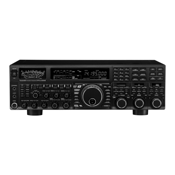
Yaesu FTDX5000 Operating Manual
Hf/50 mhz transceiver
Hide thumbs
Also See for FTDX5000:
- Reference (20 pages) ,
- Operating manual (148 pages) ,
- Software update (10 pages)
Table of Contents
Advertisement
Quick Links
See also:
Reference
HF/50 MH
T
Z
RANSCEIVER
FT
5000
DX
S
ERIES
O
M
PERATING
ANUAL
VERTEX STANDARD CO., LTD.
4-8-8 Nakameguro, Meguro-Ku, Tokyo 153-8644, Japan
VERTEX STANDARD
US Headquarters
10900 Walker Street, Cypress, CA 90630, U.S.A.
YAESU UK LTD.
Unit 12, Sun Valley Business Park, Winnall Close
Winchester, Hampshire, SO23 0LB, U.K.
VERTEX STANDARD HK LTD.
Unit 5, 20/F., Seaview Centre, 139-141 Hoi Bun Road,
Kwun Tong, Kowloon, Hong Kong
VERTEX STANDARD ( AUSTRALIA ) PTY., LTD.
Normanby Business Park, Unit 14/45 Normanby Road
Notting Hill 3168, Victoria, Australia
Advertisement
Table of Contents

Related Manuals for Yaesu FTDX5000


Summary of Contents for Yaesu FTDX5000
- Page 1 4-8-8 Nakameguro, Meguro-Ku, Tokyo 153-8644, Japan VERTEX STANDARD US Headquarters 10900 Walker Street, Cypress, CA 90630, U.S.A. YAESU UK LTD. Unit 12, Sun Valley Business Park, Winnall Close Winchester, Hampshire, SO23 0LB, U.K. VERTEX STANDARD HK LTD. Unit 5, 20/F., Seaview Centre, 139-141 Hoi Bun Road, Kwun Tong, Kowloon, Hong Kong VERTEX STANDARD ( AUSTRALIA ) PTY., LTD.
- Page 2 . . . BOUT ANUAL The FT 5000 is a leading-edge transceiver with a number of new and exciting features, some of which may be unfamiliar to you. In order to gain the most enjoyment and operating efficiency from your FT 5000, we recommend that you read this manual in its entirety, and keep it handy for reference as you explore the many capabilities of your new transceiver.
-
Page 3: General Description
Four TX/ RX antenna ports, plus a receive-only antenna port, are provided on the rear panel. The front and rear key jacks Whether this is your first rig, or Yaesu equipment is already may be configured independently, for paddle input, connec- the backbone of your station, rest assured this transceiver tion to a straight key, or computer-driven keying interface. -
Page 4: Table Of Contents
ABLE OF ONTENTS General Description ............. 1 Advanced Interference-Suppression Features: Accessories & Options ..........4 RF Front End ............. 54 Supplied Accessories ..........4 Using the VRF (Variable RF Front-end Filter) ..54 Available Options ............. 4 Interference Rejection Before You Begin ............6 (Signals Off Frequency by Just a Few kHz) .... - Page 5 ABLE OF ONTENTS CW Mode Operation ..........86 VFO and Memory Scanning ........107 Setup for Straight Key VFO Scanning ............107 (and Straight Key emulation) Operation ....86 Memory Scan ............108 Using the Built-in Electronic Keyer ....... 88 PMS ................
-
Page 6: Accessories & Options
& O CCESSORIES PTIONS UPPLIED CCESSORIES Hand Microphone ( MH-31 1 pc A07890001 Remote Control Keypad ( FH-2 ) 1 pc A07890001 AC Power Cord 1 pc T9017882: USA T9013285: Europe T9013283A: Australia 4-pin DIN Plug 1 pc P0091004 5-pin DIN Plug 1 pc P0091006 1/4-inch 3-contact Plug... - Page 7 5000 O Page 5 PERATING ANUAL...
-
Page 8: Before You Begin
EFORE EGIN AC P ONNECTING OWER The FT 5000 is equipped with a universal power sup- ply supporting 100 V to 264 V AC. Therefore, the FT 5000 will operate on a voltage range from 100V to 264 V without changing a voltage select switch. -
Page 9: Resetting The Microprocessor
EFORE EGIN ESETTING THE ICROPROCESSOR ESETTING EMORIES Use this procedure to reset (clear out) the previously stored Memory channels, without affecting any configuration changes you may have made to the Menu settings. 1. Press the front panel [ POWER ] switch to turn the trans- ceiver off. -
Page 10: Installation And Interconnections
NSTALLATION AND NTERCONNECTIONS NTENNA ONSIDERATIONS The FT 5000 is designed for use with any antenna system providing a 50 Ohm resistive impedance at the desired operat- ing frequency. While minor excursions from the 50-Ohm specification are of no consequence, if the Standing Wave Ratio (SWR) present at the Antenna jack is greater than 3:1, the Antenna Tuner may not be able to reduce the impedance mis- match to an acceptable value. -
Page 11: Grounding
NSTALLATION AND NTERCONNECTIONS ROUNDING The FT 5000 transceiver, like any other HF communications apparatus, requires an effective ground system for maxi- mum electrical safety and best communications effectiveness. A good ground system can contribute to station efficiency in a number of ways: It can minimize the possibility of electrical shock to the operator. -
Page 12: Connection Of Antenna And Power Cables
NSTALLATION AND NTERCONNECTIONS ONNECTION OF NTENNA AND OWER ABLES Follow the below illustration and advice regarding the proper connection of antenna coaxial cables, ground cable, and the AC power cable. Use a short, thick, braided cable to connect your station equipment to the buried ground rod (or alter- native earth ground system). -
Page 13: Connection Of Microphone And Headphone
NSTALLATION AND NTERCONNECTIONS ONNECTION OF ICROPHONE AND EADPHONE 5000 O Page 11 PERATING ANUAL... -
Page 14: Key, Keyer, And Computer-Driven Keying
NSTALLATION AND NTERCONNECTIONS EYER OMPUTER RIVEN EYING NTERCONNECTIONS The FT 5000 includes a host of features for the CW operator. These functions will be detailed in the “Operation” section later. An Electronic Keyer is built-in, and two key jacks are provided, one on the front and one on the rear panel, for convenient connection to keying devices. -
Page 15: Vl-1000 Linear Amplifier Interconnections
NSTALLATION AND NTERCONNECTIONS VL-1000 L INEAR MPLIFIER NTERCONNECTIONS Be sure both the FT 5000 and VL-1000 are turned off, then follow the installation recommendations contained in the illustration. Refer to the VL-1000 Operating Manual for details regarding amplifier operation. Do not attempt to connect or disconnect coaxial cables when your hands are wet. About the CONTROL Cable The VL-1000 may be operated with the 5000 whether or not the CONTROL Cable... -
Page 16: Interfacing To Other Linear Amplifiers
NSTALLATION AND NTERCONNECTIONS NTERFACING TO THER INEAR MPLIFIERS ANTENNA Cable RF OUT RF IN FUSE RELAY The TX/RX switching in the linear amplifier is con- trolled by switching components in the transceiver. The relay circuit of the FT 5000 used for this switching is capable of switching AC voltage of 100 Volts at up to 300 mA, or DC voltages of 60 V at 200 mA or 30 V at up to 1 Amp. -
Page 17: Plug/Connector Pinout Diagrams
ONNECTOR INOUT IAGRAMS ROTATOR SERIAL OUT CW ROTATION SERIAL IN DOWN CCW ROTATION FAST SPEED DIRECTION MIC GND (as viewed from front panel) (as viewed from rear panel) (as viewed from rear panel) BAND DATA PACKET RTTY +13V TX GND DATA IN SHIFT BAND DATA A... -
Page 18: Front Panel Controls & Switches
You cannot use a 2-contact plug in this jack (to do so produces a constant “key down” condition). Microphone Connector This 8-pin jack accepts input from a microphone uti- lizing a traditional YAESU HF-transceiver pinout. Page 16 5000 O PERATING... - Page 19 & S RONT ANEL ONTROLS WITCHES [ DIM ] Switch [ MONI ] ( Monitor ) Switch Press this button to lower the illumination intensity of This button enables the transmit monitor in all modes. the analog meter and the frequency display. Press it While activated, the “...
- Page 20 & S RONT ANEL ONTROLS WITCHES [ ATT ] Switch [ R.FLT ] Switch Move this knob up or down to select the degree of Move this knob up or down to select the bandwidth of Attenuation to be applied to the receiver input. the first IF Roofing Filter.
- Page 21 & S RONT ANEL ONTROLS WITCHES ( VFO-B ) [ NB ] [ AGC ] Switch [ SQL ] Knobs [ NB ] Knob Move this knob up and down to select the receiver AGC The inner [ NB ] knob adjusts the noise blanking characteristics (receiver-recovery time).
- Page 22 & S RONT ANEL ONTROLS WITCHES [ MIC ] [ RF PWR ] Knobs [ RF PWR ] Knob The outer [ RF PWR ] knob is the main RF Power [ MIC ] Knob output control for the transceiver. It is active in all The inner [ MIC ] knob adjusts the microphone in- operating modes.
- Page 23 & S RONT ANEL ONTROLS WITCHES [ SPEED ] [ PITCH ] Knobs [ VOX ] [ DELAY ] Knobs [ SPEED ] Knob [ VOX ] Knob The inner [ SPEED ] knob adjusts the keying speed The inner [ VOX ] knob sets the level of microphone of the internal CW keyer (4 ~ 60 WPM).
- Page 24 & S RONT ANEL ONTROLS WITCHES QMB ( Quick Memory Bank ) Switches [ A ] , [ B ] Switches [ STO ] ( Store ) Button Pressing the [ A ] or [ B ] button will illuminate the re- spective switch, and allow adjustment of the major Pressing this button, copies the operating informa- functions (such as mode and band selection etc) on the...
- Page 25 & S RONT ANEL ONTROLS WITCHES [ SPLIT ] Switch Main Tuning Dial Knob Press this button briefly to activate split frequency op- This large knob adjusts the operating frequency of eration between the VFO-A receiver and the VFO-B, VFO-A or a recalled memory. Clockwise rotation of transmit.
- Page 26 & S RONT ANEL ONTROLS WITCHES [ A B ] Switch [ A M ] Switch Press this button briefly to transfer data from the VFO- Pressing and holding in this button for 1/2 second (un- A frequency (or a recalled memory channel) to VFO- til the double beep), copies the current operating data B, overwriting any previous contents in VFO-B.
- Page 27 & S RONT ANEL ONTROLS WITCHES [ NB ] Switch [ RX CLAR ( FAST )] Switch The function of this button differs with the setting of This button turns the IF Noise Blanker on and off. the [ A/B ] button (described later) . Press this button briefly to reduce a short-duration pulse When the LED in the [ A/B ] button is turned off, press- noise;...
- Page 28 & S RONT ANEL ONTROLS WITCHES [ CLAR/GRP ] Switch ( VFO-B )[ RX ] Indicator/Switch This button has two functions. This is the button that turns the VFO-B receiver “On” Press this button briefly, the [ CLAR/VFO-B ] knob and “Off”.
- Page 29 & S RONT ANEL ONTROLS WITCHES ( VFO-A )[ VRF/μ-T ] Switch ( VFO-A )[ SHIFT ] Switch This button turns the VFO-A receiver VRF filter “on” Pressing this button allows you to move the IF DSP and “off”, and allows you to adjust the center frequency bandwidth of VFO-A “higher”...
- Page 30 & S RONT ANEL ONTROLS WITCHES ( VFO-A )[ NOTCH ] Switch ( VFO-A )[ DNF ] Switch This button turns the VFO-A receiver IF notch filter This button toggles the VFO-A Receiver Digital Notch “on” and “off”, and allows you to adjust the center fre- Filter “on”...
- Page 31 & S RONT ANEL ONTROLS WITCHES ( VFO-B )[ CONT/APF ] Switch ( VFO-B )[ CLEAR ] Switch In the SSB, AM, and FM modes, this button turns the Pressing this button will reset the function selected by VFO-B Receiver Contour Filter “on” and “off”, and the five buttons above and left of the button to factory enables adjustment of the Contour Filter center fre- default.
-
Page 32: Display Indications
NDICATIONS ( L ISPLAY ( VFO-A ) Block Diagram Display ( VFO-A ) Status Indicator ANT ( 1, 2, 3, 4, RX ) : Indicates the antenna selected for operation by the front This indicator appears during transmission on the VFO- panel [ ANT 1-4 ] and [ RX ANT ] switches. - Page 33 NDICATIONS ( L ISPLAY ( VFO-B ) Receiver S-Meter ( VFO-B ) Status Indicator Displays the strength of signals received on VFO-B. This indicator appears during transmission on the VFO- ( VFO-B ) Block Diagram Display B frequency. ANT ( 1, 2, 3, 4, RX ) : Indicates the antenna selected for operation by the front This indicator appears whenever the VFO-B receiver panel [ ANT 1-4 ] and [ RX ANT ] switches.
- Page 34 NDICATIONS ( R ISPLAY IGHT This indicator appears when the transmit monitor cir- This indicator appears while the voice recorder is play- cuit is activated. ing back the recorded audio, and/or the memory is play- ing back the recorded CW or voice message. This indicator appears when the internal CW keyer is activated.
-
Page 35: Rear Panel
This 6-pin MINI-DIN Jack accepts a cable connected ANT 1, 2, 3, 4 Jacks to a YAESU G-800DXA/-1000DXA/-2800DXA An- Connect your main antenna(s) here, using a type-M tenna Rotator (listed models are current as of early (PL-259) plug and coaxial feedline for each. These an- 2010). - Page 36 ANEL ONNECTIONS AF OUT Jack PTTJack This 3.5-mm, 3-contact jack provides dual-channel This RCA input jack may be used to provide manual low-level receiver output, for recording or external am- transmitter activation using a footswitch or other switching device. Its function is identical to the [ MOX ] plification.
- Page 37 The update software and instructions are configured for keyer, “Bug,” “straight key,” or com- available for download from the Vertex Standard puter keying interface operation via Menu item “059 website (http://www.yaesu.com/). A1A R-TYPE.” REMOTE Jack Main Power Switch By plugging the supplied FH-2 Remote Control Key- This is the main power “on”...
-
Page 38: Switches
FH-2 S WITCHES The supplied Remote Control Keypad “FH-2” can be used to control the voice memory capability for the SSB/AM/FM modes, and the contest memory keyer for the CW mode. You can also play-back up to 15 seconds of incoming received audio, for verification of a missed callsign or other purposes. -
Page 39: Basic Operation: Receiving On Amateur Bands
ASIC PERATION ECEIVING ON MATEUR ANDS Before turning on main power, please verify the following precautions once more. Verify all ground connections are secure. See page 9 for details. Connect the antenna(s) to the rear-panel Antenna jack(s). See page 10 for details. Connect the microphone (and/or key or paddle). - Page 40 ASIC PERATION ECEIVING ON MATEUR ANDS Here is the typical start-up procedure for normal operation: ( VFO-A )[ RX ] Button ( VFO-B )[ SQL ] Knob [( ) DOWN ] / [( ) UP ] Buttons [ POWER ] Switch [ ANTENNA ] Buttons ( VFO-A )[ SQL ] Knob [ FAST ] Button...
- Page 41 ASIC PERATION ECEIVING ON MATEUR ANDS I f y o u p r e s s t h e When operating on the FM mode [ BAND/MCH ] but- in the VFO-A, rotate the ( VFO- A )[ SQL ] (Squelch) knob clock- ton briefly, the button glows red, and the wise just to the point where the...
-
Page 42: Clar (Clarifier) Operation On Main (Vfo-A)
ASIC PERATION ECEIVING ON MATEUR ANDS CLAR ( C VFO-A LARIFIER PERATION ON The [ RX CLAR/FAST ] , [ CLEAR ] , [ TX CLAR/LOCK ] buttons, and the [ CLAR ( VFO-B )] knob are used to offset the receive, the transmit, or both frequencies from their settings on VFO-A (the Clarifier does not affect VFO-B). -
Page 43: Lock
ASIC PERATION ECEIVING ON MATEUR ANDS LOCK You may lock the setting of the Main Tuning Dial knob, to prevent accidental frequency change. To lock out the Main Tuning Dial knob, just press the [ LOCK ] Button [ LOCK ] button that is located to the right of the Main Tuning Dial knob. -
Page 44: Convenience Features
ONVENIENCE EATURES ECEIVE The FT 5000 is capable of simultaneous reception on the same amateur band, using the VFO-A and VFO-B receivers, in the “Dual Receive” mode. This is especially useful for DX work, here is the operating procedure for Dual Receive operation. -
Page 45: Using Headphones For Dual Receive
ONVENIENCE EATURES ECEIVE Using Headphones for Dual Receive Sideband Diversity Reception To take advantage of dual reception, you will want to con- Here you receive a single AM signal through the two re- nect stereo headphones to the PHONES jack. In addition ceivers, each receiving the opposite sideband. -
Page 46: Bandwidth Diversity Reception
ONVENIENCE EATURES ECEIVE Bandwidth Diversity Reception Polarity Diversity This mode involves receiving the same signal through two different bandpass filters. The frequency and mode of both Similar in concept to the bandwidth diversity just VFO-A and VFO-B are the same. VFO-A can be set up for described, another interesting capability of the a wide bandpass, using the [ WIDTH ] knobs, and VFO-B 5000 dual reception, is the ability to use two... -
Page 47: P.back (Audio Playback) From Main (Vfo-A) Receiver
ONVENIENCE EATURES P.BACK ( A ( VFO-A ) R UDIO LAYBACK FROM ECEIVER When Audio Playback is engaged by the operator, the FT 5000 begins automatically recording the last 15 seconds of incoming receiver audio on VFO-A. Recording is controlled with the supplied FH-2 Remote Control Keypad, plugged into the rear panel REMOTE jack. -
Page 48: My Bands" Operation
ONVENIENCE EATURES “MY B ” O ANDS PERATION When operating on an amateur band, it is possible to use the [ CLAR ( VFO-B )] knob to change the selected operating band. The “My Bands” feature allows you to designate several amateur bands, and make only those bands available for selection with the [ CLAR ( VFO-B )] knob. -
Page 49: Band Stack Operation
ONVENIENCE EATURES TACK PERATION The FT 5000 utilizes a triple band-stack VFO selection technique that permits you to store up to three favorite frequen- cies and modes onto each band’s VFO register. For example, you may store one frequency each on 14 MHz CW, RTTY, and USB, then recall each VFO by successive, momentary presses of the [ 14 ] MHz band button. -
Page 50: Rotator Control Functions
OTATOR ONTROL UNCTIONS When using a YAESU model G-800DXA, G-1000DXA, or G-2800DXA rotator (not supplied), it is possible to control it from the front panel of the FT 5000. [ 3.5 ( 2 )] , [ 7 ( 3 )] Button... -
Page 51: More Frequency Navigation Techniques
ONVENIENCE EATURES REQUENCY AVIGATION ECHNIQUES Using the [ ( DOWN )] / [ ( UP )] Buttons Keyboard Frequency Entry You may enter operating frequencies, for either the VFO- To tune the VFO-A frequency in 1 MHz step. Press the [ ( UP )] or [ ( DOWN )] but- A or VFO-B bands, using the front panel band/frequency selection keys. -
Page 52: Receiver Operation (Front End Block Diagram)
Therefore, the following information is provided as a general guideline for typical situations, and a starting point for your own experimentation. Yaesu provides the optional RF-μTUNING Unit (Narrow-bandwidth High-Q RF Filter) for additional protection from strong signal interference. IF NOTCH... -
Page 53: Ipo (Intercept Point Optimization)
ONVENIENCE EATURES IPO ( I NTERCEPT OINT PTIMIZATION The IPO feature allows the operator to optimize the characteristics of the receiver front end, depending on the current noise level and the strength of incoming signals. VFO-A IPO Setup VFO-B IPO Setup Press the [ A ] button to activate VFO-A receiver (The Press the [ B ] button to activate VFO-B receiver (The [ A ] button will glow red). -
Page 54: Att
ONVENIENCE EATURES Even with the IPO function on, extremely strong local signals or high noise can still degrade reception. In such situations, you can use the [ ATT ] button to insert 6, 12, or 18-dB of RF attenuation in front of the RF amplifier. VFO-A ATT Setup VFO-B ATT Setup Press the [ A ] button to activate VFO-A receiver (The... -
Page 55: Rf Gain (Ssb/Cw/Am Modes)
ONVENIENCE EATURES RF G AIN ( SSB/CW/AM M ODES The RF Gain controls permit manual adjustment of the receiver RF and IF stages gain levels, to account for noise and/or signal strength conditions. VFO-A Receiver RF GAIN Adjustment VFO-B Receiver RF GAIN Adjustment The ( VFO-A )[ RF GAIN ] knob should, be rotated, initially, The VFO-B receiver RF Gain operates identically to the to the clockwise position. -
Page 56: Rf Front End
DVANCED NTERFERENCE UPPRESSION EATURES RF F RONT The FT 5000 includes an unmatched array of RF selectivity-enhancing features. Please study the following material carefully, to understand the many interference tools and techniques completely. VRF ( V RF F SING THE ARIABLE RONT ILTER... - Page 57 DVANCED NTERFERENCE UPPRESSION EATURES RF F RONT VRF ( V RF F SING THE ARIABLE RONT ILTER : : : : : DVICE UICK OINT The VRF system tuning is relatively broad, although it The VRF filter utilizes high-quality coils and capacitors is still much narrower than the fixed bandpass filter.
-
Page 58: Interference Rejection (Signals Off Frequency By Just A Few Khz)
EJECTION ( S NTERFERENCE IGNALS REQUENCY BY UST A EW KHZ R.FLT ( R OOFING ILTERS Narrow-band Roofing Filters of 15 kHz, 6 kHz, 3 kHz, 600 Hz , and 300 Hz bandwidths are provided in the first IF, right after the first mixer. - Page 59 EJECTION ( S NTERFERENCE IGNALS REQUENCY BY UST A EW KHZ 5000 O Page 57 PERATING ANUAL...
-
Page 60: Interference Rejection (Signals Within 3 Khz)
EJECTION ( S NTERFERENCE IGNALS WITHIN CONTOUR C ONTROL PERATION The Contour Filter system produces a gentle perturbation of the IF filter passband. The different frequency components of the signal can be suppressed or enhanced, thus improving the sound and/or readability of the received signal. VFO-A Contour Operation VFO-B Contour Operation Press the ( VFO-A )[ CONT/APF ] button. - Page 61 EJECTION ( S NTERFERENCE IGNALS WITHIN CONTOUR C ONTROL PERATION Refer to Figure “B”, and notice the initial position of the contour when the [ CONT ] button is pushed. Ob- serve the “indentation” in the receiver passband where the contour filter is placing a low-Q “notch” (accord- ing to the setting of Menu item “112 RDSP CNTR LV”, as described on the previous page).
-
Page 62: If Shift Operation
EJECTION ( S NTERFERENCE IGNALS WITHIN IF SHIFT O PERATION ( SSB/CW/RTTY/PKT/AM M ODES The IF Shift allows you to vary the DSP filter passband higher or lower, (without changing the pitch of the incoming signal) to reduce or eliminate interference. Because the carrier tuning frequency is not varied, there is no need to re-tune the operating frequency when using the IF Shift to eliminating the interference. -
Page 63: Width (If Dsp Bandwidth) Tuning
EJECTION ( S NTERFERENCE IGNALS WITHIN WIDTH ( IF DSP B UNING ( SSB/CW/RTTY/PKT M ANDWIDTH ODES The IF Width tuning system allows you to vary the width of the DSP IF filter passband, to eliminate interference. Moreover, the bandwidth may actually be expanded from its default setting, should you wish to enhance incoming signal fidelity when interference on the band is low. -
Page 64: Using If Shift And Width Together
EJECTION ( S NTERFERENCE IGNALS WITHIN IF S OGETHER ( SSB/CW/RTTY/PKT/AM M SING HIFT AND IDTH ODES The IF Shift and Variable IF Width features, together, form a very effective interference-fighting filter system. For example, in Figure “A” you can see how interference has appeared both on the high and low sides of the desired Desired Signal Desired Signal... -
Page 65: If Notch Filter Operation
EJECTION ( S NTERFERENCE IGNALS WITHIN IF N PERATION ( SSB/CW/RTTY/PKT/AM M OTCH ILTER ODES The IF Notch filter is a highly effective system that allows you to slice out an interfering beat note or other carrier signal from inside the receiver passband. VFO-A IF Notch Operation VFO-B IF Notch Operation Press the ( VFO-A )[ NOTCH ] button. -
Page 66: Digital Noise Reduction (Dnr) Operation
EJECTION ( S NTERFERENCE IGNALS WITHIN ( DNR ) O IGITAL OISE EDUCTION PERATION The Digital Noise Reduction (DNR) system is designed to reduce the level of random noise found on the HF and 50 MHz bands. It is especially effective during SSB operation. By rotating the [ DNR ] knob, any of 15 different noise-reduction algorithms can be selected;... -
Page 67: Narrow (Nar) One-Touch If Filter Selection
EJECTION ( S NTERFERENCE IGNALS WITHIN NARROW ( NAR ) O IF F OUCH ILTER ELECTION VFO-A “One-Touch Narrow” Operation VFO-B “One-Touch Narrow” Operation Press the [ A ] button to activate VFO-A (the button will Press the [ B ] button (the button glows orange). Pressing the [ NAR ] button engages a narrow IF DSP glow red). -
Page 68: If Noise Blanker (Nb) Operation
EJECTION ( S NTERFERENCE IGNALS WITHIN ( NB ) O IF N OISE LANKER PERATION The FT 5000 includes an effective IF Noise Blanker, which can significantly reduce pulse noise like that caused by automotive ignition systems. VFO-A NB Operation VFO-B NB Operation Press the [ A ] button (the button glows red), if needed Press the [ B ] button (the [ B ] button glows orange). -
Page 69: Tools For Comfortable And Effective Reception
OOLS FOR OMFORTABLE AND FFECTIVE ECEPTION AGC ( A UTOMATIC ONTROL The AGC system is designed to help compensate for fading and other propagation effects, with characteristics that can be of particular value on each operating mode. The basic objective of AGC is to maintain a constant audio output level once a certain minimum threshold of signal strength is achieved. -
Page 70: Sloped Agc Operation
OOLS FOR OMFORTABLE AND FFECTIVE ECEPTION AGC ( A UTOMATIC ONTROL SLOPED AGC Operation In traditional AGC systems, the audio output from the transceiver becomes essentially constant, once the threshold for AGC action is reached (usually several dozen dB above the no-signal SLOPED noise floor). -
Page 71: Mute Feature (Vfo-A Band)
OOLS FOR OMFORTABLE AND FFECTIVE ECEPTION EATURE ( VFO-A B There may be occasions during Dual Receive operation [ POWER ] Switch [ A ] Button when you want to silence the VFO-A receiver temporarily, to concentrate on the signal being received on the VFO-B receiver. -
Page 72: Ssb/Am Mode Transmission
SSB/AM M RANSMISSION [ MOX ] Button [ A ] Button [ METER ] Switch [ B ] Button [ MODE ] Buttons [ MIC ] Knob Main Tuning Dial knob [ RF PWR ] Knob 4. In the SSB mode, adjust the micro- 1. - Page 73 SSB/AM M RANSMISSION DVICE ALC meter deflection may be caused by excessive drive The analog PO meter indicates the average power out- power, and also by reflected power detected in the an- put level. SSB transmit average talk power is normally tenna system.
-
Page 74: Using The Automatic Antenna Tuner
SING THE UTOMATIC NTENNA UNER The Automatic Antenna Tuner (“ATU”) built into each FT 5000 is crafted to ensure a 50-Ohm load for the final amplifier stage of the transmitter. We recommend the ATU be used whenever you operate the FT 5000. -
Page 75: About Atu Operation
SING THE UTOMATIC NTENNA UNER ATU O BOUT PERATION Figure 1 depicts a situation where normal tuning of the ATU has been successfully completed, and the tuning data has been stored in the ATU memory. The antenna system as seen by the transmitter is shown. In Figure 2, the operator has changed frequency, and the “... -
Page 76: Enhancing Transmit Signal Quality
NHANCING RANSMIT IGNAL UALITY QUALIZER ( SSB/AM/FM M ARAMETRIC ICROPHONE ODES The FT 5000 includes a unique Three-Band Parametric Microphone Equalizer, that provides precise, independent con- trol over the low-, mid-, and treble-ranges in your voice waveform. You may utilize one group of settings when the speech processor is off, and an another independent group of settings when the speech processor is on. - Page 77 NHANCING RANSMIT IGNAL UALITY QUALIZER ( SSB/AM/FM M ARAMETRIC ICROPHONE ODES Activating the Parametric Microphone Equalizer 1. Adjust the [ MIC ] (gain) knob for SSB use, as described [ PROC ] Button on page 70. 2. Press the [ PROC ] button briefly. The “ ”...
-
Page 78: Using The Speech Processor
NHANCING RANSMIT IGNAL UALITY ROCESSOR ( SSB M SING THE PEECH The Speech Processor is designed to increase “talk power” by increasing the average power output via a sophisticated compression technique. The result is improved intelligibility when conditions are difficult. 1. -
Page 79: Adjusting The Ssb Transmitted Bandwidth
NHANCING RANSMIT IGNAL UALITY SSB T ANDWIDTH ( SSB M DJUSTING THE RANSMITTED For SSB transmission, a default bandwidth of 2.4 kHz is provided. This bandwidth provides reasonable fidelity along with good talk power, and is typical of the bandwidth used for decades during SSB transmission. However, the bandwidth may be varied by the operator, when preferred, to provide different levels of fidelity or increased talk power. -
Page 80: Low- Distortion Class-A Operation
NHANCING RANSMIT IGNAL UALITY CLASS-A O PERATION ( SSB M ISTORTION Class-A operation of the FT 5000 transmitter is provided, yielding ultra-low distortion products during SSB operation. Power output during Class-A operation is 75 Watts. 1. To engage Class-A operation, press the [ CLASS-A ] [ CLASS-A ] Button ( VFO-A )[ SELECT ] Knob button. - Page 81 NHANCING RANSMIT IGNAL UALITY CLASS-A O PERATION ( SSB M ISTORTION DVICE During Class-A operation, 10-Amps of Bias current will be flowing, regardless of the modulation level that leads to actual power output. Therefore, if the ambient temperature in your operation location is high, the transceiver tempera- ture may rise as well, due to the high bias level (which must be dissipated as heat).
-
Page 82: Transmitter Convenience Features
RANSMITTER ONVENIENCE EATURES EMORY ( SSB/AM/FM M OICE ODES You may utilize the Voice Memory capability of the FT 5000 by plugging in the supplied FH-2 Remote Control Keypad into the rear panel REMOTE jack. The Voice Memory system includes five memories capable of storing up to 20 seconds of voice audio each. The maximum that any memory can hold is 20 seconds. -
Page 83: Vox (Automatic Tx/Rx Switching Using Voice Control)
RANSMITTER ONVENIENCE EATURES TX/RX S : SSB/AM/FM M UTOMATIC WITCHING USING OICE ONTROL ODES Instead of using the microphone’s PTT switch or the front panel [ MOX ] switch to activate the transmitter, the VOX (Voice Operated TX/RX Control) system provides hands-free, automatic activation of the transmitter, based on voice input into the microphone. -
Page 84: Split Operation Using The Tx Clarifier
[ RX CLAR/FAST ] button frequency pile-up, remember that a large number of other again to cancel the RX Clarifier, and return to recep- stations may also be using Yaesu transceivers with capa- tion on the DX station’s frequency. bilities similar to your FT 5000. -
Page 85: Split-Frequency Operation
RANSMITTER ONVENIENCE EATURES PLIT REQUENCY PERATION A powerful capability of the FT 5000 is its flexibility in Split Frequency operation, using the Main (VFO-A) and Sub (VFO-B) frequency registers. This makes the FT 5000 especially useful for high-level DX-pedition use, as the Split operation capability is very advanced and easy to use. -
Page 86: Quick Split Operation
RANSMITTER ONVENIENCE EATURES PLIT REQUENCY PERATION Quick Split Operation The Quick Split feature allows you to set a one-touch offset of +5 kHz, to be applied to the transmit frequency on VFO-B, as compared to the VFO-A frequency. 1. Start with regular transceiver operation on the VFO- ( VFO-A )[ RX ] Button ( VFO-A )[ TX ] Button ( VFO-A )[ RX ] button: LED glows green... - Page 87 5000 O Page 85 PERATING ANUAL...
-
Page 88: Cw Mode Operation
CW M PERATION The powerful CW operating capabilities of the FT 5000 include operation using both an electronic keyer paddle and a “straight key” or emulation thereof, as is provided by a computer-based keying device. ETUP FOR TRAIGHT TRAIGHT EY EMULATION PERATION Before starting, connect your key line(s) to the front and/or rear panel KEY jack(s). - Page 89 ETUP FOR TRAIGHT TRAIGHT EY EMULATION PERATION DVICE ERMINOLOGY You may disable the CW sidetone by pressing the Semi-break-in [ MONI ] button. The “ ” icon will turn off, con- This is a pseudo- “VOX” mode used on CW, where firming that the Monitor is now disengaged.
-
Page 90: Using The Built-In Electronic Keyer
CW M PERATION SING THE UILT LECTRONIC EYER Connect the cable from your keyer paddle to the front or rear panel KEY jack. [ MONI ] Button [ A ] Button [ KEYER ] Button [ B ] Button [ MODE ] Buttons [ BK-IN ] Button [ RF PWR ] Knob [ MONI ] Knob... -
Page 91: Full Break-In (Qsk) Operation
CW M PERATION SING THE UILT LECTRONIC EYER Full Break-in (QSK) Operation DVICE You may disable the CW sidetone by pressing the As shipped from the factory, the FT 5000 TX/RX sys- [ MONI ] button. The “ ” icon will turn off, con- tem for CW is configured for “Semi-break-in”... -
Page 92: (Dot/Space:dash ) Ratio
CW M PERATION SING THE UILT LECTRONIC EYER A number of interesting and useful features are available during Electronic Keyer operation. ETTING THE EYER EIGHT PACE ATIO The Menu may be used to adjust the Weight for the built-in Electronic Keyer. The default weighting is 3:1 (a dash is three times longer than a dot or space). -
Page 93: Cw Convenience Features
DX station. From the DX offset pitch may be set to any frequency between 300 side, if a dozen or more operators (also using Yaesu’s Hz and 1050 Hz, in 50 Hz steps, and you can either... -
Page 94: Using Cw Reverse
CW C ONVENIENCE EATURES CW R SING EVERSE If you experience a difficult interference situation, where an interfering station cannot readily be eliminated, you may wish to try receiving using the opposite sideband. This may move the interfering station’s frequency in a direction that may lend itself more readily to rejection. -
Page 95: Cw Delay Time Setting
CW C ONVENIENCE EATURES CW D ELAY ETTING During semi-break-in (not QSK) operation, the hang time of the transmitter, after you have finished sending, may be adjusted to a comfortable value consistent with your sending speed. This is the functional equivalent to the “VOX Delay” adjustment used on voice modes, and the delay may be varied anywhere between 20 milli-seconds with the ( [ DELAY ] knob set fully counter-clockwise) and 5 seconds (fully clockwise). -
Page 96: Contest Memory Keyer
CW C ONVENIENCE EATURES ONTEST EMORY EYER The FT 5000 in capable of the automatic sending of CW messages (as you might do in a contest) by plugging the supplied FH-2 Remote Control Keypad into the rear panel REMOTE jack. Two techniques for message storage are avail- able: you may either send the desired message contents using your keyer paddle (“Message Memory”), or you may input the text characters using the ( VFO-A )[ SELECT ] knob and ( VFO-B )[ SELECT ] knobs (“Text Memory”). -
Page 97: Transmitting In The Beacon Mode
CW C ONVENIENCE EATURES ONTEST EMORY EYER CW M HECKING THE EMORY ONTENTS CW M ESSAGE LAYBACK 1. Be sure that Break-in is still turned “off” by the [ BK- 1. Press the [ BK-IN ] button to enable transmission. Ei- IN ] button. -
Page 98: Text Memory
CW C ONVENIENCE EATURES ONTEST EMORY EYER TEXT Memory The four channels of CW message memory (up to 50 characters total) may also be programmed using the text-entry technique. This is somewhat slower than sending the message directly from your keyer paddle, but accuracy of character spacing is ensured. -
Page 99: Contest Number Programming
CW C ONVENIENCE EATURES ONTEST EMORY EYER CW M 7. When the message is complete, add the “}” character HECKING THE EMORY ONTENTS at the end to signify the termination of the message. 1. Be sure that Break-in is still turned “off” by the [ BK- 8. -
Page 100: Fm Mode Operation
FM M PERATION ASIC PERATION [ MOX ] Button [ A ] Button [ METER ] Switch [ B ] Button [ MODE ] Buttons [ MIC ] Knob Main Tuning Dial knob [ RF PWR ] Knob 1. To select the FM operating 4. -
Page 101: Repeater Operation
FM M PERATION EPEATER PERATION The FT 5000 may be utilized on 29 MHz and 50 MHz repeaters. 1. Rotate the Main Tuning Dial knob to the output fre- Repeater Shift Direction quency (downlink) from the repeater. Select the Repeater Shift Direction 2. -
Page 102: Memory Operation
EMORY PERATION ONVENIENT EMORY FUNCTIONS The FT 5000 contains ninety-nine regular memories, labeled “01 01” through “99 99”; nine specialy programmed limit memory pairs, labeled “P1L P1U” through “P9L P9U”; and five QMB (Quick Memory Bank) memories, labeled “C-1 C-1” through P1L/P1U P9L/P9U “C-5... -
Page 103: Qmb (Quick Memory Bank)
EMORY PERATION QMB ( Q UICK EMORY The Quick Memory Bank consists of five memories (labeled “C-1 C-1” through “C-5 C-5.”) independent from the regular and PMS memories. These can quickly store operating parameters for later recall. QMB Channel Storage 1. -
Page 104: Regular Memory Operation
EMORY PERATION EGULAR EMORY PERATION The Regular Memory of the FT 5000 allows storage and recall of up to 99 memories, each storing frequency, mode, and a wide variety of status information detailed previously. Memories may be grouped into as many as six Memory Groups. Additionally, you get nine pairs of band-limit (PMS) memories, and five QMB (Quick Memory Bank) memories. -
Page 105: Checking A Memory Channel's Status
EMORY PERATION EGULAR EMORY PERATION Checking a Memory Channel’s Status Before programming a channel into memory, you can check the current contents of that channel without the danger of overwriting the channel accidentally. 1. Press the [ A M ] button briefly. [ A M ] Button The data stored in the currently-selected memory chan- I win-... -
Page 106: Moving Memory Data To The Vfo-A
EMORY PERATION EGULAR EMORY PERATION Moving Memory Data to the VFO-A You may transfer the contents of the currently selected memory channel into the Main band (VFO-A) register, if you like. 1. Press the [ V/M ] button briefly, as necessary, to enter [ V/M ] Button [ BAND/MCH ] Button the Memory mode. -
Page 107: Memory Groups
EMORY PERATION EMORY ROUPS Memory channels may be grouped into as many as six convenient batches, for easy identification and selection. For ex- ample, you might want to set aside memory groups for AM BC stations, shortwave broadcast stations, contest frequencies, repeater frequencies, and PMS limits, or any other groupings you like. -
Page 108: Operation On Alaska Emergency Frequency
( U.S. V PERATION ON LASKA MERGENCY REQUENCY 5167.5 ERSION Section 97.401(d) of the regulations governing amateur radio in the United States permits emergency amateur communica- tions on the spot frequency of 5167.5 kHz by stations in (or within 92.6 km of) the state of Alaska. This frequency is only to be used when the immediate safety of human life and/or property are threatened. -
Page 109: Vfo And Memory Scanning
EMORY CANNING You may scan either the VFO or the memories of the FT 5000. The radio will halt scanning on any station with a signal strong enough to open the receiver squelch. VFO S CANNING 1. Set the VFO to the frequency on which you would like to begin scanning. -
Page 110: Memory Scan
EMORY CANNING EMORY 1. Set the transceiver up in the memory mode by pressing the [ V/M ] button briefly, if necessary. 2. Rotate the ( VFO-A )[ SQL ] knob so that the background noise is just silenced. 3. Press and hold in the microphone’s [ UP ] or [ DWN ] key for 1/2 second to start scanning in the specified direction. -
Page 111: Pms
ROGRAMMABLE EMORY CANNING To limit scanning (and manual tuning) within a particular frequency range, you can use the Programmable Memory Scan- ning (PMS) feature, which utilizes nine special-purpose memory pairs (“P1L P1U” through “P9L P9U”). The PMS fea- P1L/P1U P9L/P9U ture is especially useful in helping you to observe any operating sub-band limits which apply to your Amateur license class. -
Page 112: Packet Operation
ACKET PERATION Packet operation is easily accomplished on the FT 5000 by connecting your TNC (Terminal Node Controller) to the transceiver, as in the illustration. “Packet” operation also applies to SSB-based AFSK data modes, such as PSK31, etc. DATA DATA PACKET ②... -
Page 113: Rtty (Radio Teletype) Operation
RTTY ( R ADIO ELETYPE PERATION Most RTTY operation today is accomplished using a TNC or other computer-based system that utilizes AFSK tones. As such, the previous discussion on LSB-mode “Packet” operation will also apply for Baudot operation. RTTY operation using a Terminal Unit (TU), or the “FSK”... -
Page 114: Miscellaneous Afsk-Based Data Modes
AFSK-B ISCELLANEOUS ASED ODES The FT 5000 may also be used for a host of other SSB-based Data modes. Please set up your system using the illustration as a guideline. LINE IN or MIC IN LINE OUT or MIC OUT COM PORT PACKET ②... - Page 115 5000 O Page 113 PERATING ANUAL...
-
Page 116: About The Transverter Output Terminal
BOUT THE RANSVERTER UTPUT ERMINAL You may connect an after-market transverter to the rear panel TRV jack. The output frequency is selectable from 14, 28, and 50 MHz, and the output level is approximately –10 dBm (0.1 mW) at 50 Ohms. ETUP 1. -
Page 117: Operation
BOUT THE RANSVERTER UTPUT ERMINAL PERATION 1. Set up the FT 5000 for transverter use, as described DVICE When the “Transverter” mode is turned on, TX power out- previously. put will not be allowed to pass to the “ANT 1” through 2. -
Page 118: Menu Mode
The Menu system of the FT 5000 provides extensive customization capability, so you can set up your transceiver just the way you want to operate it. The Menu items are grouped by general utilization category, and are numbered from “001 AGC 001 AGC 001 AGC 001 AGC... - Page 119 ROUP UNCTION VAILABLE ALUES EFAULT ETTING 001 AGC FST DLY 20 msec ~ 4000 msec (20 msec/step) 300 msec 002 AGC FST HLD 0 msec ~ 2000 msec (20 msec/step) 20 msec 003 AGC MID DLY 20 msec ~ 4000 msec (20 msec/step) 700 msec 004 AGC MID HLD 0 msec ~ 2000 msec (20 msec/step)
- Page 120 ROUP UNCTION VAILABLE ALUES EFAULT ETTING MODE-CW 053 A1A LCUT FRQ OFF / 100 Hz ~ 1000 Hz (50 Hz/step) 300 Hz MODE-CW 054 A1A LCUT SLP 6dB/oct or 18dB/oct 18dB/oct MODE-CW 055 A1A HCUT FRQ 700 Hz ~ 4000 Hz / OFF (50 Hz/step) 1000 Hz MODE-CW 056 A1A HCUT SLP...
- Page 121 ROUP UNCTION VAILABLE ALUES EFAULT ETTING RX AUDIO 107 ROUT AGC SLP NORMAL / SLOPE NORMAL RX AUDIO 108 ROUT HEADPHN SEPARATE / COMBINE1 / COMBINE2 SEPARATE RX GNRL 109 RGEN IF OUT DISABLE / ENABLE DISABLE RX GNRL 110 RGEN MNB LVL 0 ~ 100 RX GNRL 111 RGEN MNB WDTH 0 ~ 100...
- Page 122 ROUP UNCTION VAILABLE ALUES EFAULT ETTING TX AUDIO 151 TAUD EQ1 FRQ OFF / 100 Hz ~ 700 Hz (100 Hz/step) TX AUDIO 152 TAUD EQ1 LVL –20 ~ 10 TX AUDIO 153 TAUD EQ1 BW 1 ~ 10 TX AUDIO 154 TAUD EQ2 FRQ OFF / 700 Hz ~ 1500 Hz (100 Hz/step) TX AUDIO...
-
Page 123: Agc Group
AGC G DISPLAY G ROUP ROUP 001 AGC FST DLY 007 DISP COLOR Function: Sets the delay time for the AGC FAST mode. Function: Selects the Display color when the optional Data Available Values: 20 msec ~ 4000 msec (20 msec/step) Management Unit (DMU-2000) is connected. -
Page 124: Dvs Group
DISPLAY G ROUP 014 DISP RTR STU 019 DISP SELECT Function: Selects the starting point of your rotator Function: Selects the display pattern of the SUB DIS- II and SUB DISPLAY- III windows. controller’s indicator needle. PLAY- Available Values: 0° / 90° / 180° / 270° Available Values: PTN1 / PTN2 / PTN3 Default Setting: 0°... -
Page 125: Keyer Group
KEYER G ROUP 022 KEY BEACON 026 KEY CW MEM2 Function: Sets the interval time between repeats of the Function: Permits entry of the CW message for message beacon message. register 2. Available Values: OFF / 1s ~ 255 sec Available Values: TEXT / MESSAGE Default Setting: OFF Default Setting: MESSAGE... -
Page 126: General Group
GENERAL G ROUP 030 GENE ANT SEL 038 GENE TRACK Function: Sets the method of antenna selection. Function: Sets the VFO Tracking feature. Available Values: BAND / STACK Available Values: OFF / BAND / FREQ Default Setting: BAND Default Setting: OFF BAND: The antenna is selected in accordance with OFF: Disables the VFO Tracking feature. -
Page 127: Mode-Am Group
GENERAL G MODE-AM G ROUP ROUP 043 GENE μT DIAL 047 A3E LCUT FRQ Function: Selects the cutoff frequency of the lower side Function: Selects the μ-TUNE mode. Available Values: STEP-1 / STEP-2 / OFF of the RX audio filter in the AM mode. Default Setting: STEP-1 Available Values: OFF / 100 Hz ~ 1000Hz (50 Hz/step) STEP-1: Activates the μ-TUNE system using... -
Page 128: Mode-Cw Group
MODE-CW G ROUP 053 A1A LCUT FRQ 059 A1A R-TYPE Function: Selects the cutoff frequency of the lower side Function: Selects the desired keyer operation mode for of the RX audio filter in the CW mode. the device connected to the rear panel KEY jack. Available Values: OFF / 100 Hz ~ 1000Hz (50 Hz/step) Available Values: OFF / BUG / ELEKEY / ACS Default Setting: 300Hz... -
Page 129: Mode-Dat Group
MODE-CW G MODE-DAT G ROUP ROUP 063 A1A BK-IN 069 DATA DATA IN Function: Selects the data input path to be used in the Function: Sets the CW “break-in” mode. Available Values: SEMI / FULL PKT mode. Default Setting: SEMI Available Values: DATA / PC SEMI: The transceiver will operate in the semi break- Default Setting: DATA... -
Page 130: Mode-Fm Group
MODE-FM G MODE-PKT G ROUP ROUP 075 F3E LCUT FRQ 083 PKT LCUT FRQ Function: Selects the cutoff frequency of the lower side Function: Selects the cutoff frequency of the lower side of the RX audio filter in the FM mode. of the RX audio filter in the Packet mode. -
Page 131: Mode-Ssb Group
MODE-RTY G MODE-SSB G ROUP ROUP 089 RTTY LCUT FRQ 099 A3J LCUT FRQ Function: Selects the cutoff frequency of the lower side Function: Selects the cutoff frequency of the lower side of the RX audio filter in the RTTY mode. of the RX audio filter in the SSB mode. -
Page 132: Rx Audio Group
MODE-SSB G RX GNRL G ROUP ROUP 105 A3J LSB CAR 109 RGEN IF OUT Function: Enables/Disables the 9 MHz RX IF signal from Function: Adjusts the receiver carrier point for the LSB the rear panel IF OUT jack. mode. Available Values: –200 Hz ~ 200 Hz (10 Hz/steps) Available Values: DISABLE / ENABLE Default Setting: 0 Hz... -
Page 133: Rx Dsp Group
RX DSP G ROUP 112 RDSP CNTR LV 119 RDSP HRTY SHP Function: Adjusts the gain of the Contour filter. Function: Selects the passband characteristics of the DSP Available Values: –40 ~ 20 dB filter for the RTTY mode on the HF band. Default Setting: –15 dB Available Values: SOFT / SHARP Default Setting: SHARP... -
Page 134: Scope Group
RX DSP G SCOPE G ROUP ROUP DVICE 125 RDSP VPKT SHP This group’s adjustment has no effect, if the optional DMU- Function: Selects the passband characteristics of the DSP 2000 Data Management Unit is not connected. filter for the PKT mode on the 50 MHz band. 131 SCP 1.8 FIX Available Values: SOFT / SHARP Default Setting: SHARP... -
Page 135: Tuning Group
SCOPE G TUNING G ROUP ROUP 136 SCP 14.0 FIX 142 TUN DIAL STP Function: Setting of the Tuning Dial knob’s tuning speed Function: Selects the scan start frequency of the FIX mode Spectrum Scope while monitoring on the 20 m amateur except the FM and FM-PKT modes. -
Page 136: Tx Audio Group
TUNING G TX AUDIO G ROUP ROUP 150 TUN MY BAND 151 TAUD EQ1 FRQ Function: Selects the center frequency of the lower range Function: Programs a band to be skipped while selecting bands using the [ CLAR ( VFO-B )] knob. for the parametric microphone equalizer. - Page 137 TX AUDIO G ROUP 157 TAUD EQ3 FRQ 163 TAUD PE2 FRQ Function: Selects the center frequency of the high range Function: Selects the center frequency of the middle range for the parametric microphone equalizer. for the parametric microphone equalizer when the speech Available Values: OFF / 1500Hz ~ 3200Hz (100 Hz/step) processor is activated.
-
Page 138: Tx Gnrl Group
TX GNRL G ROUP 169 TGEN BIAS 174 TGEN VOX SEL Function: Adjusts the Bias level of the Final Amplifier Function: Selects the audio input source for triggering TX while in “Class-A” operation. during VOX operation. Available Values: 1 ~ 100 Available Values: MIC / DATA Default Setting: 100 Default Setting: MIC... - Page 139 5000 O Page 137 PERATING ANUAL...
-
Page 140: Specifications
PECIFICATIONS ENERAL Rx Frequency Range: 30 kHz - 60 MHz (operating) 1.8 - 29.7 MHz, 50 - 54 MHz (specified performance, Amateur bands only) Tx Frequency Ranges: 1.8 - 29.7 MHz, 50 - 54 MHz (Amateur bands only) 5.16750MHz, 5.33200MHz, 5.34800MHz, 5.36800MHz, 5.37300MHz, 5.40500MHz (USA version only) Frequency Stability: ±0.05 ppm (MP version, after 1 minute @+14 °F ~ +140 °F [–10 °C ~ +60 °C]) - Page 141 PECIFICATIONS ECEIVER Circuit Type: VFO-A; Double-conversion superheterodyne VFO-B; Triple-conversion superheterodyne Intermediate Frequencies: VFO-A; 9 MHz /30 kHz (24 kHz for AM/FM) VFO-B; 40.455 MHz/455 kHz /30 kHz (24 kHz for AM/FM) Sensitivity: SSB (2.4 kHz, 10 dB S+N/N) 2 μV (0.5 - 1.8 MHz, IPO1) 0.2 μV (1.8 - 30 MHz, AMP2) 0.125 μV (50 - 54 MHz, AMP2) AM (6 kHz, 10 dB S+N/N, 30 % modulation @400 Hz)
-
Page 142: Installation Of The Optional Roofing Filter
ILTER ( XF-126CN ) NSTALLATION OF THE PTIONAL OOFING 1. Turn the front panel [ POWER ] switch “off,” then turn the rear panel’s [ POWER ] switch “off.” 2. Disconnect all the cables from the transceiver. 3. Referring to Figure 1, remove the three screws from each side of the transceiver and four screws from the top of the transceiver, then remove the top cover. - Page 143 5000 O Page 141 PERATING ANUAL...
-
Page 144: Index
NDEX A Switch ............... 22 Electronic Keyer ............88 A B Switch ............24, 83 Erasing Memory ............103 A B Switch ............... 24, A M Switch ............24, 102 FM Operation .............. 98 Accessory ............... 4 Full Break-in ............87, 89 AF GAIN Knob ............. - Page 145 NDEX NAR Switch ............29, 65 Scan ................107 NARROW ..............65 Semi Break-in .............. 87 NB Knob ..............19, 66 SHIFT Switch ..........27, 28, 60 NB Switch .............. 25, 66 Sloped AGC ..............68 Noise Blanker ............25, 66 Specification ..............
- Page 146 Page 144 5000 O PERATING ANUAL...
- Page 147 This equipment has been tested and found to comply with the limits for a Class B digital device, pursuant to Part 15 of the FCC Rules. These limits are designed to provide reasonable protection against harmful interference in a residential installation. This equipment generates, uses and can radiate radio frequency energy and, if not installed and used in accordance with the instructions, may cause harmful interference to radio communications.
- Page 148 Copyright 2010 Printed in Japan VERTEX STANDARD CO., LTD. 1001X-0Y All rights reserved No portion of this manual may be reproduced without the permission of VERTEX STANDARD CO., LTD.
Need help?
Do you have a question about the FTDX5000 and is the answer not in the manual?
Questions and answers