
Related Manuals for FUTABA 14MZ


Summary of Contents for FUTABA 14MZ
-
Page 1: Instruction Manual
14MZ 14 CHANNEL RADIO CONTROL SYSTEM PCMG3/PCM1024/FM selectable INSTRUCTION MANUAL Entire Contents © Copyright 2005 1M23N14802... -
Page 2: Table Of Contents
FUNCTIONS OF SYSTEM MENU ....30 Trainer .............. 31 Display ............. 33 BEFORE USE ............. 9 Date & Time ............. 34 ●Features of 14MZ ..........9 User Name ............35 ●Contents and technical specifi cations ... 11 Switch ............... 36 ●Accessories ............12 HW Reverse ............. - Page 3 FUNCTIONS OF MODEL MENU ●Helicopter Functions ........107 Model Menu functions list ......107 ●Common Functions ........72 PIT Curve ............108 Servo Monitor (Linkage Menu 51) THR Curve ............. 111 Condition Select ..........73 Acceleration ........... 113 Condition Hold ..........74 Throttle Hold ..........
-
Page 4: Introduction
INTRODUCTION Thank you for purchasing the Futaba® 14MZ series digital proportional R/C system. In order for you to make the best use of your system and to fly safely, please read this manual carefully. If you have any difficulties while using your system, please consult the manual, our online Frequently Asked Questions (on the web pages referenced below), your hobby deal- er, or the Futaba Service Center. -
Page 5: Application, Export, And Modifi Cation
Prior approval of the appropriate government authorities may be required. If you have purchased this product from an exporter outside your own country and not the authorized Futaba dis- tributor in your country, please contact the seller immediately to determine if such export regulations have been met. -
Page 6: Defi Nitions Of Symbols
Have regular maintenance performed. Although your 14MZ protects the model memories with non-volatile EEPROM memory (which does not require periodic replacement) and not a battery, it still should have regular checkups. We recommend sending your system to the Futaba Service Center annually during your non-flying season for a complete checkup and service. - Page 7 Lithium-Polymer (LiPo) batteries, or any other type of rechargeable battery (including NiCd’s and NiMH’s). Li-Ion batteries require special charging criteria different than other rechargeable batteries. Use only the Futaba lithium ion transmitter charger included with this set for, or other chargers approved by Futaba to charge the Li-Ion batteries in the 14MZ transmitter.
- Page 8 AT THE FLYING FIELD Always pay particular attention to the flying fields’ rules, as well as the presence and location of spectators, the wind direction, and any obstacles on the field. Be very careful flying in areas near power lines, tall buildings, or communication facilities as there may be radio interference in their vicinity.
-
Page 9: Before Use
Functions The internal dual processors operate the many 14MZ FEATURE functions and optimize the response time. Most of the mixing functions are operated by curves which give you more precise settings. <Before Use>... - Page 10 Stick Each axis is supported by dual ball bearings. This allows for fi ner and more precise operation, the new potentiometers also offer longer life. Replaceable switches You can replace 8 of the toggle switches on the right and left shoulder, with optional switches (two position, three position, and momentary etc.).
-
Page 11: Contents And Technical Specifi Cations
(Specifi cations and ratings are subject to change without notice.) Your 14MZAP or 14MZHP (packaged with a 14-channel PCM-G3 receiver) includes the following components: Suggested Servos for use with your 14MZ • T14MZ Transmitter, including RF module (MZ-DDS) Servo S9154 (Digital servo) •... -
Page 12: Accessories
Battery/DSC (B/C) slot. All programming and setup may be done in this manner without transmitting. • Receivers - various models of Futaba receivers may be purchased for use in other models. (Receivers for PCM-G3, PCM1024, or FM/PPM types are available.) -
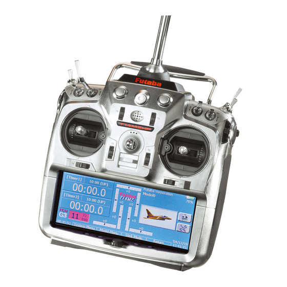
Page 13: Transmitter Controls
Transmitter controls ●Antenna ●Monitor LED (LD,CD,RD) ●Carring Bar ●Volume ●Speaker ●Microphone ●Switch Block ●Switch Block (SC,SD,SG,SH) (SA,SB,SE,SF) ●Slide ●Slide Lever Lever (RST,RS) (LS,LST) ●Stick ●Stick (J3) (J2) (J4) (J1) ●Digital Trim (T1-T6) ●Hook ●Power Switch ●Direct Key ●Rotary Key ●LCD Display (Touch Panel) (S1-S4) Cautions on handling antenna WARNING... -
Page 14: Led Monitor
•Antenna storage • The FUTABA logo blinks red slowly when you When you store the transmitter in the carrying attach the RF module that is different from case, detach the antenna and store it in the antenna the setting. compartment in the transmitter. -
Page 15: Volume (Ld, Cd, Rd)
Slide Lever ●Projection ●LS ●LS ●LST 2. Disconnect the connectors of switches you want to change. LST (Left), RST (right): 3. Use the attached jig (inside stylus) to turn the Outside levers face nuts counterclockwise, this will detach the switches. LS (Left), RS (right): 4. -
Page 16: Digital Trim (T1-T6)
Digital trim Touch Panel/ Rotary Key/ Direct Key This transmitter is equipped with digital trims. Each time you press a trim button, the trim position moves one step. If you continue pressing it, the trim position starts to move faster. In addition, when the trim position returns to the center, the tone will change. -
Page 17: Stick Adjustment
Stick Adjustment Adjustment of Stick Lever Tension You can adjust the tension of stick-levers. Adjustment of the stick lever angle You can make fine adjustments to the angle of a stick lever either inwards or outwards from the ●Retaining Force (J2) ●Stick Tension(J3) (Mode 1) center stick position. -
Page 18: Cf Card Cfdp32M
Be sure to use only Futaba's original CF card, CFDP32M, for the T14MZ transmitter. T14MZ transmitter. Equipment for reading and writing CF cards are available at most electronics * Futaba does not recommend any CF cards other than stores. Futaba's original CF cards. [Important]... -
Page 19: Connector/Plug
Connector/Plug Audio plug (PHONE) Connecting a stereo headphone to this plug, you can enjoy music fi les stored in the CF card. Connector for battery charger (CHG) This is the connector for charging the Lithium Ion battery LT2F2200 that is installed in the transmitter. -
Page 20: Attachment And Detachment Of The Battery
Do not use the transmitter as it is, send it back for a check to the Futaba Service Center. 4. Close and lock the battery cover until you hear a snapping sound. -
Page 21: Rf Module Mz-Fm
RF module MZ-FM Toolbox ●Tool for removing decoration nuts ●Rubber Cap ●Hex. Wrench (1.5mm and 2.5mm) Caution Be sure to turn off the power of the transmitter before you attach or detach the module. You can use the toolbox contained in the set for various adjustment of the transmitter. -
Page 22: Receiver Nomenclature
Receiver nomenclature Before using the receiver, be sure to read the precautions listed in the following pages. Receiver R5014DPS ●Connectors ●Antenna ●B/C ●CH1 12 ●DG1 ●Monitor LED ●DG2 Connector "1 through 12": outputs for the channels 1 through 12 "DG1", "DG2": outputs of DG1 and DG2 channels "B/C": connector for the power and DSC. -
Page 23: Servos
Safety precautions when you install Mounting servos receiver and servos Use a vibration-proof rubber (such as rubber grommet) under a servo when mounting the Warning servo on a servo mount. And be sure that the servo cases do not touch directly to the metal Connecting connectors parts such as servo mount. -
Page 24: Basic Operation
BASIC OPERATION Battery Charging How to charge the Ni-Cd battery NR4F1500 for the receiver Before charging batteries, read the "Cautions for Use the battery charger FBC-32A that is included handling battery and battery charger" in the section in the set. "For your safety". -
Page 25: How To Turn On/Off The Transmitter
How to turn ON/OFF the power of the Warning transmitter Once you turn on the power, never shut off the ® Windows CE is installed as a built-in operating power switch until the power becomes stable system in the T14MZ transmitter. Compared to the (or until the fi... -
Page 26: How To Reset
How to change the frequency/How to set ID The T14MZ system has employed the frequency synthesizer scheme. The T14MZ transmitter will set the frequency of the R5014DPS (PCMG3 ●Reset Button receiver) by the wireless data transmission. When you are using a new PCMG3 receiver and changing the frequency, set ID or frequency by the following instructions. -
Page 27: In Case Of Using Pcm1024, Ppm Receivers
new frequency data is displayed. When Registration of the user's name the frequency setting for the receiver is T14MZ transmitter can register user's name. completed, the LED monitor of the receiver blinks once and the 1CH servo shuttles three times across the neutral position. How to register user's name *A very low power, whose frequency is different from that of the channel frequency, is used to set the frequency of the... -
Page 28: Home Screen
Home screen Here is the home screen and its descriptions. Use your fi nger or included stylus pen to operate the touch screen. User's name Timer Digital trim (T1 to T6, CD) Push this area to call the User's Name Setting screen. •... -
Page 29: Music Playback
Music playback The T14MZ transmitter can play back the ".wma" music fi les stored in the CF (Compact Flash) card. You can listen to them through the built-in speaker or a headphone by the earphone plug. *First, store music fi les from your PC into the WMA folder [Important notice] on the CF card, and then insert the CF card into your Before downloading fi... -
Page 30: Functions Of System Menu
SYSTEM MENU The System Menu sets up functions of the transmitter, this does not set up any model data. ● When the System Menu button is touched, the menu shown below is called. Call the setup screen by pressing the function you want to set up. -
Page 31: Trainer
Trainer Trainer system starting and setting NOTE: This trainer system can be used in the The Trainer function makes it possible for the following manner; instructor to choose which functions and channels 1. In the T14MZ transmitter and a conventional are to be used for instruction, making it possible to transmitter, if the channel order is different. - Page 32 Student mode to confirm this after connecting your trainer 1. Set "Teacher/ Student" button to "Student". cable. 2. Change "ACT/INH" button from "INH" to "OFF" or "ON". 3. Set "12CH/8CH" to "12CH" when the Instructor is using the T14MZ. Otherwise set it to "8CH". Note: In "student mode", only the teacher side can turn on and off the power of the student's transmitter.
-
Page 33: Display
Display LCD screen adjustment and auto power off setting The following LCD screen adjustments and auto power off setting are possible: ● Contrast adjustment ● Auto power off time setting ● Backlighting brightness adjustment ● Background color change ● Touch panel screen position correction ●... -
Page 34: Date & Time
Date and Time Date and time setting (system clock setting) and integrating timer resetting This function adjusts the system clock of the The integrating timer can also be reset. T14MZ transmitter. Perform this setting when you *The integrating timer is displayed on the Home screen. purchase the set and when adjustment is necessary. -
Page 35: User Name
PIN, none of the settings can be changed. In this A PIN can also be set to protect the set data or case, the system must be reset by the Futaba Service Center. user name. ● Touch the [User Name] button at the System Menu to call the setup screen shown below. -
Page 36: Switch
Switch Toggle switch type setting (Setting when the switch was replaced.) If you modify the location of the switches on the right and left (top) of the transmitter, you should be sure to re-assign functions to the switches for proper operation. A “Lock”... -
Page 37: Hw Reverse
H/W Reverse Stick, switch, trim lever, and knob operation direction reversal (Hardware reverse) Note: This setting reverses the actual operation This function reverses the operation signal of the signal, but does not change the display of sticks, switches, trimmer levers, and knobs. the indicators on the display. -
Page 38: Information
Information Displays the program version, CF card information, and product ID. T h e T 1 4 M Z s y s t e m p r o g r a m v e r s i o n *When the CF card is not inserted, the CF card information is not displayed. -
Page 39: Model Basic Setting Procedure
MODEL BASIC SETTING PROCEDURE Airplane/glider basic setting procedure 1. Model addition and call Initial setting assigns 1 model to the T14MZ transmitter. The Model Select function of the Linkage Menu is used to add models and to call models which are already set. This is convenient when calling a model after its name has been registered. - Page 40 4. Throttle cut setting The preset elevators and flaps (camber flap, brake fl ap) offset amount can be activated by a switch. Throttle cut can be performed with one touch by a The offset amount of the aileron, elevator, and fl ap switch without changing the throttle trim position.
-
Page 41: Helicopter Basic Setting Procedure
Helicopter basic setting procedure 1. Model addition and call Default setting assigns 1 model to the T14MZ. To add new models or to call a model already set, use the Model Select function of the Linkage Menu. 3. Flight condition addition The transmitter can install up to eight flight conditions per model. - Page 42 ● Swash plate correction (Except H-1 mode) 4. Fuselage linkage Operation of the swash plate near the hovering Connect the throttle rudder, ailerons, elevators, point can be corrected by swash AFR function pitch, and other rudder linkages in accordance with correction mixing.
- Page 43 ●Throttle hold curve adjustment manipulation, the Auto mode can be set. The throttle hold curve is used when performing When you want to adjust the servo speed, adjust auto rotation dives. [Speed]. Confi rm that the rate of the slowest position (0%) of the stick is 0% (initial setting).
- Page 44 1. A curve setting example is shown below. 10. Gyro sensitivity and mode switching A. Pitch to RUD mixing curve (Normal) The gyro sensitivity and mode switching Use the hovering system and set this curve to function is dedicated gyro mixing of the Model match take off and landing and vertical climb at Menu, and can be set for each condition.
-
Page 45: Receiver And Servos Connection
Receiver and servos connection Connect the receiver and servos in accordance with the connection diagram shown below. Always read [Precautions when mounting the receiver and servos] of [Before using]. When mounting the receiver and servos to the fuselage, connect the necessary points in accordance with the kit instruction manual. Receiver and servos connection diagram ●Always connect the necessary number of servos. -
Page 46: Servo Connection By Model Type
Servo connection by model type The T14MZ transmitter channels are automatically assigned for optimal combination according to the type selected with the Model Type function of the Linkage Menu. The channel assignment (initial setting) for each model type is shown below. Connect the receiver and servos to match the type used. *The set channels can be checked at the Function screen of the Linkage Menu. - Page 47 ●Ailevator 1AIL 2AIL 2AIL+1FLAP 2AIL+2FLAP RX CH Glider Glider Glider Glider Airplane Airplane Airplane Airplane Elevator Elevator Elevator Elevator Elevator Elevator Elevator Elevator Elevator Elevator Elevator Elevator Elevator2 Elevator2 Elevator2 Elevator2 Elevator2 Elevator2 Elevator2 Elevator2 Elevator2 Elevator2 Elevator2 Elevator2 Rudder Rudder Rudder Rudder Rudder Rudder Rudder Rudder Rudder Rudder Rudder Rudder Aileron Aileron Aileron Aileron Aileron Aileron Aileron Aileron Aileron Aileron Aileron Aileron Throttle Motor...
- Page 48 ●Tailless wing 2AIL 2AIL+1FLAP 2AIL+2FLAP RX CH Glider Glider Glider Airplane Airplane Airplane Rudder Rudder Rudder Rudder Rudder Rudder Rudder Rudder Rudder Rudder2 Rudder2 Rudder2 Rudder2 Rudder2 Rudder2 Rudder2 Rudder2 Rudder2 Throttle Motor AUX1 Throttle Motor AUX7 Throttle Motor AUX6 Aileron Aileron Aileron Aileron Aileron Aileron Aileron Aileron Aileron Aileron2 Aileron2 Aileron2 Aileron2 Aileron2 Aileron2 Aileron2 Aileron2 Aileron2 Gear...
- Page 49 Helicopter ●When a receiver other than the PCM-G3 type is used, only the shaded part of the table at H-4 Swash All Other the left is valid. ●VC1~4 are virtual channels with no receiver Throttle Throttle output. For more information, see the Rudder Rudder description of the Function menu of the...
-
Page 50: Functions Of Linkage Menu
FUNCTIONS OF LINKAGE MENU The Linkage Menu is made up of functions The functions which can be selected depend on which perform model addition, model type the model type. A typical menu screen is shown selection, frequency setting, end point setting, and below. -
Page 51: Servo Monitor
Servo Monitor Servo Test & Graph Display / Displays servo positions. This is used for testing servo movement. Touch move from “Moving Test” to “Neutral Test” “Moving Test” (repetition mode) or “Neutral automatically. Next touch the “Test” on/off button Test” (fixed position mode) depending on which to start testing your servos. -
Page 52: Model Select
Model Select The Model Selection function performs model addition, call, deletion, copy, and model name setting. This function is used to load the settings of the can be as long as 32 characters, and the model name desired model into the T14MZ’s memory. always appears in the display screen. -
Page 53: Model Type
Model Type This function selects the model type from among airplane, helicopter, and glider. Note: The Model Type function automatically Seven types of main wings and three types selects the appropriate output channels, control of tail wings are available for airplanes. Seven functions, and mixing functions for the chosen model swash types are available for helicopters. - Page 54 ●Model type selection Model type Select the model type f r o m a m o n g a i r p l a n e , helicopter, glider, and motor glider. (Airplane, glider) (Helicopter) ●Wing type selection (1/2) ●Swash type selection ●Wing type selection (2/2) Helicopter swash type Select from among H-1, H-2, H-4,...
-
Page 55: Picture
Picture A picture can be pasted for each model. (Simplifies identification of the model data during screen operation.) A photograph of the model taken with a digital When a picture is pasted, it is displayed as the camera or other file can be pasted as the screen following screen image: ●Model Select screen display data for each model. -
Page 56: Sound
Sound Sound recording and playback. Sounds recorded with the microphone built into fi les can be switched each time the same switch is the transmitter and audio fi les (.wav) saved on the operated. This can be used when playing back the CF card from the PC can be played back when name of maneuvers, etc. - Page 57 5. Select the switch and its ON direction at the Assignment of audio fi les to switches Switch select screen. *Audio fi les can be saved to CF card beforehand. (For a detailed description of the selection method, 1. Touch the fi le button of the No. you want to see "Switch setting method"...
-
Page 58: Frequency
Frequency Frequency Band (frequency) setting, modulation mode setting, receiver ID code setting. Frequency setting Modulation mode selection The T14MZ transmitter uses a synthesizer With the T14MZ, 3 modulation modes (PCM-G3/ system. Its frequency can be changed within the PCM1024/PPM (FM)) can be selected. Select the range of the frequency band of the module used. -
Page 59: Function
CH 6, CH 7through CH 9 and CH 10 through CH 12 already preset. If you would like, on the function- work simultaneously. Futaba recommends that you setting screen of the linkage menu, you can freely use the standard optimized default combinations... - Page 60 ATL mode: ATL operation mode. Reverse is also Trim change possible. 1. Touch the Trim button to call the Trim setup CTRM mode: Maximum change near center by screen. center trim operation 2. The following items can be set at the Trim ●...
-
Page 61: Sub-Trim
Sub-Trim Setting of neutral position of each servo. The Sub-Trim function is used to set the servo neutral position, and may be used to make fine adjustments to the control surface after linkages and pushrods are hooked up. When you begin to set up a model, be sure that the digital trims are set to their center position. -
Page 62: Servo Reverse
Servo Reverse Use to reverse the throw direction. Servo Reverse changes the direction of an that control multiple servos, it may be confusing individual servo’s response to a control stick to tell whether the servo needs to be reversed or a movement. -
Page 63: Fail Safe
Fail Safe Sets the servos operating position when transmitter signals can no longer be received or when the receiver battery voltage drops. The Failsafe function may be used to set up positions failsafe may be released by operating a predefi ned that the servos move to in the case of radio interference. -
Page 64: End Point (Atv)
Sets the travel, limit point, and speed of each servo. End Point (ATV) The End Point function adjusts the left and right NOTE: The indicators on the screen display actual servo throw of the each channel. The center position of the servo throws, generates differential throws, and indicator is based on the Sub-Trim settings. -
Page 65: Throttle Cut (Airplane/Helicopter Only)
Throttle Cut Stops the engine safely and easily.(airplane and helicopter only) Throttle cut provides an easy way to stop the engine, by fl ipping a switch with the throttle stick at idle. The action is not functional at high throttle to avoid accidental dead sticks. -
Page 66: Idle Down (Airplane/Helicopter Only)
Idle Down Lowers the engine idling speed.(airplane and helicopter only) The Idle Down function lowers the engines idle by fl ipping a switch with the throttle stick at idle. The action is not functional at high throttle to avoid accidental dead sticks. The switch’s location and direction must be chosen, as it defaults to NULL. -
Page 67: Swash (Helicopter Only)
Swash Swash operation linkage correction function.(helicopter only) Neutral Point Swash AFR At your linkages, if the servo horn deviates Swash AFR function reduces/increases/reverses from a perpendicular position at neutral, the the rate (travel) of the aileron, elevator and linkage compensation functions in this menu collective pitch functions, by adjusting or reversing may not compensate effectively. - Page 68 Mixing Rate Linkage Compensation This compensation mixing is used to correct the This compensation mixing is used to correct the tendency of the swash-plate for each control near tendency of the swash-plate for pitch control at low the hovering point. The following compensation pitch and high pitch.
-
Page 69: Timer
Timer Timer setting and lap time display. The Timer function may be set for any desired time, Each timer may be set for count-down or count i.e. engine run time, specifi ed times for competitions, up operation with a target time. Also Split Time etc. -
Page 70: Dial Monitor
Dial Monitor LDisplays the position of the dials, slider levers, and digital trim. Digital Trim Position display (T1-T6, CD) The Dial Monitor displays the current position and the operation step amount of each Digital Trim. VR and slide lever position display (LST, LS, LD, RD, RS, RST) Displays the current position (black ) and last operating position (green ) of the VRs and slider... -
Page 71: Data Reset
Data Reset Model memory setting data reset. (by item) This function is designed to allow you to reset Model menu setting: selected portions or all of the settings saved in Resets all the functions in the Model Menu the active model memory. You may individually except Condition Select. -
Page 72: Common Functions
MODEL MENU (COMMON FUNCTIONS) Note: The T14MZ is designed so that the airplane This section describes the AFR, program mixing, and glider (including EP glider) model types are and other functions common to all model types. compatible with fuselages of similar type wings. Before setting the model data, use the Model This section outlines the relationship between the Type function of the Linkage Menu to select the... -
Page 73: Condition Select
Condition Select Flight conditions addition, deletion, copy, condition renaming, and condition delay can be set. [All model types] when there are sudden changes in the servo The functions in the Model Menu can be used by positions and when there are variations in switching the settings of up to 8 flight conditions the operating time between channels during by using the Condition Select function to add fl... -
Page 74: Condition Hold
● Touch the [Delay] button on the Condition Select screen to call the Condition Delay screen shown below. ● Return to Condition Select screen (Currently selected condition name) ●Adjustment buttons ●Group/single mode switching (Gr./Sngl) (For a description of the operation method, see the description at the back of this manual.) Condition delay setting 1. -
Page 75: Afr (D/R)
AFR (D/R) The rudder angle and curve of each operation function can be set. A D/R curve which can be switched by switch, etc. can also be added. [All model types] AFR function is used to adjust the throw and Setting method operation curve of the stick, lever, and switch ●... - Page 76 Setting method Dual Rate setting ● Touch the [D/R] button from the AFR (D/R) Up to 6 dual rates can be set for each condition. screen of the function (ailerons, elevators, *D/R (Dual Rate) is set for each condition, and is not etc.) whose dual rate you want to set.
-
Page 77: Program Mix
Prog. Mixes Program mixing which can be freely customized. Up to 10 mixings can be used for each condition. [All model types] Programmable mixing may be used to correct have mixing remaining on all the time. undesired tendencies of the aircraft, and it may also be Offset-type mixing applies a fixed offset or preset used for unusual control confi... - Page 78 ●Trim mode ON/OFF setting Setting methods 1. To turn the trim mode ON/OFF, touch the Trim ●Group/single mode selection button on the screen. Activating functions for only the selected *When mixing includes master side trim, set the Trim button conditions: to [ON].
-
Page 79: Fuel Mixture
Fuel Mixture Dedicated mixing used in needle adjustment of engines which use a fuel mixture control carburetor. [Airplane, helicopter] This function is dedicated mixing used in needle *The needle channel is assigned to CH9 as a default. adjustment of an engine that uses a fuel mixture control carburetor. -
Page 80: Airplane/Glider/Ep Glider Functions
MODEL MENU (AIRPLANE/GLIDER FUNCTIONS) The dedicated mixings, etc. usable when condition by switch or stick position, use the airplane, glider, or EP glider model type is Condition Select function to add fl ight conditions. selected are displayed in this Model Menu (Up to 8 conditions can be used) Note: The T14MZ is designed so that the airplane functions section. - Page 81 ●Camber Mix ●V-tail This mixing adjusts the camber and corrects the This function adjusts the elevators and rudder of elevators. [Airplane/glider, 2 ailerons or more] V-tail models. [Airplane/glider, V-tail specifi cations] ●ELE to Camber ●Ailevator This mixing is used when you want to the mix This function adjusts the elevators and ailerons of camber fl...
-
Page 82: Ail Differential
AIL Differential [Airplane/glider, 2 ailerons or more] The left and right ailerons differential can be adjusted independently. The differential rate can also be adjusted according to the flying state by setting a fi ne tuning VR. ●A fi ne tuning curve can be set. Note: Aileron up/down setting (%) reset is +100% when reset when setting is +, and -100% when reset when setting is -. -
Page 83: Flap Setting
Flap setting [Corresponding model type]: Airplane/glider, 2 fl aps or more The up/down travel of each fl ap (camber fl aps: FLP1/2, brake flaps: FLP3/4) can be adjusted independently at each servo according to the wing type. ● The operation reference point of each fl ap can be offset The camber flaps of a 4-flap model can be mixed with the brake fl... -
Page 84: Ail To Camber Flp
AIL to Camber FLP [Corresponding model type]: Airplane/glider, 2 ailerons + 2 fl aps or more This mixing operates the camber fl aps (FLP1/2) in the aileron mode. When the aileron stick is manipulated, the ailerons and camber flaps perform aileron operation simultaneously and the operation characteristic of the roll axis is improved. -
Page 85: Ail To Brake Flp
AIL to Brake FLP [Corresponding model type]: Airplane/glider, 4 fl aps or more This mixing operates the brake fl aps (FLP3/4) in the aileron mode. When the aileron stick is manipulated, the aileron and brake flaps perform the aileron operation simultaneously and the operation characteristic of the roll axis is improved. -
Page 86: Ail To Rud
AIL to RUD [Corresponding model type]: Airplane/glider, general Use this mixing when you want to mix the rudders with aileron operation. ● A mixing curve can be set. ● Mixing during fl ight can be turned ON/OFF by setting a switch. (Always ON at NULL setting) ●... -
Page 87: Airbrake To Ele
Airbrake to ELE [Corresponding model type]: Airplane/glider, general This mixing is used when you want to mix the elevators with airbrake (spoiler) operation. It raises the elevators to correct for drooping of the AIRBRAKE nose during airbrake operation. *This function does not operate when airbrake is not assigned at the Function menu in the Linkage Menu. -
Page 88: Rud To Ail
RUD to AIL [Corresponding model type]: Airplane/glider, general on the mixing curve. When the memory mode is This function is used when you want to mix exited, the memorized points are automatically the ailerons with rudder operation. It is used refl... -
Page 89: Camber Mix
Camber Mix [Corresponding model type]: Airplane/glider, 2 ailerons or more ● Mixing during fl ight can be turned ON/OFF by This function adjusts the AFR (D/R) rate setting a switch. (Always ON at NULL setting) of camber operation which operates the wing ●... - Page 90 ● Camber AFR(D/R) screen call Setting method Touch the Camber AFR button to call the setup ● Touch the "INH" button and set the function to ACT screen. (For a description of the setup method, (ON). see the description at the back of this manual.) ●...
-
Page 91: Ele To Camber
ELE to Camber [Corresponding model type]: Airplane/glider, 2 ailerons or more ● A mixing curve can be set. This function is used when you want to mix ● Mixing during fl ight can be turned ON/OFF by the camber flaps with elevator operation. When setting a switch. -
Page 92: Camber Flp To Ele
Camber FLP to ELE [Corresponding model type]: Airplane/glider, 2 ailerons + 1 flap or more This mixing is used to correct changes (elevator direction) generated when the camber fl aps (speed fl aps) are used. ● The elevator servos up side/down side rate can be adjusted. -
Page 93: Butterfl Y
Butterfl y [Corresponding model type]: Glider, 2 ailerons or more ● Mixing during fl ight can be turned ON/OFF by This function allows powerful brake operation setting a switch. (Always ON at NULL setting) by simultaneously raising the left and right ●... - Page 94 ● Touch the ELE correction rate buttons and adjust the rates with the adjustment buttons displayed on the screen. ([ELE Setup] screen) ● Servo speed setting ● Mixing curve setting (For a description of the setting method, see the (For a description of the curve setting method, see the description at the back of this manual.) description at the back of this manual.) FLP 4...
-
Page 95: Trim Mix 1/2
Trim Mix 1/2 [Corresponding model type]: Glider, 2 ailerons or more These functions call the ailerons, elevators, and Example fl aps (camber fl aps, brake fl aps) trim offset rates 1. Touch the ACT button and set the trim mix function preset according to the fl... - Page 96 ● Group/single mode switching ● When using a fine tuning VR, touch this (Gr./Sngl) button to call the <Switch> screen. ( F o r m o r e i n f o r m a t i o n , s e e t h e description at the back of this manual.) ●Return to Model Menu (Trim mix setup page 2/2)
-
Page 97: Airbrake
Airbrake [Corresponding model type]: Airplane, general This function is used when an air brake is Setting example for F3A and other fl aperon necessary when landing or diving, etc. specifi cations The preset elevators and flaps (camber flap, (When 2 ailerons model type selected) brake flap) offset amount can be activated by a (Page 1/2) switch. - Page 98 ● Group/single mode switching ● When using a fine tuning VR, touch this (Gr./Sngl) button to call the <Switch> screen. ( F o r m o r e i n f o r m a t i o n , s e e t h e description at the back of this manual.) ●Return to Model Menu (Airbrake setup screen 2/2)
-
Page 99: Gyro
● Touch the ACT button of the rate to be used, and set the function to ACT ([ON] or [OFF]). ● When a Futaba GYA gyro is used, when [GY] type is s elected, the sensitivity set value is directly read in both the AVCS and NOR modes. -
Page 100: V-Tail
V-tail [Corresponding model type]: Airplane/glider, V-tail This function let’s you adjust for left and right rudder angle changes at elevator and rudder operation of a V-tail airplane. V-TAIL V-tail is when 2 servos are used together to control rudder movement as Elevators. In addition to each rudder side moving up and down together, each side moves in opposite directions when moving as Elevators. -
Page 101: Ailevator
[Corresponding model type]: Airplane/glider, V-Tail Ailevator (Effective only when 2 servos used at the elevators) This function improves the operating performance of the roll axis by operating the elevators as ailerons. Ailevator is where each elevator in a standard (conventional) or v-tail moves independently, like ailerons on a wing. -
Page 102: Winglet
Winglet [Corresponding model type]: Airplane/glider, winglet This function adjusts the rubber left and right rudder angle of winglet specifi cations fuselages. Winglets are used to improve the efficiency of aircraft lowering the lift-induced drag caused by wingtip vortices. The winglet is a vertical or angled extension at the tips of each wing. -
Page 103: Motor
Motor [Corresponding model type]: EP glider, general by setting the switch to OFF before operation is This function lets you set the operation speed fi nished. When you want to reset 1 time operation, when the motor of a F5B or other EP glider is set the ACT button to [INH] and then reset it to started by switch. -
Page 104: Rud To Ele
RUD to ELE [Corresponding model type]: Airplane, general convenient at mixing curve setting. When memory This function is used when you want to mix operation (switch operation) is performed with elevator operation with rudder operation. It is used correction rudder applied in the Memory Mode, to correct undesirable tendencies when rudder is the stick position at that time is displayed on the applied in roll maneuvers, knife edge, etc. -
Page 105: Snap Roll
Snap Roll [Corresponding model type]: Airplane, general This function selects the switch and rate (Example) Setting example for F3A adjustment of each rudder, (ailerons, elevators, or ● Mode: [Master] fl aps) when a snap roll is performed. ● Safety SW: [SW-G] (Safety measure) ●... -
Page 106: Multi Engine
Multi Engine [Corresponding model type]: Airplane, general ● The throttle down offset rate can be set for each This function lets you adjust the throttle when throttle channel. Idle down operation is linked to using a multi engine airplane with up to 4 engines. the switch set with the Idle Down function of the The Throttle Cut function, Idle Down function, Linkage Menu. -
Page 107: Helicopter Functions
MODEL MENU (HELICOPTER) This section contains information on the fuselage beforehand. If you later change model commands that apply to helicopters only. For types, all settings will be lost. instructions on Airplanes and Sailplanes, refer Also, add flight conditions at the Condition to the sections pertaining to those aircraft. -
Page 108: Pit Curve
PIT Curve/Pitch Trim PIT Curve This function adjusts the pitch operation curve the 3 points or 5 points specifi ed to create a curve, a simple and smooth curve can be created by selecting the curve type for each fl ight condition for the optimal fl ight state and reducing the number of input points to 3 or 5, and then relative to movement of the throttle stick. - Page 109 Setting method ● Group button: When you also want to input the [Fine Tuning]: When pitch trim is used, a curve with same setting contents at other conditions, perform pitch trim adjustment added is also displayed. setting in the group mode (initial setting). In this [All Cond.]: Displays the pitch curve of all the case, the same contents are input to the other conditions.
- Page 110 Hovering pitch trim High Pitch/Low Pitch Trim The Hovering Pitch function trims the pitch near High Pitch/Low Pitch Trim is the pitch servo the hovering point. Normally, it is used with the high side and low side trim function. hovering condition. The hovering pitch can be fi ne Setting method tuned for changes in rotor speed accompanying ●...
-
Page 111: Thr Curve
Adjustment to the curve you want to use is possible by using the 14MZʼs powerful Curve Edit Function. Up to 17 curve ● Touch the [THR Curve] button in the Model Menu to call the setup screen shown below. - Page 112 Curve setting examples actually creating a curve, enter the data specified The curves shown below were created by using per the fuselage (or the reference value). the Line mode and inputting the data of the 5 points 0% (low side), 25%, 50% (center), 75%, 100% *For a description of the curve creation method, see the (high) side at each condition.
-
Page 113: Acceleration
Acceleration Mixing Example of acceleration function use This function is used to adjust the pitch and the throttle rise characteristic at acceleration/ ●When used at pitch, the Acceleration deceleration operation. An acceleration function function is effective when you want to quicken the response of the fuselage at 3D which temporarily increases the pitch and throttle fl... -
Page 114: Throttle Hold
Throttle Hold Example of use This function sets the throttle cut position at auto rotation dive. The throttle position can also be ● Since Throttle Hold has 2 modes (Cut) and set to an idling position separate from the throttle (Idle), using it in the Idling mode during t r a i n i n g a n d i n t h e C u t m o d e w h e n cut position. -
Page 115: Swash Mix
Swash mixing Example of use The swash mix function is used to correct the swash plate in the aileron (roll) direction and ● As an example, use swash mixing to correct elevator (cyclic pitch) corresponding to each undesirable tendencies in the roll direction operation of each condition. -
Page 116: Throttle Mix
Throttle mixing This function corrects slowing of engine When correction is necessary, touch the mixing speed caused by swash plate operation at aileron corresponding to the mixing that needs correction or elevator operation. The method of applying to call the curve setup screen, and then correct the clockwise or counterclockwise torque when slowing. -
Page 117: Pit -> Needle
PIT to Needle mixing This mixing is used when the engine is equipped with needle control or other fuel-air mixture adjustment. A needle curve can be set. An acceleration function which temporarily increases needle operation at throttle stick acceleration/deceleration operation can be set. The rise characteristic of the needle servo at acceleration and deceleration operation can be adjusted. -
Page 118: Pit -> Rud
PIT to RUD mixing (Revolution mixing) Use this mixing when you want to suppress the However, when a GY Series or other heading reaction torque generated by main rotor pitch and hold gyro is used, since correction is performed by speed changes at pitch operation. -
Page 119: Gyro
Gyro mixing This function used to adjust gyro sensitivity. The Setting example sensitivity and operation mode (Normal mode/GY Normally, it is convenient to preset high ● mode) can be set for each condition. sensitivity (Rate 1) and low sensitivity (Rate 2) when either the AVCS mode or Normal *Sensitivity setting is assigned to CH3. -
Page 120: Governor
Governor mixing This is used to switch the RPM of the helicopters *When using the Fuel Mixture function, the mixture servo is controlled from the governor. When transmitting the head. Up to 3 rates can be set for each condition. mixture curve data from the transmitter to the governor, the *The governor is used by connecting the governor speed governor AUX (m.trm) connector must be connected to CH8... -
Page 121: Common Operations Used In Function Setup Screen
Common operations used in function setup screen This section describes the functions often used at the function setup screen. Refer to it when setting each function. Operations related to fl ight conditions Operations related to VR tuning Group/single mode switching (Gr./Sngl) Fine tuning VR setting W h e n s e t t i n g m u l t i p l e f l i g h t ●... - Page 122 Operations related to servo speed Servo speed setting (2) Servo speed setting (1) The speed at each operation (including flight condition switching) can be adjusted. The servos operate smoothly at a constant speed corresponding to the set speed. The operation speed (In Speed) and the return speed (Out Speed) [Setting method] can be set individually.
- Page 123 Curve setting operation This section describes the setting procedure of curves which are used with the AFR function and each mixing function. Curve type selection When the curve type select button on the mixing function screen or other screen is touched, the setup screen shown below is called.
- Page 124 EXP1 curve adjustment (EXP1 curve) Rate A and Rate B can be adjusted separately or simultaneously. The EXP curves rate (EXP A, EXP B) can also be adjusted separately or simultaneously. [Setting modes] *[Separate] mode: Rates are adjusted separately. *[Combined] mode: Rates are adjusted simultaneously.
- Page 125 Line and spline curve adjustment (Line curve) Line curves or spline curves of up to 17 points can be used. (Initial value: 9 points) The set points can be freely increased, decreased, and offset. Curves which are symmetrical to the left and right of center can also be set.
- Page 126 Switch selection method The various functions used in the T14MZ can be selected by switch. The switch (including when stick, trim lever, or VR are used as a switch) setting method is common to all functions. Switch selection When the switch select button at a mixing function screen or other screen is touched, the selection shown below is called.
- Page 127 Operation modes The operation modes when stick, trim lever or VR are selected are described below. Change the operation mode by touching the Mode and Type buttons. Linear hysteresis mode When shifting the ON/OFF point This setting method selects function ON/OFF The ON/OFF and hysteresis (dead band) based on the set point.
Need help?
Do you have a question about the 14MZ and is the answer not in the manual?
Questions and answers