Table of Contents
Advertisement
Quick Links
Advertisement
Table of Contents

Related Manuals for Delta Electronics Ethernet Communication Module DVPEN01-SL


Summary of Contents for Delta Electronics Ethernet Communication Module DVPEN01-SL
- Page 1 DVPEN01-SL Ethernet Communication Module Application Manual...
-
Page 3: Table Of Contents
Numbering of Left-Side Extension Modules ...12 SETTING UP SOFTWARE ...13 Setting up Communication & Searching for Modules...13 Basic Settings ...16 Network Settings ...18 Setting up E-Mails ...20 Data Exchange...22 DVP-PLC Application Manual Ethernet Communication Module DVPEN01-SL is correctly grounded in order to prevent electromagnetic interference. - Page 4 Ethernet Communication Module DVPEN01-SL IP Filter ... 23 Static ARP Table ... 24 Setting up Password... 25 Returning to Default Setting ... 26 5.10 Export & Import of DVPEN01-SL Files ... 27 5.11 Recording IP Address ... 28 APPLICATION EXAMPLES... 29 Setting up IP and Communicating through WPLSoft...
-
Page 5: Introduction
Number of ports Transmission cable Environment Item Noise immunity Environment DVP-PLC Application Manual Ethernet Communication Module DVPEN01-SL Specification RJ-45 with Auto MDI/MDIX 1 Port IEEE802.3, IEEE802.3u Category 5e 10/100 Mbps Auto-Detect ICMP, IP, TCP, UDP, DHCP, SMTP, NTP, Modbus TCP... -
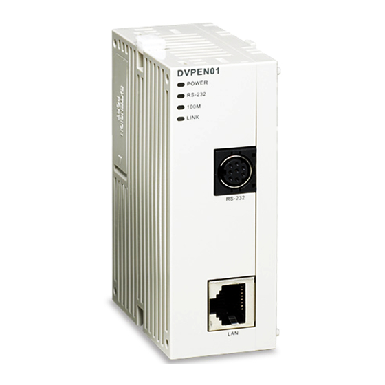
Page 6: Product Profile & Outline
Ethernet Communication Module DVPEN01-SL Item Vibration/ Shock Resistance Electrical specifications Item Power supply voltage Power consumption Insulation voltage Weight (g) Product Profile & Outline Dimension Product Profiles 1. Model name 2. Extension port to connect device 3. Extension port to connect extension module 8. RS-232 connection port 4. -
Page 7: Led Indicators
Connect DVPEN01-SL to other extension modules To connect DVPEN01-SL with the other extension module, lift the extension clip of the extension module by a screwdriver and open the side cover. DVP-PLC Application Manual Ethernet Communication Module DVPEN01-SL Color Green Communication status of the series port... -
Page 8: Control Register (Cr)
Ethernet Communication Module DVPEN01-SL Connect DVPEN01-SL to the Network Connect DVPEN01-SL to the Ethernet Hub by twisted pair cable CAT-5e. DVPEN01-SL has Auto MDI/MDIX function; therefore, DVPEN01-SL does not need to use a crossing cable between the PC and DVPEN01-SL. - Page 9 Modbus TCP status Modbus TCP #118 #117 destination IP DVP-PLC Application Manual Ethernet Communication Module DVPEN01-SL Content b0 ~ b7: Current status of E-Mail 2 b8 ~ b15: Current status of E-Mail 1 b0 ~ b7: Current status of E-Mail 4 b8 ~ b15: Current status of E-Mail 3 Filled in by the user, and it will be send by E-mail.
-
Page 10: Explanations On Cr
Ethernet Communication Module DVPEN01-SL Attribute #119 Modbus TCP data length Setting up the data length for Modbus TCP transaction #219 ~ #120 Modbus TCP data buffer Data buffer of Modbus TCP for storing sending/receiving data #248 ~ #220 Reserved #251... - Page 11 ID is set as “0”, the value in CR#25 and #26 will be regarded as the destination IP. CR# 29 ~ 48 : Data Transmission Buffer Explanations: DVP-PLC Application Manual Ethernet Communication Module DVPEN01-SL E-Mail status Fail to connect to SMTP-Server Incorrect recipient E-Mail address SMTP-Server communication error Exceeding the max.
- Page 12 Ethernet Communication Module DVPEN01-SL Storing the data to be transmitted to the remote MPU. CR# 49 ~ 68 : Data Receiving Buffer Explanations: Storing the data received from the remote MPU. CR#81: Read Address for Data Exchange Explanations: Setting up manually the Modbus address of the register for Slave data exchange. Only register address is allowed (e.g.
- Page 13 When the CR value is set as “1”, Modbus TCP will be triggered. After the data transmission is completed in Modbus TCP mode, the CR value will automatically be reset to “0”. Please trigger by differential instructions. DVP-PLC Application Manual Ethernet Communication Module DVPEN01-SL 8-bit mode. normal status; when the CR value IP setting in progress.
-
Page 14: Numbering Of Left-Side Extension Modules
Ethernet Communication Module DVPEN01-SL CR#116: Modbus TCP Status Explanations: Displaying the current communication status of Modbus TCP mode. When the CR value is set as”0” the data have not yet been received; when the CR value is set as “1”... -
Page 15: Setting Up Software
DVPEN01-SL is set up by UDP port 20006; therefore, you have to be aware of the relevant settings of the firewall. Setting up Communication & Searching for Modules 1. Communication settings • Open WPLSoft in your PC and click on “Communication Setting”. • Select “Ethernet” as the transmission type. DVP-PLC Application Manual Ethernet Communication Module DVPEN01-SL... - Page 16 Ethernet Communication Module DVPEN01-SL 2. Auto-search • Press “Auto-Search” (circled) to search for every DVPEN01-SL in the network and display them in the left column. • Move the cursor to the module you would like to set up. Double click it to enter the setup page.
- Page 17 IP list. Press “OK" to start the searching. • The DVPEN01-SL searched is displayed in the left column. Move the cursor to the module you would like to set up. Double click it to enter the setup page. DVP-PLC Application Manual Ethernet Communication Module DVPEN01-SL...
-
Page 18: Basic Settings
Ethernet Communication Module DVPEN01-SL 4. Opening DVPEN01-SL setup page by RS-232` • Select “RS232" as the transmission type in communication setting. You will have to designate a communication port. When DVPEN01-SL is searched by RS-232, you do not need to set up the parameters (i.e. - Page 19 Most adjacent time zones are exactly one hour apart, and by convention compute their local time as an offset from Greenwich Mean Time (see also UTC). Standard time zones can be defined by geometrically subdividing the Earth's spheroid into 24 lunes (wedge-shaped DVP-PLC Application Manual Ethernet Communication Module DVPEN01-SL...
-
Page 20: Network Settings
Ethernet Communication Module DVPEN01-SL sections), bordered by meridians each 15° of longitude apart. The local time in neighboring zones is then exactly one hour different. However, political and geographical practicalities can result in irregularly shaped zones that follow political boundaries or that change their time seasonally (as with daylight saving time), as well as being subject to occasional redefinition as political conditions change. - Page 21 Ethernet Communication Module DVPEN01-SL • Enter 192.168.0.1 into IP address. Click on “OK” to complete the IP address setting of the PC. 2. Setting up DVPEN01-SL Network • IP configuration: There are two types of IP, static IP and DHCP.
-
Page 22: Setting Up E-Mails
Ethernet Communication Module DVPEN01-SL Static DHCP • IP address: IP address is the location of the equipment in the network. Every equipment connected to the network has to have an IP address. Incorrect IP address will result in connection failure on the equipment or even other equipment. - Page 23 3. E-Mail of Sender: Maximum 63 English characters are allowed. 4. E-mail of Recipient: You can enter 4 E-Mail addresses. One mail can be sent to 4 addresses (max. 63 English characters are allowed). DVP-PLC Application Manual Ethernet Communication Module DVPEN01-SL...
-
Page 24: Data Exchange
Ethernet Communication Module DVPEN01-SL 5. Select recipients: After you have set up all the parameters for the E-Mail, you will need to select recipients. The E-Mail will be sent to the designated recipients when the E-Mail is triggered. To trigger E-Mail, set the value is CR#3 ~ CR#6 as “1”. -
Page 25: Ip Filter
IP filter is used for restricting the connection of the network in case some uncertain IP will cause errors. Only the IP set within a certain range can establish a connection. Other IPs will be rejected. Setting up IP filter DVP-PLC Application Manual Ethernet Communication Module DVPEN01-SL... -
Page 26: Static Arp Table
Ethernet Communication Module DVPEN01-SL 1. Enable IP Filter Function: Check the box to enable IP filter. 2. IP: IP addresses that are allowed to establish connections. Maximum 8 IPs are allowed. 3. Netmask: The subnet of the IP is allowed to establish a connection. To see whether the destination IP is allowed, conduct bitwise AND operations between the allowed IP and subnet mask and destination IP and subnet mask. -
Page 27: Setting Up Password
Setting up Password To prevent the set values in DVPEN01-SL from being modified, you can set up password to lock the settings in DVPEN01-SL. Setting up DVPEN01-SL password DVP-PLC Application Manual Ethernet Communication Module DVPEN01-SL... -
Page 28: Returning To Default Setting
Ethernet Communication Module DVPEN01-SL 1. Modify: Check the box to modify the password. 2. New Password: Maximum 4 characters are allowed. Leave the column “blank” to disable the password protection function. 3. Confirm Password: Enter the new password again. 4. See “Application Examples Section 6.4” for more details. -
Page 29: 5.10 Export & Import Of Dvpen01-Sl Files
Ethernet Communication Module DVPEN01-SL Check “Default Setting” box and click on “Yes”. Note: If you set up DVPEN01-SL by RS-232, you can return the setting to default setting whether the password is locked or not. It takes approximately 10 seconds to return to default setting, so DO NOT switch off the power within the 10 seconds. -
Page 30: 5.11 Recording Ip Address
Ethernet Communication Module DVPEN01-SL 1. Export: Save all the settings of DVPEN01-SL into *.eni files. The exported files do not include the password. 2. Import: Select a file and the file will be imported to all the settings. 5.11 Recording IP Address When DVPEN01-SL is searching for a designated IP, there is a list for you to directly select and designate a module to be searched. -
Page 31: Application Examples
(4) Connect the PC and DVPEN01-SL by RJ-45 cable. Note: Both PC and DVPEN01-SL have to adopt static IP. 1. The connection 2. Open "Communication Setting” in WPLSoft. 3. Select “Ethernet” and press "OK”. DVP-PLC Application Manual Ethernet Communication Module DVPEN01-SL DVPEN01 DVP-PLC... - Page 32 Ethernet Communication Module DVPEN01-SL 4. Click on “Auto-Search” icon to search for all DVPEN01-SL modules in the network. 5. Designate a DVPEN01-SL and double click it to open the setup page. DVP-PLC Application Manual...
- Page 33 Ethernet Communication Module DVPEN01-SL 6. Open “Basic” setup page. 7. Switch to “Network” setup page DVP-PLC Application Manual...
-
Page 34: Connecting The Pc With Dvpen01-Sl Through Lan
Ethernet Communication Module DVPEN01-SL 8. Enter IP address: 192.168.0.4; Netmask: 255.255.255.0; Gateway: 192.168.0.1. Press “OK” to complete the setup, and WPLSoft will automatically search for DVPEN01-SL. 9. The IP of DVPEN01-SL has been modified into the new setting (DELTA DVPEN01-SL: 192.168.0.4). - Page 35 2. Open “Communication Setting” in WPLSoft. 3. Select “Ethernet” and press “OK”. DVP-PLC Application Manual Ethernet Communication Module DVPEN01-SL DHCP Server DVPEN01 DVP-PLC...
- Page 36 Ethernet Communication Module DVPEN01-SL 4. Click on “Auto-Search” icon to search for all DVPEN01-SL modules in the network. Follow “View Workspace Communication” or “View DVPEN01-SL module (default module name: DELTA DVPEN01-SL, IP: 192.168.1.5) in the window. 5. Designate a DVPEN01-SL and double click it to open the setup page.
- Page 37 8. The module name and IP of DVPEN01-SL have been modified into new settings (TEST: 172.16.157.148). 9. Click on DVPEN01-SL, and WPLSoft will be able to communicate with the MPU (e.g. uploading/downloading program or monitoring devices). DVP-PLC Application Manual Ethernet Communication Module DVPEN01-SL...
-
Page 38: Setting Up Ip And Communicating Through Wplsoft
Ethernet Communication Module DVPEN01-SL Setting up IP and Communicating through WPLSoft Application Setting up network parameters of DVPEN01-SL by ladder diagram Network (1) IP of DVPEN01-SL: 192.168.0.4 requirement (2) Subnet mask: 255.255.255.0; Gateway: 192.168.0.1 (3) If DVPEN01-SL is damaged, change to a new DVPEN01-SL and execute STOP→RUN. -
Page 39: Setting Up Password And Clearing Password
1. See 6.1 for the connection and how to set up the communication. 2. Open the setup page and switch to “Password” page. 3. Check “Modify” box and enter “aabb” in “New Password” and “Confirm Password" columns. Click on “OK” to save the password. DVP-PLC Application Manual Ethernet Communication Module DVPEN01-SL... - Page 40 Ethernet Communication Module DVPEN01-SL 4. Open the setup page again, and DVPEN01-SL is now locked by the password. You cannot open any of the settings now. Click on “Unlock” to leave the entering password window. 5. Enter the password to temporarily unlock the protection and modify the parameters. If you close the setup page, the locking will automatically be recovered.
-
Page 41: When The Password Is Lost (Returning To Default Setting By Rs-232)
(1) DVPEN01-SL is set with a password. requirement (2) The password is forgotten. 1. Use DVPACAB2A30 cable to connect the PC and DVPEN01-SL and open the setup page. Open the “reset to default setting”” pages. Click on “Unlock”. DVP-PLC Application Manual Ethernet Communication Module DVPEN01-SL... -
Page 42: Ip Filter Protection
Ethernet Communication Module DVPEN01-SL 2. Check the “Default Setting” box and the “Warning” dialog box will appear. Click on “Yes” to return to default setting (in approx. 5 ~ 10 seconds), and the password will be cleared as well. 3. After the searching, all the parameters have already returned to their default settings. - Page 43 3. Check “Enable IP Filter Function” box. Enter “192.168.0.7” in No. 1 IP and “255.255.255.255” in all “Netmask” columns. 4. Enter “192.168.0.1” in No. 2 IP and “255.255.255.0” in No.2 “Netmask” column. Click on "OK” to complete the setting. Only the equipment within the IP range can be connected. DVP-PLC Application Manual Ethernet Communication Module DVPEN01-SL...
-
Page 44: Setting Up Static Arp Table
Ethernet Communication Module DVPEN01-SL Setting up Static ARP Table Application Setting up static ARP table Network (1) MAC address of equipment 192.168.1.6 is 00:18:23:10:00:35 requirement (2) MAC address of equipment 192.168.1.1 is 00:18:23:10:00:04 1. See 6.1 for the connection and how to set up the communication. -
Page 45: Application Of E-Mail
(3) An E-mail message will be generated when the status of X0 and Y0 is changed. 1. See 6.1 for the connection and how to set up the communication. 2. Open the setup page and switch to "Mail” page. DVP-PLC Application Manual Ethernet Communication Module DVPEN01-SL... - Page 46 Ethernet Communication Module DVPEN01-SL 3. In “Subject and Mail” page, enter the address of SMTP server, subject of E-Mail, and E-mail address of the recipient. 4. Switch to “Select Recipients” page. Check all the boxes of “Recipient 1”. Click on “OK” to complete the setting.
-
Page 47: Application Of Data Exchange (1)
(4) Update from PLC_B to PLC_A 1. See 6.1 for how to set up the communication. 2. Open the setup page of PLC_B and switch to “Data Exchange” page. DVP-PLC Application Manual Ethernet Communication Module DVPEN01-SL K100 K100 K100 K100... - Page 48 Ethernet Communication Module DVPEN01-SL 3. Check “Enable Data Exchange” box. Enter IP address of PLC_A “192.168.0.4” in No. 1 Data Exchange Host IP column. Click on “OK” to complete the setting. 4. After all the settings in PLC_B are completed, compile the ladder diagram in the MPU and download it to PLC_B.
-
Page 49: Application Of Data Exchange (2)
1. See 6.1 for how to set up the communication. Compile the ladder diagram in the MPU and download it to PLC_B. See below for the program design: M1000 M1013 = D14 K2 = D14 K3 DVP-PLC Application Manual Ethernet Communication Module DVPEN01-SL FROM K100 D100 K100 K100 HC0A8... -
Page 50: Application Of Data Exchange (3)
Ethernet Communication Module DVPEN01-SL Explanations: • The data exchange will be executed every one second. • Write “0” into CR#28, and PLC_B will use CR#25 ~ CR#26 as the IP address of the destination PLC. • Write the IP address of PLC_A into CR#25 and CR#26. The first two IP codes (192.168 = H’C0A8) should be written into CR#26, and the last two IP codes (0.4 = H’0004) into CR#25. -
Page 51: Application Of Modbus Tcp Master (1)
2. Compile the ladder diagram in the MPU and download it to PLC_B. See below for the program design. We do not need to write any corresponding ladder diagram into PLC_A. DVP-PLC Application Manual Ethernet Communication Module DVPEN01-SL K100 H1064... - Page 52 Ethernet Communication Module DVPEN01-SL M1013 = D0 K0 = D0 K1 = D0 K2 = D14 K2 = D14 K3 Explanations: • The data exchange will be executed every one second. • Write the IP address of PLC_A into CR#117 and CR#118. The first two IP codes (192.168 = H’C0A8) should be written into CR#118, and the last two IP codes (0.4 = H’0004) into CR#117.
- Page 53 • CR#116 = 2 refers to successful execution. CR#116 = 3 refers to failed execution. • If the execution is successful, Y0 on PLC_A will go between On and Off every one second. DVP-PLC Application Manual Ethernet Communication Module DVPEN01-SL...
- Page 54 Ethernet Communication Module DVPEN01-SL MEMO DVP-PLC Application Manual...
Need help?
Do you have a question about the Ethernet Communication Module DVPEN01-SL and is the answer not in the manual?
Questions and answers