
Related Manuals for Delta 43-424


Summary of Contents for Delta 43-424
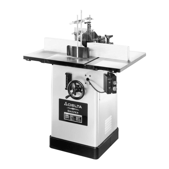
- Page 1 Platinum Edition 2-Speed Heavy-Duty Wood Shaper (Model 43-424) DATED 7-12-00 PART NO. 432-02-651-0018 © Delta Machinery 2000...
-
Page 2: Safety Rules
If you have any questions relative to a particular application, DO NOT use the machine until you have first contacted Delta to determine if it can or should be performed on the product. - Page 3 ADDITIONAL SAFETY RULES FOR WOOD SHAPERS 1. WARNING: DO NOT OPERATE YOUR WOOD SHAPER UNTIL IT IS COMPLETELY ASSEMBLED AND INSTALLED ACCORDING TO THE INSTRUCTIONS. 2. IF YOU ARE NOT thoroughly familiar with the operation of Wood Shapers, obtain advice from your supervisor, instructor or other qualified person.
-
Page 4: Unpacking And Cleaning
ADDITIONAL SAFETY RULES FOR WOOD SHAPERS 23. WHEN SHAPING with collars and starting pin, the cutter should be positioned below the collar whenever possible, as shown in Fig. F. Fig. F 24. MAKE all adjustments with the power “OFF”. 25. KEEP guard in place at all times. 26. - Page 5 4. 10" Wide Cast Iron Extension Wings 5. Wrenches (2) 6. 7/16-20 x 1" Hex Cap Screws (6) for mounting extension wings 7. Flat Washers (6) for mounting extension wings 8. Handwheel 9. Key for Handwheel 10. Lock Knob 11. Guard 12.
- Page 6 27. Fence Body 28. Left and Right fence halves 29. Locking Levers (2) for fence halves 30. Flat Washers (2) for locking levers 31. Spring clamp for fence guard 32. Top cover 33. Guard Mounting Bracket 34. Clear Plastic Guard 35.
-
Page 7: Assembling Extension Wings To Shaper Table
ASSEMBLY INSTRUCTIONS WARNING: FOR YOUR OWN SAFETY, DO NOT CONNECT THE SHAPER TO THE POWER SOURCE UNTIL THE SHAPER IS COMPLETELY ASSEMBLED AND YOU HAVE READ AND UNDERSTOOD THE ENTIRE INSTRUCTION MANUAL. ASSEMBLING SPINDLE RAISING AND LOWERING HANDWHEEL 1. Insert key (A) Fig. 5, into slot in spindle raising and lowering shaft (B) as shown. -
Page 8: Assembling Switch Bracket And On/Off Switch
Fig. 9 ASSEMBLING SWITCH BRACKET AND ON/OFF SWITCH 1. The on/off switch (A) Fig. 9, and switch mounting bracket (B) are shipped inside the shaper cabinet. Open the side door of the shaper cabinet, remove switch package and remove packaging material. 2. -
Page 9: Assembling Fence To Shaper Table
ASSEMBLING FENCE TO SHAPER TABLE 1. The fence on this shaper can be mounted parallel to the miter gage slot using two holes (B) Fig. 14, or 90 degrees to the miter slot by using two holes (A). The following illustrates mounting the fence parallel to the miter gage. - Page 10 5. Fig. 19, illustrates fence body (C) fastened to the table with the two fence locking handles (F). 6. Loosen locking lever (D) Fig. 20, and slide rear of fence half (G) onto locking bar (E). Assemble remaining fence half in the same manner. Then tighten locking lever (D) to secure each fence half to the fence body.
- Page 11 TO FENCE BODY 1. Assemble guard bracket (A) Fig. 24, and hex rod (B) to upright hex shaft (C) as shown. 2. Assemble two guard brackets (A) Fig. 25, and clear plastic guard (D) to holddown (E) as shown. 3. Assemble holddown/clear plastic guard assembly to hex rod (B) as shown in Fig.
-
Page 12: Assembling And Changing Spindles
mounted in the alternate position, 90 degrees to miter gage slot. ASSEMBLING AND CHANGING SPINDLES MAKE CERTAIN THE MACHINE IS DISCONNECTED FROM THE POWER SOURCE. 1. Thread one end of the tie rod (A) Fig. 30, into the threaded hole in the bottom of the spindle (B). 2. -
Page 13: Assembling Table Inserts
ASSEMBLING TABLE INSERTS Three table inserts are provided for various size cutters, as shown in Fig. 34. The large insert is adjustable and should be set flush with the table as follows: 1. Remove the three slotted head screws (A) Fig. 34. 2. -
Page 14: Assembling Spindle Guard
A 4-1/2" diameter spindle guard is supplied as standard equipment and is supplied with a 1/2" bushing which enables the guard to be used with both the 1/2" and 3/4" spindles. CAUTION: The diameter of the spindle guard should be at least 1" more than the maximum cutting circle of the shaper cutter and the height of the guard should not exceed 1/4"... -
Page 15: Connecting Shaper To Power Source
CONNECTING SHAPER TO POWER SOURCE GROUNDING INSTRUCTIONS CAUTION: THIS TOOL MUST BE GROUNDED WHILE IN USE TO PROTECT THE OPERATOR FROM ELECTRIC SHOCK. In the event of a malfunction or breakdown, grounding provides a path of least resistance for electric current to reduce the risk of electric shock. -
Page 16: Operating Controls And Adjustments
OPERATING CONTROLS AND ADJUSTMENTS STARTING AND STOPPING THE SHAPER To apply power to the machine, push “ON” button (A) Fig. 43. To stop the machine, push “OFF” button (B). LOCKING SWITCH IN THE “OFF” POSITION IMPORTANT: We suggest that when the shaper is not in use, the switch be locked in the “OFF”... -
Page 17: Raising And Lowering Spindle
LOWERING SPINDLE The spindle can be raised or lowered by loosening lock knob (A) Fig. 45, and turning handwheel (B). To raise the spindle height, turn the handwheel (B) clockwise. To lower the spindle height, turn handle (B) counterclockwise. The scale (C) Fig. 45, indicates the spindle travel range from 0 to 3"... -
Page 18: Fence Controls And Adjustments
FENCE CONTROLS AND ADJUSTMENTS 1. DISCONNECT SHAPER FROM POWER SOURCE. IMPORTANT: The fence halves (A) Fig. 48, should be adjusted endwise so the opening at the spindle is never more than is required to clear the cutter. 2. To adjust the fence halves (A) Fig. 48 endwise, loosen the two fence locking levers (B), slide the fence halves to the required positions, and tighten locking levers (B). -
Page 19: Guard Controls And Adjustments
GUARD CONTROLS AND ADJUSTMENTS DISCONNECT SHAPER FROM POWER SOURCE. The spring clamp (A) Fig. 52, holddown (B), and clear plastic guard (C) are fully adjustable to provide safe protection for most applications. NOTE: For certain applications, the supplied spindle guard may have to be used or a custom guard may need to be fabricated. -
Page 20: Shaping When Using The Fence As A Guide
4. Loosen thumb screws on guard mounting bracket (P) Fig. 56, and adjust spring clamp (N) so it will provide inward pressure on workpiece; then tighten thumb screws. NOTE: Thumb screws on guard mounting bracket (R) Fig. 56, can be loosened to permit extension of guard assembly. -
Page 21: Shaping With Collars And Starting Pin
When shaping with collars and starting pin, the following rules must always be followed for good work and safety in operation. 1. Collars MUST be smooth and free of all gum or other substances. 2. The edge of the work to be shaped MUST be smooth, as any irregularity in the surface which rides against the collar will be duplicated on the moulded surface. -
Page 22: Replacing Spindle Cartridge
Fig. 67 STARTING PIN 1. Your machine is supplied with a tapered starting pin (A) Fig. 67, which is used as a support when starting the cut. The starting pin (A) is placed on one of the tapered holes (B) in the table. 2. - Page 23 Delta Shaper Accessories High-Speed Steel 3-Lip Shaper Cutters All have " spindle hole. Involute relief design permits honing of the face without changing the shape. Cutters 09-128 & 09-137 are counterbored to fit Stub Spindle. Cutters are shown 3/8 size.
- Page 24 Delta Shaper Accessories Door Edge Detail All 2 " diameter. " bore, " T-Bushing. Flute or Half Round Convex All 2 " diameter. " bore, " T-Bushing. Width Cat. No. Width Cat. No. " 42-070 " 42-072 " 42-071 "...
- Page 25 Delta Shaper Accessories Male and Female Sash All 2 " diameter. " bore with " T-Bushing. Horizontal Panel Raising For cutting " material. With 15° shear for optimum cutting both with and across the grain. Use 42-120 Rub Bearing with 4 "...
- Page 26 Delta Shaper Accessories Double Sided 8-Cutter Cope and Pattern Set Includes " and " wide x " tongue and groove cutters. All 2 " diameter unless otherwise noted. " bore. For use with 42-122 rub bearing. For cutting 1 "...
-
Page 27: Parts, Service Or Warranty Assistance
Delta Building Trades and Home Shop Machinery Two Year Limited Warranty Delta will repair or replace, at its expense and at its option, any Delta machine, machine part, or machine accessory which in normal use has proven to be defective in workmanship or material,...
Need help?
Do you have a question about the 43-424 and is the answer not in the manual?
Questions and answers