Cisco Firepower 9300 Manual
- Hardware installation manual (84 pages) ,
- Installation & maintenance (36 pages) ,
- Command reference manual (421 pages)
Advertisement
- 1 Features
- 2 Chassis Components
- 3 Deployment Options
- 4 Package Contents
- 5 Serial Number Location
- 6 Front Panel
- 7 Rear Panel
- 8 Supervisor
- 9 Security Modules
- 10 Network Modules
- 11 Hardware Bypass Network Modules
- 12 Power Supply Modules
- 13 Fan Modules
- 14 Supported SFP/SFP+ and QSFP Transceivers
- 15 Hardware Specifications
- 16 Product ID Numbers
- 17 Power Cord Specifications
- 18 Documents / Resources
Features
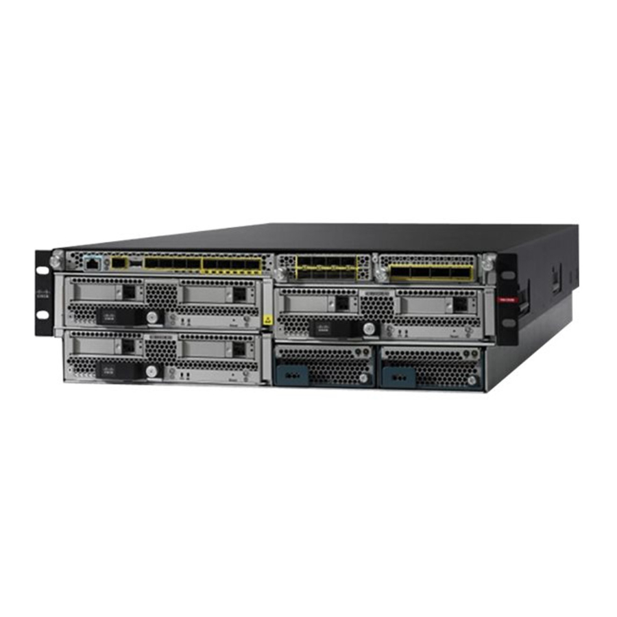
The Cisco Firepower 9300 security appliance is a next generation network and content security platform. Its modular standalone chassis offers high-performance and flexible I/O options, which enable it to run multiple security services simultaneously.
The Firepower 9300 runs FXOS and can deploy multiple application types. See Cisco Firepower 4100/9300 FXOS Compatibility for more information about software version support for each component in the Firepower 9300. See Product ID Numbers for a list of the component product IDs (PIDs) associated with the Firepower 9300.
The following figure shows a fully populated Firepower 9300.
Figure1: Firepower9300

The following table lists the hardware features of the Firepower 9300.
Table 1: Firepower 9300 Features
| Feature | Description |
| Security standards certifications |
|
| Network Equipment Building Systems (NEBS) certification | NEBS certification for the following security modules:
|
| Form factor | 3 RU |
| Rack mount | Mount rails included (4-post EIA-310-D rack) with span between front and rear rails of 24 to 36 in. |
| Airflow | Front to rear Cold aisle to hot aisle |
| Supervisor | Cisco Firepower 9300 Supervisor with eight 10-Gigabit Ethernet ports and two network module slots for I/O expansion See Chassis Components for more information about the chassis Supervisor. |
| Security module slots | Three |
| Supported security modules |
Note SM-24, SM-36, and SM-44 are not supported in Secure Firewall Threat Defense 7.3 and later or Secure Firewall ASA 9.19 and later. |
| Network module slots | Two Located in the Supervisor |
| Supported network modules |
You can deploy the Firepower 9300 as a dedicated threat sensor with hardware bypass network modules. |
| Memory | 256-GB DDR4 DRAM per security module |
| Maximum number of interfaces | Up to twenty-four 10-Gigabit Ethernet (SFP+) interfaces; up to eight 40-Gigabit Ethernet (QSFP+) interfaces with two network modules; up to eight 100-Gigabit Ethernet (SFP+) interfaces |
| Management port | One Gigabit Ethernet port on the Supervisor Supports 1-Gb fiber and copper SFPs |
| Serial port | One RJ-45 console |
| USB port | One USB 2.0 Type A |
| Pullout asset card | Displays serial number |
| Grounding lug | On rear panel |
| Locator beacon | On front panel |
| Power switch | On rear panel Note The initial Firepower 9300 chassis does not have a power switch. |
| Power supply slots | Two On rear panel |
| Power supply types | AC, DC, and HVDC Note Do not mix power supply types or wattage. |
| Redundant power | Yes 1 + 1 |
| Fan slots | Four (hot-swappable) On rear panel |
| Storage | SM-24, SM-36, SM-44—Up to 2.4 TB per chassis (1.2 TB per security module in RAID 1 configuration) SM-40, SM-48, SM-56—UP to 4.8 TB per chassis (1.6 TB per security module in RAID 1 Configuration) |
Chassis Components
The Firepower 9300 chassis contains the following components:
- Firepower 9300 Supervisor—Chassis supervisor module
- Management port
- RJ-45 console port
- USB Type A port
- Eight ports for 1- or 10-Gigabit Ethernet small form-factor pluggable (SFP) ports (fiber and copper)
- Firepower 9300 Security Module—Up to three security modules
- Firepower Network Module—Two single-wide network modules or one double-wide network module
- Two power supply modules (AC or DC)
- Four fan modules
Power Switch
 Note
Note
The initial Firepower 9300 AC chassis has no external power switch. You reset the Firepower 9300 using CLI commands. To physically power cycle the 9300, you must unplug the power cord and then plug the power cord back in.
Note
After removing power from the chassis either by moving the power switch to OFF or unplugging the power cord, wait at least 10 seconds before turning power back ON.
The Firepower 9300 chassis has a standby power switch at the rear of the chassis. It controls both power supply modules. You must shut down the software applications gracefully before turning the switch to OFF.

Turning the switch to OFF turns off the main power to the Supervisor and the security modules regardless of the software status, which can result in the loss of any data in transit and the corruption of data on the SSDs. You must shut down the software applications gracefully before turning the switch to OFF.
Graceful Shutdown of the Chassis
You can gracefully shut down the chassis from either the CLI or Chassis Manager.
See the "Powering Off the Firepower 4100/9300 Chassis" topic in the System Administration chapter in the FXOS CLI Configuration Guide for your software version for the procedure to shut down the chassis from the CLI. The graceful shutdown usually takes as little as a few seconds to as long as three minutes. When the System Halted message appears, you can move the power switch on the rear of the chassis to OFF.
See "Powering Off the Firepower 4100/9300 Chassis" topic in the System Administration chapter in the FXOS Configuration Guide for your software version for the procedure to shut down the chassis from the Chassis Manager. After the shutdown is completed, you can move the power switch on the rear of the chassis to OFF.
When you shut down the chassis, the security modules are automatically shut down.
Graceful Shutdown of the Security Modules
You can shut down the security modules individually from the CLI, the Chassis Manager, or you can use the power switch on the front of each security module. Push the power button briefly on the front panel of each security module. When the power button changes to amber, you can move the power switch on the rear of the chassis to OFF.
Shut the security modules down individually when you are replacing a security module.
Note
You must push the power button on each security module installed in the 9300 chassis. You can have up to three security modules installed in the chassis.
See the "Power Off/On an Installed Module/Engine" in the Security/Module/Engine Management chapter of the FXOS CLI Configuration Guide for your software version for the procedure to shut down the security modules gracefully using CLI commands from the Supervisor. When you see Oper Power: off for all slots, you can move the power switch on the rear of the chassis to OFF.
See the "Power Off/On an Installed Security Module/Engine" topic in the Security Module/Engine Management chapter of the FXOS Configuration Guide for your software version for the procedure to shut down the security module from the Chassis Manager. After the shutdown is complete, you can move the power switch on the rear of the chassis to OFF.
Deployment Options
Here are some examples of how you can deploy the Firepower 9300:
- At the core/aggregation layer of a three-tier data center in a high availability configuration.
- As a dedicated multifunction security service within converged infrastructure stacks (vBlock, FlexPod, for example) at the access layer.
- As a high-performance data center security appliance between the WAN edge and data center core in an high availability configuration.
- As a leaf that exclusively offers security functions in a spine/leaf data center design.
Package Contents
The following figure shows the package contents for the Firepower 9300. Note that the contents are subject to change and your exact contents might contain additional or fewer items.
Figure 2: Firepower 9300 Package Contents

- Firepower 9300 chassis
- Blue console cable PC terminal adapter
- Two power cords (country specific)
- Two rack static rails
Adjusts to fit racks with a 24 in. to 36 in. front-to-rear rail span - Four 10-32 x.5 inch screws used to attach the rails to rack
- Four 10-32 retention nuts for rack-mounting
- Four 10-32 x.75 inch Philips head screws used to attach the chassis to the rack
- 10/100/1000BASE-T SFP transceiver
- One ground lug #6 AWG, 90 degree, #10 post
Note
The ground lug ships with the DC power version of the Firepower 9300. - Two 10-32 x.375 inch screws used to attach the ground lug
- Cisco Firepower 9300
This document has links to the hardware installation guide, regulatory and safety information guide, and warranty and licensing information. It also contains a QR code and URL that point to the Digital Documentation Portal. The portal contains links to the product information page, the hardware installation guide, the regulatory and safety information guide, and the getting started guide.
Serial Number Location
The serial number for the Firepower 9300 chassis is located on the pullout asset card on the front panel, on the side of the chassis, and on the Supervisor.
Figure 3: Serial Numbers on the 9300 Chassis

You can also view additional model information on the compliance label located on the bottom of the chassis.
Front Panel Figure 4:Compliance Label on the 9300 Chassis

For More Information
For the procedure to remove the Supervisor so that you can see the serial number, see Remove and Replace the Supervisor.
Front Panel
The following figure shows the front panel of the Firepower 9300.
Figure 5: Firepower 9300 Front Panel

- Security module 3
- Security module 1
- RJ-45 console port
- 1 Gigabit Ethernet management port
- 2.0 USB port
- Eight 10 Gigabit Ethernet data ports (Gigabit Ethernet 1/1 through 1/8)
- Supervisor
- Network module 1
- Network module 2
- Security module 2
- Power supply module PSU-2
- Power supply module PSU-1
For More Information
- See Chassis Components for a list of all of the chassis components.
- See Supervisor for detailed information about the Supervisor.
- See Security Modules for detailed information about the security modules.
- See Network Modules for detailed information about the network modules.
- See Hardware Bypass Network Modules for detailed information about hardware bypass network modules
- See Power Supply Modules for detailed information about the power supply modules.
Rear Panel
The following figure shows the rear panel of the Firepower 9300.
Figure 6: Firepower 9300 Rear Panel

- Power feed for PSU-2
- Power feed for PSU-1
- On/Off switch
- Fan module FAN-1
- Fan module FAN-2
- Fan module FAN-3
- Fan module FAN-4
- Grounding lug
For More Information
- See Chassis Components for detailed information about the power switch.
- See Fan Modules for detailed information about the fan modules.
- See Power Supply Modules for detailed information about the power supply modules.
Supervisor
The Firepower 9300 contains a supervisor management I/O card called the Firepower 9300 Supervisor, which is located on the front panel. The Supervisor provides chassis management and eight 1- or 10-Gb SFP+ interfaces, and it directs traffic to/from the Firepower 9300 security modules.
Note
Unless you are running FXOS software, if you change the SFP transceiver for the management interface, you must reboot the Firepower 9300. FXOS then detects the new SFP module.
The Supervisor has the following ports:
- RJ-45 console port
- One Gigabit Ethernet SFP management port
- USB 3.0 Type A port
- Eight ports that support 1- or 10-Gigabit Ethernet SFPs (fiber and copper) (Ethernet 1/1 through 1/8)
Figure 7: Firepower 9300 Supervisor Front Panel

- RJ-45 console port
- Gigabit Ethernet management port
- USB Type A port
- SFP/SFP+ ports that support 1-G or 10-G Ethernet (copper or fiber)
- Locator/Beacon (push button) and LED:
- Off—Locate is off.
- Blue—Locate is on.
- Management LED:
- Off—No connection or port is not in use.
- Amber—No link or network failure.
- Green—Link up.
- Green, flashing—Network activity.
- Power LED:
- Off—No power.
- Green—System has power.
- ACT LED This LED is not supported; reserved for future use.
- SYS LED:
- Off—System is not booting up yet.
- Green, flashing—Power-up diagnostics is complete and the system is booting up.
- Green—System has booted up successfully.
- Amber—Power-up diagnostics have failed.
- Amber, flashing—Alarm; power-up diagnostics are running.
- Network port status LEDs:
- Off—No connection or port is not in use.
- Amber—No link or network failure.
- Green—Network activity up to 1 G.
- Green, flashing—Network activity faster than 1 G.
RJ-45 Console Port
The Firepower 9300 has a standard RJ-45 console port. You can use the CLI to configure your Firepower 9300 through the RJ-45 serial console port by using a terminal server or a terminal emulation program on a computer.
The RJ-45 (8P8C) port supports RS-232 signaling to an internal UART controller. The console port does not have any hardware flow control, and does not support a remote dial-in modem. The baud rate is 9600. You can use the standard cable found in your accessory kit to convert the RJ-45 to DB-9 if necessary.
Type A USB Port
You can use the external USB Type A port to attach a data storage device. The external USB drive identifier is disk1:. The USB Type A port supports the following:
- Hot swapping
- USB drive formatted with FAT32
- Boot kick-start image from the Supervisor ROMMON for discovery recovery purposes
- Copy files to and from workspace:/ and volatile:/ within local-mgmt. The most relevant files are:
- Core files
- Ethanalyzer packet captures
- Tech-support files
- Security module log files
- Platform bundle image upload usingdownload image usbA:
The USB Type A port does not support Cisco Secure Package (CSP) image upload.
Network Ports
The Firepower 9300 chassis has eight ports that require SFP/SFP+/QSFP transceivers (fiber or copper). They are numbered from left to right starting with 1 and are named Ethernet 1/1 through Ethernet 1/8. The 9300 also has two network module slots that support different numbers of ports depending on the network module. See Network Modules for the supported network modules. See for Supported SFP/SFP+ and QSFP Transceivers the list of supported transceivers.
Each port has LEDs that represent link/activity status.
Management Port
The Firepower 9300 chassis has a management port on the Supervisor that requires a 1-Gb fiber or copper SFP.
Security Modules
The Firepower 9300 has three slots for security modules. The security modules are hot-swappable.
Note
Make sure you have the correct firmware package and software version installed to support your security module. For instructions on how to verify your firmware package version and to upgrade the firmware if necessary, see the Cisco Firepower 4100/9300 FXOS Firmware Upgrade Guide. See Cisco Firepower 4100/9300 FXOS Compatibility for the software compatibility matrix.
Note
For FXOS software versions before version 2.6.1, all security modules in the chassis must be the same type; you cannot mix security module types. For version 2.6.1 and later, you can mix different types of security modules in the same chassis.
Figure 8: Firepower 9300 Security Module Front Panel

- Paper tab for server name or serial number
- Security module ejector handle
- Ejector handle captive screw
- SSD bay 1
- SSD bay 2
- Power button and LED
- Off—No power.
- Green—System has power.
- Amber—Standby power.
- Network link status LED
- Off—No network connection.
- Green—At least one network is up.
- Green, flashing—Network activity faster than 1 G.
- Security module health LED
- Off—Power off.
- Green—Normal operation.
- Amber—Minor error.
- Amber, flashing—Critical error.
- Reset button
Note
The reset button is not in use. The functionality of the reset switch is disabled on the Firepower 9300. - Locator/Beacon (push button) and LED
- Off—Locate is off.
- Blue—Locate is on.
There are six supported security modules:
Note
SM-24, SM-36, and SM-44 are not supported in threat defense 7.3 and later or ASA 9.19 and later.
- SM-24—24-physical core CPU security module (NEBS ready)
- SM-36—36-physical core CPU high performance security module
- SM-40—40-physical core CPU Crypto security module (NEBS ready)
- SM-44—44-physical core CPU high performance security module (NEBS ready)
- SM-48—48-physical core CPU Crypto security module (NEBS ready)
- SM-56—56-physical core CPU Crypto security module
The SM-24, SM-36, and SM-44 have the following features:
- 256 GB of DDR4 memory.
- Two 800-GB SSDs.
The security module ships with two 800-GB SSDs in a default RAID 1 configuration that provides storage support. There are two LEDs on the front of the SSDs. - One security acceleration module.
The SM-40, SM-48, and SM-56 have the following features:
- 384 GB of DDR4 memory.
- Two 1.6 TB SSDs.
The security module ships with two 1.6 TB SSDs in a default RAID 1 configuration that provides storage support. There are two LEDs on the front of the SSDs. - One enhanced security acceleration module.
Note
All security module components except the SSDs are fixed. You cannot configure or remove any of the other components.

If you replace a security module with a new security module, you must decommission the old security module. See the "Security Module/Engine Management" chapter in the FXOS Configuration Guide for your software version for the instructions. See Remove and Replace the Security Module for the procedure for replacing security modules.
Network Modules
The Firepower 9300 contains two network module slots that provide optical or electrical network interfaces. Network modules are optional, removable I/O modules that provide either additional ports or different interface types (1/10/40/100 Gb).
The Firepower network modules plug into the chassis on the front panel. You can also remove the divider between the two network module slots and insert a double-wide network module.
For More Information
- See 10-Gb Network Module for a description of the 10-Gb network module.
- See 40-Gb Network Module for a description of the 40-Gb network module.
- See 100-Gb Network Module for a description of the 100-Gb two-port single-wide network module.
- See 100-Gb Network Module for a description of the 100-Gb four-port single-wide network module
- See 100-Gb Network Module (Double Wide) for a description of the 100-Gb double-wide network module.
- See Supported SFP/SFP+ and QSFP Transceivers for a list of supported SFPs.
- See Install, Remove, and Replace the Single-Wide Network Module for the procedure for removing and replacing single-wide network modules.
- See Install, Remove, and Replace the Double-Wide Network Module for the procedure for removing and replacing double-wide network modules.
10-Gb Network Module
The following figure shows the front panel of the 10-Gb single-wide network module (FPR9K-NM-8X10G). The eight ports are numbered from top to bottom, left to right.
Note
Make sure you have the correct firmware package and software version installed to support this network module. For instructions on how to verify your firmware package version and to upgrade the firmware if necessary, seetheCiscoFirepower4100/9300FXOSFirmwareUpgradeGuide.SeeCiscoFirepower4100/9300 FXOS Compatibility for the software compatibility matrix.
Note
The FPR9K-NM-8X10G is NEBS-compliant.
Note
You can fit four copper SFPs in either the top row of ports or the bottom row of ports. Both rows cannot be populated at the same time, because of the port row spacing.
Figure 9: FPR9K-NM-8X10G

- Captive screw/handle
- Ethernet X/1
- Ethernet X/3
- Ethernet X/5
- Ethernet X/7
- Ethernet X/2
- Ethernet X/4
- Ethernet X/6
- Ethernet X/8
- Network activity LEDs
- Off—No connection or port is not in use.
- Amber—No link or network failure.
- Green—Link up.
- Green, flashing—Network activity.
For More Information
- For a list of copper SFPs, see Supported SFP/SFP+ and QSFP Transceivers.
40-Gb Network Module
The following figure shows the front panel of the 40-Gb network module (FPR9K-NM-4X40G.) The FPR9K-NM-4X40G is a single-wide module that supports hot swapping. The four ports are numbered left to right.
Note
Make sure you have the correct firmware package and software version installed to support this network module. For instructions on how to verify your firmware package version and to upgrade the firmware if necessary, see the CiscoFirepower4100/9300FXOSFirmwareUpgradeGuide. See CiscoFirepower4100/9300 FXOS Compatibility for the software compatibility matrix.
Note
The FPR9K-NM-4X40G is NEBS-compliant.
Figure 10: FPR9K-NM-4X40G

- Captive screw/handle
- Network activity LEDs
- Off—No connection or port is not in use.
- Amber—No link or network failure.
- Green—Link up.
- Green, flashing—Network activity.
- 40Gb—Only the leftmost LED indicates the port status.
- 4x10Gb—Each of the port LEDS indicates the status of respective 10-Gb channel.
- Ethernet X/1
- Ethernet X/2
- Ethernet X/3
- Ethernet X/4
100-Gb Network Module
The following figure shows the front panel of the 100-Gb network module (FPR9K-NM-2X100G). The FPR9K-NM-2X100G is a two-port single-widemodule that supports hot swapping. The two ports are numbered left to right.
Note
Make sure you have the correct firmware package and software version installed to support this network module. For instructions on how to verify your firmware package version and to upgrade the firmware if necessary, see the CiscoFirepower4100/9300FXOSFirmwareUpgradeGuide. See CiscoFirepower4100/9300 FXOS Compatibility for the software compatibility matrix.
Figure 11: FPR9K-NM-2X100G

- Power LED
- Network activity LEDs
- Off—No connection or port is not in use.
- Amber—No link or network failure.
- Green—Link up.
- Green, flashing—Network activity.
- Network activity LEDs
- Off—No connection or port is not in use.
- Amber—No link or network failure.
- Green—Link up.
- Green, flashing—Network activity.
- Ethernet X/1
- Ethernet X/2
- Captive screw/handle
100-Gb Network Module
The following figure shows the front panel of the 100-Gb network module (FPR9K-NM-4X100G). The FPR9K-NM-4X100G is a four-port single-wide module that supports hot swapping. The four ports are numbered left to right.
Note
Make sure you have the correct firmware package and software version installed to support this network module. For instructions on how to verify your firmware package version and to upgrade the firmware if necessary, see the CiscoFirepower4100/9300FXOSFirmwareUpgradeGuide. See CiscoFirepower4100/9300 FXOS Compatibility for the software compatibility matrix.
Figure 12: FPR9K-NM-4X100G

- Power LED
- Ethernet X/1
- Ethernet X/2
- Ethernet X/3
- Ethernet X/4
- Captive screw/handle
- Network activity LEDs
- Off—No connection or port is not in use.
- Amber—No link or network failure.
- Green—Link up.
- Green, flashing —Network activity.
100-Gb Network Module (Double Wide)
The following figure shows the front panel of the 100-Gb network module (FPR9K-DNM-2X100G). The FPR9K-DNM-2X100G is a double-wide module that does not support hot swapping. The two ports are numbered left to right.
Hardware Bypass Network Modules
Note
Make sure you have the correct firmware package and software version installed to support this network module. For instructions on how to verify your firmware package version and to upgrade the firmware if necessary, see the CiscoFirepower4100/9300FXOSFirmwareUpgradeGuide. See CiscoFirepower4100/9300 FXOS Compatibility for the software compatibility matrix.
Figure 13: FPRK9-DNM-2X100G

- Captive screw/handle
- 100-Gigabit Ethernet QSFP28 fiber port Ethernet X/1
- 100-Gigabit Ethernet QSFP28 fiber port Ethernet X/2
- Network activity LEDs
- Unlit—No connection or port is not in use.
- Amber—No link or network failure.
- Green, flashing—Network activity.
Hardware Bypass Network Modules
Hardware bypass (also known as fail-to-wire) is a physical layer (Layer 1) bypass that allows paired interfaces to go into bypass mode so that the hardware forwards packets between these port pairs without software intervention. Hardware bypass provides network connectivity when there are software or hardware failures. Hardware bypass is useful on ports where the Firepower security appliance is only monitoring or logging traffic. The hardware bypass network modules have an optical switch that is capable of connecting the two ports when needed. The hardware bypass network modules have built-in SFPs.
Hardware bypass is supported only on a fixed set of ports. You can pair Port 1 with Port 2, Port 3 with Port 4, but you cannot pair Port 1 with Port 4 for example.
Note
When the appliance switches from normal operation to hardware bypass or from hardware bypass back to normal operation, traffic may be interrupted for several seconds. A number of factors can affect the length of the interruption; for example, behavior of the optical link partner such as how it handles link faults and debounce timing; spanning tree protocol convergence; dynamic routing protocol convergence; and so on. During this time, you may experience dropped connections.
There are three configuration options for hardware bypass network modules:
- Passive interfaces—Connection to a single port.
For each network segment you want to monitor passively, connect the cables to one interface. This is how the nonhardware bypass network modules operate. - Inline interfaces—Connection to any two like ports (10 Gb to 10 Gb for example) on one network module, across network modules, or fixed ports.
For each network segment you want to monitor inline, connect the cables to pairs of interfaces. - Inline with hardware bypass interfaces—Connection of a hardware bypass paired set.
For each network segment that you want to configure inline with fail-open, connect the cables to the paired interface set.
For the 40-Gb network module, you connect the two ports to form a paired set. For the 1/10-Gb network modules, you connect the top port to the bottom port to form a hardware bypass paired set. This allows traffic to flow even if the security appliance fails or loses power.
Note
If you have an inline interface set with a mix of hardware bypass and nonhardware bypass interfaces, you cannot enable hardware bypass on this inline interface set. You can only enable hardware bypass on an inline interface set if all the pairs in the inline set are valid hardware bypass pairs.
For More Information
- See 40-Gb Network Module with Hardware Bypass for a description of the 40-Gb network module.
- See 10-Gb SR/10-Gb LR Network Module with Hardware Bypass for a description of the 1-Gb SX, 10-Gb SR and LR network modules.
- See Install, Remove, and Replace the Single-Wide Network Module for the procedure for removing and replacing single-wide network modules.
40-Gb Network Module with Hardware Bypass
The following figure shows the front panel of the 40-Gb hardware bypass network module (FPR9K-NM-2X40G-F). The FPR9K-NM-2X40G-F is a single-wide module that does not support hot swapping. The two ports are numbered left to right. Pair the two ports to create a hardware bypass paired set.
Note
Make sure you have the correct firmware package and software version installed to support this network module. For instructions on how to verify your firmware package version and to upgrade the firmware if necessary, see the CiscoFirepower4100/9300FXOSFirmwareUpgradeGuide. See CiscoFirepower4100/9300 FXOS Compatibility for the software compatibility matrix.
Figure 14: FPR9K-NM-2X40G-F

- Captive screw/handle
- Port 1 Ethernet X/1 Ports 1 and 2 are paired together to form a hardware bypass pair.
- Port 2 Ethernet X/2 Ports 1 and 2 are paired together to form a hardware bypass pair.
- Port 1 network activity LEDs:
- Amber—No connection, or port is not in use, or no link or network failure.
- Green—Link up, no network activity.
- Green, flashing—Network activity.
- BP (bypass LED):
- Green—In standby mode.
- Amber, flashing—Port is in hardware bypass mode, failure event.
- Port 2 network activity LEDs:
- Amber—No connection, or port is not in use, or no link or network failure.
- Green—Link up, no network activity.
- Green, flashing—Network activity.
The following table describes the cable specifications needed to keep the insertion loss as low as possible.
Table 2: 40-Gb BASE-SR Cable Specifications
| Interface | Supported Cable |
| Ethernet 40-G BASE-SR4 | 50 microns core diameter |
| 850 nm wavelength | 2000/4700 (OM3/4) modal bandwidth (MHz*km) |
| MPO-12 port adapter | 50 m cable distance |
Note
See the Cisco 40GBASE QSFP Modules Data Sheet for specifications of the QSFP for the 40-Gb BASE-SR-4.
We recommend the following Cisco OM3 MTP/MPO cables.
Table 3: Cisco Cables
| Cisco Part Number | Cable Length |
| CAB-ETH-40G-5M | 5 m |
| CAB-ETH-40G-10M | 10 m |
| CAB-ETH-40G-20M | 20 m |
10-Gb SR/10-Gb LR Network Module with Hardware Bypass
The following figure shows the front panel of the 10-Gb SR and 10-Gb LR hardware bypass network modules FPR9K-NM-6X10SR-F, FPR9K-NM-6X10LR-F). This is a single-wide module that does not support hot swapping. The six ports are numbered from top to bottom, left to right. Pair ports 1 and 2, 3 and 4, and 5 and 6 to form hardware bypass paired sets.
Note
Make sure you have the correct firmware package and software version installed to support this network module. For instructions on how to verify your firmware package version and to upgrade the firmware if necessary, see the CiscoFirepower4100/9300FXOSFirmwareUpgradeGuide. See CiscoFirepower4100/9300 FXOS Compatibility for the software compatibility matrix.
Figure 15: FPR9K-NM-6X10SR-F, FPR9K-NM-6X10LR-F

- Captive screw/handle
- Six network activity LEDs:
- Amber—No connection, or port is not in use, or no link or network failure.
- Green—Link up, no network activity.
- Green, flashing—Network activity.
- Ethernet X/1 (top port) Ethernet X/2 (bottom port) Ports 1 and 2 are paired together to form a hardware bypass pair.
- Ethernet X/3 (top port) Ethernet X/4 (bottom port) Ports 3 and 4 are paired together to form a hardware bypass pair.
- Ethernet X/5 (top port) Ethernet X/6 (bottom port) Ports 5 and 6 are paired together to form a hardware bypass pair.
- Bypass LEDs B1 through B3:
- Green—In standby mode.
- Amber, flashing—Port is in hardware bypass mode, failure event.
The 10-Gb SR/10-Gb LR network modules have the following insertion loss measurements. Insertion loss measurements help you to troubleshoot the network by verifying cable installation and performance.
Table 4: 10-Gb SR Network Module (FPR9K-NM-6X10SR-F)
| Operating Mode | Typical | Maximum | |
| Insertion loss | Normal | 0.9 dB | 1.4 dB |
| Hardware bypass | 1.2 dB | 1.7 dB | |
| Core diameter (microns) | Modal bandwidth (MHz/km) | Cable distance Note Half the distance specified by the IEEE standard. | |
| Cable and operating distance | 62.5 | 160 (FDDI) | 13 m |
| 62.5 | 200 (OM1) | 16.5 m | |
| 50 | 400 | 33 m | |
| 50 | 500 (OM2) | 41 m | |
| 50 | 2000 (OM3) | 150 m | |
| 50 | 4700 (OM4) | 200 m |
Table 5: 10-Gb LR Network Module (FPR9K-NM-6X10LR-F)
| Operating Mode | Typical | Maximum | |
| Insertion loss | Normal | 1.2 dB | 1.6 dB |
| Hardware bypass | 1.5 dB | 1.9 dB | |
| Cable and operating distance | Core diameter (microns) | Modal bandwidth (MHz/km) | Cable distance Note Half the distance specified by the IEEE standard. |
| G.652 | Single mode | 5 km |
Power Supply Modules
The Firepower 9300 supports two AC, two DC, or two high-voltage DC (HVDC) power supply modules so that dual power supply redundancy protection is available. Facing the front of the chassis, the power supply modules are numbered left to right, for example, PSU-1 and PSU-2.
 Attention
Make sure that one power supply module is always active.
AC Power Supply Modules
The 220-V power supply modules run at 2500 W for 200 to 240 V AC. The load is shared when both power supply modules are plugged in and running at the same time. The power supply modules support hot swapping. The power supply entry module is not removable. This is the module that you plug the power cords into.
Note
After removing power from the chassis either by moving the power switch to OFF or unplugging the power cord, wait at least 10 seconds before turning power back ON.
Table 6: AC Power Supply LEDs
| Power Switch Position | Green LED | Amber LED | |
| No input AC power | On | Off | Off |
| Off | Off | Off | |
| Power supply failure | On | Off | On |
| Off | Off | Flashing Power supply warning, must be reset by the system | |
| Power present | On | On Normal operation | Off |
| Off | Flashing (1 Hz) 12-V output disabled | Off |
DC Power Supply Module
The power switch controls the DC power output. The system input power is +12 V. If the power switch is off (standby) when input DC (-48 V) is present, the main power is turned off and only +3.3 V standby is available for the system. If the power switch position is on (active) when input DC (-48 V) is present, the main power is turned on as well as +3.3 V standby, and the system is running.
Note
After removing power from the chassis either by moving the power switch to OFF or unplugging the power cord, wait at least 10 seconds before turning power back ON.
The following table describes the DC power supply LEDs.
Table 7: DC Power Supply Module LEDs
| Input DC Power -48V | Power Switch Position | Green LED | Amber LED |
| No input DC power | On | Off | Off |
| Off | Off | Off | |
| Power supply failure | On | Off | On |
| Off | Off | Off | |
| Input DC present | On | On | Off |
| Off | Flashing (1 Hz) | Off |
HVDC Power Supply Module
The HVDC power supply modules run at 2500 W for +240 to +380 V DC. The load is shared when both power supply modules are plugged in and running at the same time. The power supply modules are hot-swappable. The power supply entry module is not removable. This is the module that you plug the power cords into.
For More Information
- See Remove and Replace the Power Supply Module for the procedure for removing and replacing the power supply module.
- See Connect the DC Power Supply Module for the procedure for connecting the DC power supply module.
- See Connect the HVDC Power Supply Module for the procedure for connecting the HVDC power supply module.
- See Hardware Specifications for the power supply hardware specifications.
Fan Modules
The Firepower 9300 requires four fan modules, which are hot-swappable. They are installed in the rear of the chassis. When you remove a fan module, make sure you replace it quickly to avoid overheating the system.
The fan modules are numbered left to right, for example, FAN-1, FAN-2, FAN-3, and FAN-4.
The fan modules have the following LEDs:
- Amber, flashing—Fan failure.
- Green—Fan running normally.
For More Information
See Remove and Replace the Fan Module for the procedure for removing and replacing fan modules.
Supported SFP/SFP+ and QSFP Transceivers
The SFP/SFP+ and QSFP transceivers are bidirectional devices with a transmitter and receiver in the same physical package. They are a hot-swappable optical or electrical (copper) interface that plugs into the SFP/SFP+/QSFP ports on the fixed ports and the network module ports, and provides Ethernet connectivity.
Use appropriate ESD procedures when inserting the transceiver. Avoid touching the contacts at the rear, and keep the contacts and ports free of dust and dirt. Keep unused transceivers in the ESD packing that they were shipped in. The following figure shows a sample SFP transceiver.
Figure 16: SFP

- Dust plug
- Bail clasp
- Receive optical bore
- Transmit optical bore
Safety Warnings
Take note of the following optical connection warnings:
Statement 1051—Laser Radiation
Invisible laser radiation may be emitted from disconnected fibers or connectors. Do not stare into beams or view directly with optical instruments.
Statement 1055—Class 1/1M Laser
Invisible laser radiation is present. Do not expose to users of telescopic optics. This applies to Class 1/1M laser products.

Although non-Cisco SFPs are allowed, we do not recommend using them because they have not been tested and validated by Cisco. Cisco TAC may refuse support for any interoperability problems that result from using an untested third-party SFP transceiver.
The following table lists the Cisco supported transceivers.
Table 8: Supported Cisco SFP/SFP+ and QSFP Transceivers
| Optics Type | PID |
| 1 Gb | |
| 1G-SX | GLC-SX-MMD |
| 1G-LH/LX | GLC-LH-SMD |
| 1G-EX | GLC-EX-SMD |
| 1G-ZX | GLC-ZX-SMD |
| 1G 1000Base-T | GLC-T |
| 1G 1000Base-T | GLC-TE |
| 10 Gb | |
| 10G-SR | SFP-10G-SR |
| 10G-SR-S | SFP-10G-SR-S |
| 10G-LR | SFP-10G-LR |
| 10G-LR-S | SFP-10G-LR-S |
| 10G-LRM | SFP-10G-LRM |
| 10G-ER | SFP-10G-ER |
| 10G-ER-S | SFP-10G-ER-S |
| 10G-ZR-S | SFP-10G-ZR-S |
| 10G Cu, 1m | SFP-H10GB-CU1M |
| 10G Cu, 1.5m | SFP-H10GB-CU1-5M |
| 10G Cu, 2m | SFP-H10GB-CU2M |
| 10G Cu, 2.5m | SFP-H10GB-CU2-5M |
| 10G Cu, 3m | SFP-H10GB-CU3M |
| 10G Cu, 5m | SFP-H10GB-CU5M |
| 10G Cu, 7m | SFP-H10GB-ACU7M |
| 10G Cu, 10m | SFP-H10GB-ACU10M |
| 10G AOC, 1m | SFP-10G-AOC1M |
| 10G AOC, 2m | SFP-10G-AOC2M |
| 10G AOC, 3m | SFP-10G-AOC3M |
| 10G AOC, 5m | SFP-10G-AOC5M |
| 10G AOC, 7m | SFP-10G-AOC7M |
| 10G AOC, 10m | SFP-10GAOC10M |
| 40 Gb | |
| 40G-SR4 | QSFP-40G-SR4 |
| 40G-SR4-S | QSFP-40G-SR4-S |
| 40G-CSR4 | QSFP-40G-CSR4 |
| 40G-SRBD | QSFP-40G-SRBD |
| 40GE-LR4 | QSFP-40GE-LR4 |
| 40GE-LR4-S | QSFP-40GE-LR4-S |
| 40G-LR4L | WSP-Q40GLR4L |
| 40G-CU, 1M, 3M, 5M | Cisco QSFP-H40G-CU |
| 40G-4X10G-CU, 1M, 3M, 5M | QSFP-4SFP10G-CU |
| 40G-CU-A, 7M, 10M | Cisco QSFP-H40G-ACU |
| 40G-4X10G-CU-A, 7M, 10M | QSFP-4X10G-AC |
| 40G-AOC, 1M, 2M, 3M, 5M, 7M, 10M, 15M | QSFP-H40G-AOC |
| 100 Gb | |
| 100G-SRBD | QSFP-100G-SRBD |
| 100G-SR1.2 | QSFP-100G-SR1.2 |
| 100G-SR4-S | QSFP-100G-SR4-S |
| 100G-LR4-S | QSFP-100G-LR4-S |
| 100G-AOC, 1m, 2m, 3m, 5m, 7m, 10m, 15m, 20m, 25m, 30m | QSFP-100G-AOCxM |
| 100G-CUxM, 1m, 2m, 3m, 5m | QSFP-100G-CUxM Note Supported only on the 2- and 4-port 100-Gb single-wide network modules (FPR-NM-2X100G and FPR-NM-4X100G). |
Hardware Specifications
The following table contains hardware specifications for the Firepower 9300.
| Physical Specifications for the 9300 Chassis | |
| Dimensions (H x W x D) | 5.25 x 17.5 x 32 inches (13.3 x 44.5 x 81.3 cm) |
| Weight | 105 lb (47.7 kg) with one security module 135 lb (61.2 kg) fully configured |
| Physical Specification for the 9300 Security Module | |
| Dimensions | 1.95 x 8 x 24.2 inches (50 x 203 x 620 mm) |
| Weight | 15.5 lb (7.03 kg) |
| Memory Per 9300 Security Module | |
| DDR4 DIMM | 256 GB—SM-24, SM-36, SM-44 Note The SM-24, SM-36, and SM-44 are not supported on Version 7.3 and later. 384 GB—SM-40, SM-48, SM-56 |
| Power | |
| Input voltage | AC: 200 to 240 V AC DC: -40 to -60 V DC HVDV: 240 to 380 V DC |
| Maximum output power | AC: 2500 W DC: 2500 W HVDC: 2500 W |
| Maximum input current | AC: 15.5 A to 12.9 A DC: 69 A to 42 A HVDC: <14 A at 200 V |
| Redundancy | 1+1 |
| Frequency | 50 to 60 Hz |
| Efficiency | 92% (at 50% load) |
| Environment | |
| Operating temperature | SM-24 security module: 32 to 104°F (0 to 40°C) SM-36, SM-44, SM-40, SM-48 SM-56 security modules: 32 to 88°F (0 to 35°C) at sea-level |
| Nonoperating temperature | -40 to 149°F (-40 to 65°C); maximum altitude is 40,000 ft |
| Temperature NEBS | Long Term: 0 to 45°C up to 6000 ft (1829 m) Long Term: 0 to 35°C, 6000-13000 ft (1829-3964 m) Short Term: -5 to 55°C, up to 6000 ft (1829 m) Note Firepower 9300 NEBS compliance applies only to the SM-24 and SM-44 security module configurations. |
| Humidity | 5 to 95% noncondensing (operating and nonoperating) |
| Operating altitude | SM-24 security module: 0 to 13,000 ft (3962 m) SM-36, SM-44, SM-40, SM-48, SM-56 security modules: 0 to 10,000 ft (3048 m.) |
| Nonoperating altitude | 40,000 ft (12,192 m) |
| Acoustic noise | 75.5 dBa at maximum fan speed |
Product ID Numbers
The following table lists the PIDs associated with the Firepower 9300. All of the PIDs in the table are field-replaceable. If you need to get a return material authorization (RMA) for any component, see Cisco Returns Portal for more information.
Note
See the show inventory command in the Cisco Firepower 4100/9300 FXOS Command Reference, in the Cisco Firepower Threat Defense Command Reference, or in the Cisco ASA Series Command Reference to display a list of the PIDs for your Firepower 9300.
Table 9: Firepower 9300 PIDs
| PID | Description |
| FPR-C9300= | Firepower 9300 chassis, no power supply modules and no fan modules (spare) |
| FPR-C9300-AC | Firepower 9300 chassis for AC power |
| FPR-C9300-AC= | Firepower 9300 chassis for AC power, no power supply modules and no fan modules (spare) |
| FPR-C9300-DC | Firepower 9300 chassis for DC power, two power supply modules and four fan modules |
| FPR-C9300-DC= | Firepower 9300 chassis for DC power, two power supply modules and four fan modules (spare) |
| FPR-C9300-HVDC | Firepower 9300 chassis for HVDC power supply, two power supply modules and four fan modules |
| FPR-C9300-HVDC= | Firepower 9300 chassis for HVDC power, no power supply modules and no fan modules (spare) |
| FPR-C9300-FIPSKIT= | Firepower 9300 chassis FIPS kit (spare) |
| FPR9K-SUP | Firepower 9000 series Supervisor |
| FPR9K-SUP= | Firepower 9000 series Supervisor (spare) |
| FPR9K-SM-24 | Firepower 9000 series security module |
| FPR9K-SM-24= | Firepower 9000 series security module (spare) |
| FPR9K-SM-24-NEB | Firepower 9000 series NEBS security module |
| FPR9K-SM-24-NEB= | Firepower 9000 series NEBS security module (spare) |
| FPR9K-SM-36 | Firepower 9000 series high performance security module |
| FPR9K-SM-36= | Firepower 9000 series high performance security module (spare) |
| FPR9K-SM-40 | Firepower 9000 series Crypto security module |
| FPR9K-SM-40= | Firepower 9000 series Crypto security module (spare) |
| FPR9K-SM-40-NEB | Firepower 9000 series NEBS Crypto security module |
| FPR9K-SM-40-NEB= | Firepower 9000 series NEBS Crypto security module (spare) |
| FPR9K-SM-44 | Firepower 9000 series high performance security module |
| FPR9K-SM-44= | Firepower 9000 series high performance security module (spare) |
| FPR9K-SM-44-NEB | Firepower 9000 series NEBS security module |
| FPR9K-SM-44-NEB= | Firepower 9000 series NEBS security module (spare) |
| FPR9K-SM-48 | Firepower 9000 series Crypto security module |
| FPR9K-SM-48= | Firepower 9000 series Crypto security module (spare) |
| FPR9K-SM-48-NEB | Firepower 9000 series NEBS Crypto security module |
| FPR9K-SM-48-NEB= | Firepower 9000 series NEBS Crypto security module (spare) |
| FPR9K-SM-56 | Firepower 9000 series Crypto security module |
| FPR9K-SM-56= | Firepower 9000 series Crypto security module (spare) |
| FPR9K-SM-BLANK | Firepower 9000 series security module blank slot cover |
| FPR9K-SM-BLANK= | Firepower 9000 series security module blank slot cover (spare) |
| FPR9K-DNM-2X100G | Firepower 2-port 100-Gb double-wide network module |
| FPR9K-DNM-2X100G= | Firepower 2-port 100-Gb double-wide network module (spare) |
| FPR9K-DNM2X100G-RF | Firepower 2-port 100-Gb double-wide network module, REMANUFACTURED |
| FPR9K-NM-2X100G | Firepower 2-port 100-Gb single-wide network module |
| FPR9K-NM-2X100G= | Firepower 2-port 100-Gb single-wide network module (spare) |
| FPR9K-NM-4X100G | Firepower 4-port 100-Gb single-wide network module |
| FPR9K-NM-4X100G= | Firepower 4-port 100-Gb single-wide network module (spare) |
| FPR9K-NM-2X40G-F | Firepower 2-port 40-Gb SR hardware bypass network module |
| FPR9K-NM-2X40G-F= | Firepower 2-port 40-Gb SR hardware bypass network module (spare) |
| FPR9K-NM-4X40G | Firepower 9000 series 4-port 40-Gb QSFP+ network module |
| FPR9K-NM-4X40G= | Firepower 9000 series 4-port 40-Gb QSFP+ network module (spare) |
| FPR9K-NM-6X10LR-F | Firepower 6-port 10-Gb LR hardware bypass network module |
| FPR9K-NM-6X10LR-F= | Firepower 6-port 10-Gb LR hardware bypass network module (spare) |
| FPR9K-NM-6X10SR-F | Firepower 6-port 10-Gb SR hardware bypass network module |
| FPR9K-NM-6X10SR-F= | Firepower 6-port 10-Gb SR hardware bypass network module (spare) |
| FPR9K-NM-8X10G | Firepower 9000 series 8-port 10-Gb SFP+ network module |
| FPR9K-NM-8X10G= | Firepower 9000 series 8-port 10-Gb SFP+ network module (spare) |
| FPR9K-NM-BLANK | Firepower 9000 series network module blank slot cover |
| FPR9K-NM-BLANK= | Firepower 9000 series network module blank slot cover (spare) |
| FPR9K-NM-DV | Firepower 9000 series network module divider |
| FPR9K-PS-AC | Firepower 9000 series AC power supply module |
| FPR9K-PS-AC= | Firepower 9000 series AC power supply module (spare) |
| FPR9K-PS-DC | Firepower 9000 series DC power supply module |
| FPR9K-PS-DC= | Firepower 9000 series DC power supply module (spare) |
| FPR9K-PS-HVDC | Firepower 9000 series HVDC power supply module |
| FPR9K-PS-HVDC= | Firepower 9000 series HVDC power supply module (spare) |
| FPR9K-FAN | Firepower 9000 series fan module |
| FPR9K-FAN= | Firepower 9000 series fan module (spare) |
| FPR9K-SM-S800GS1 | Firepower 9000 series 800-GB SSD for the SM-24, SM-36, and SM-44 security modules |
| FPR9K-SM-S800GS1= | Firepower 9000 series 800-GB SSD for the SM-24, SM-36, and SM-44 security modules (spare) |
| FPR9K-SM-SSD1.6TB | Firepower 9000 series 1.6-TB SSD for the SM-40, SM-48, and SM-56 security modules |
| FPR9K-SM-SSD1.6TB= | Firepower 9000 series 1.6-TB SSD for the SM-40, SM-48, and SM-56 security modules (spare) |
| FPR9K-RMK | Firepower 9000 series rack-mount kit |
| FPR9K-RMK= | Firepower 9000 series rack-mount kit (spare) |
Power Cord Specifications
Each power supply has a separate power cord. Standard power cords or jumper power cords are available for connection to the security appliance. The jumper power cords for use in racks are available as an optional alternative to the standard power cords. The chassis ships with one power cord; the default is the US version. You must choose the country-specific power cord when ordering your security appliance.
If you do not order the optional power cord with the system, you are responsible for selecting the appropriate power cord for the product. Using an incompatible power cord with this product may result in electrical safety hazard. Orders delivered to Argentina, Brazil, and Japan must have the appropriate power cord ordered with the system.
Note
Only the approved power cords or jumper power cords provided with the security appliance are supported.
The following power cords are supported:
Figure 17: Argentina CAB-IR2073-C19-AR

- Plug: IRAM 2073
- Cord set rating: 16 A, 250 V
- Connector: IEC 60320/C19
Figure 18: Australia CAB-AC-16A-AUS

- Plug: AS/NZS 3112:2011 + A1
- Cord set rating: 16 A, 250 V
- Connector: IEC 60320/C19
Figure 19: Brazil UCSB-CABL-C19-BRZ

- Plug: NBR 14136
- Cord set rating: 16 A, 250 V
- Connector: IEC 60320/C19
Figure 20: Cabinet Jumper Power Cord CAB-C19-CBN

- Plug: IEC 60320/20
- Cord set rating: 16 A, 250 V
- Connector: IEC 60320/C19
Figure 21: China CAB-AC16A-CH

- Plug: GB2099.1/GB1002
- Cord set rating: 16 A, 250 V
- Connector: IEC 60320/C19
Figure 22: Europe CAB-AC-2500-EU

- Plug: CEE 7 VII
- Cord set rating: 16 A, 250 V
- Connector: IEC 60320/C19
Figure 23: India CAB-SABS-C19-IND

- Plug: SABS1641:1992
- Cord set rating: 16 A, 250 V
- Connector: IEC 60320/C19
Figure 24: International CAB-AC-2500W-INT

- Plug: IEC60309/219306
- Cord set rating: 16 A, 250 V
- Connector: IEC 60320/C19
Figure 25: Israel CAB-AC-2500W-ISRL and CAB-S132-C19-ISRL

- Plug: SI 32 PART 1.01
- Cord set rating: 16 A, 250 V
- Connector: IEC 60320/C19
Figure 26: Italy CAB-C2316-C19-IT

- Plug: CEI 23-50
- Cord set rating: 16 A, 250 V
- Connector: IEC 60320/C19
Figure 27: Japan CAB-C19-C20-3M-JP

- Plug: EN 60320-2-2/IC20
- Cord set rating: 15 A, 250 V
- Connector: IEC 60320/C19
Figure 28: Korea CAB-9K16A-KOR

- Plug: KTL SUO4007-1001
- Cord set rating: 16 A, 250 V
- Connector: IEC 60320/C19
Figure 29: Molded CAB-US620P-C19-US

- Plug: NEMA L6-20P
- Cord set rating: 16 A, 250 V
- Connector: IEC 60320/C19
Figure 30: Switzerland CAB-ACS-16

- Plug: SEV 5934-2
- Cord set rating: 16 A, 250 V
- Connector: IEC 60320/C19
Figure 31: Twist Lock CAB-AC-C6K-TWLK

- Plug: NEMA L6-20P
- Cord set rating: 16 A, 250 V
- Connector: IEC 60320/C19
Figure 32: United Kingdom CAB-BS1363-C19-UK

- Plug: BS1363A
- Cord set rating: 13 A, 250 V
- Connector: IEC 60320/C19
Documents / Resources
References
Cisco Firepower 4100/9300 FXOS Compatibility - Cisco
Cisco Firepower 9300 Series - Configuration Guides - Cisco
Cisco Firepower 4100/9300 FXOS Firmware Upgrade Guide - Cisco
Cisco 40GBASE QSFP Modules Data Sheet - Cisco
Returns Portal - Cisco
Download manual
Here you can download full pdf version of manual, it may contain additional safety instructions, warranty information, FCC rules, etc.
Advertisement


Need help?
Do you have a question about the Firepower 9300 and is the answer not in the manual?
Questions and answers