Table of Contents
Advertisement
Quick Links
Advertisement
Chapters
Table of Contents

Related Manuals for BMW C1 200


Summary of Contents for BMW C1 200
- Page 1 Repair manual C1 200 BMW Motorrad After Sales...
- Page 2 Published by BMW Motorrad After Sales UX-VS-2 All rights reserved. Reprints, translation and duplication allowed exclusively with prior written permission from the publisher. Errors and omissions excepted. We reserve the right to introduce technical modifications at any time. Printed in Germany 03/01...
- Page 3 • Use of the BMW special tools needed for certain operations is described in the work instructions. When the need arises, repair instructions are also issued in the form of Service Information Bulletins. This information is then incorporated into subsequent editions of the repair manual. We also recommend the lavishly illustrated Electronic Parts Catalogue as a supplementary source of information.
- Page 4 How to use this manual Each chapter starts with a table of contents. Following the table of contents is a table containing the techical data and specifications for the chapter's subject. Chapter 00 describes maintenance procedures and provides general information as well as the pre-delivery inspection;...
- Page 5 Contents << Back Group / Chapter 00 Tightening torques operating fluids 00 Pre-delivery check 00 Maintenance 11 Engine 12 Engine electrics 13 Fuel preparation and control 16 Fuel tank and lines 17 Radiator 18 Exhaust system 21 Clutch 24 Gearbox 31 Front forks 32 Steering >>...
- Page 6 >> Continuation Group / Chapter 33 Rear wheel drive 34 Brakes 36 Wheels and tyres 46 Frame 51 Equipment 52 Seat 61 General electrical equipment 62 Instruments 63 Lights 65 Optional extras 72 Seat belts << Back...
- Page 7 – Condition of tyres and wheels, tyre inflation pressure – Lights and signalling equipment, telltale and warning lights, instruments – If necessary, test ride Write up on separate invoice; Not part of standard service procedure UX-VS-2, 10.2001 BMW recommends Castrol...
- Page 8 – Clutch, clutch engagement – Steering – Seat belt – Easy-lift mechanism – Brakes, front and rear – Lights and signalling equipment, telltale and warning lights, instruments – Set headlight – If necessary, test ride UX-VS-2, 10.2001 BMW recommends Castrol...
- Page 9 BMW Motorrad Service data C1, C1 200 Item Specified Unit of measure or value specification Oil capacities Engine (with filter) 1.0 (0.22) litres (Imp pints) 15W40 Gearbox 0.090 (0.020) litres (Imp pints) API GL 4 Coolant Cooling system 1.25 (2.2)
-
Page 11: Table Of Contents
00 Tightening torques operating fluids Contents Page Torque specifications .........................3 11 Engine ............................3 12 Engine electrical system .......................4 13 Fuel injection system ......................4 16 Fuel tank ............................4 17 Cooling system .........................4 18 Silencer (muffler) ........................5 21 Clutch ............................5 24 Gearbox ............................5 31 Front forks ...........................6... - Page 12 00.2...
-
Page 13: Torque Specifications
Torque specifications Model Connection 11 Engine Oil drain plug, magnetic Nm 20 Threaded plug, oil strainer Nm 30 Oil filter cover Nm 10 Threaded TDC set plug Nm 15 Alternator Alternator cover up to engine no.: 745 594 Nm 10 Alternator cover from engine no.: 745 595 Nm 12 Ignition trigger, Tapite screw... -
Page 14: 12 Engine Electrical System
Model Connection 12 Engine electrical system Spark plug Nm 15 Ignition coil to frame Nm 5 Ignition trigger, Tapite screw Nm 6 LOCTITE 243 Reluctor to crankshaft, locking fluid Nm 30 LOCTITE 243 One-way clutch, locking fluid Nm 30 LOCTITE 243 Alternator to cover Nm 10 Starter motor... -
Page 15: Silencer (Muffler)
Model Connection 17 Cooling system Expansion tank to frame upright Nm 3 Front frame to cross brace Nm 14 Air duct to fan shroud Nm 9 Radiator to front frame Nm 9 Fan shroud to radiator Nm 9 Air duct to front frame Nm 9 Filler bowl to front frame Nm 9... -
Page 16: 31 Front Forks
Model Connection 24 Gearbox Gearbox Gearbox cover Nm 11 Gearbox drain plug Nm 20 Gearbox filler plug Nm 5 Model Connection 31 Front forks Fork cross brace to frame (screw stud) lock- Nm 83 LOCTITE 243 ing fluid Leading link to telescopic tube cross brace Nm 127 LOCTITE 2701 locking fluid Brake line bracket on fork cross brace... -
Page 17: 33 Final-Drive Unit
Model Connection 33 Final-drive unit Top suspension strut Nm 41 Spring strut at bottom Nm 21 Auxiliary swing arm to brake caliper holder Nm 60 LOCTITE 243 M, screw locking fluid10 Auxiliary swing arm to brake caliper mount Nm 21 Model Connection 34 Brakes... -
Page 18: 36 Wheels
Model Connection 36 Wheels Stub axle, locking fluid Nm 30 Quick-release axle clamp screws Nm 21 Brake caliper at telescopic tube Nm 41 6-point nut to final-drive shaft (rear wheel), Nm 130 use only once Auxiliary swing arm to brake caliper holder, Nm 60 LOCTITE 243 locking fluid, M10 Auxiliary swing arm to powertrain cradle, M8... -
Page 19: 51 Equipment
Model Connection 46 Frame Attachment of control cam of large hand le- Nm 2 LOCTITE 243 ver, locking fluid Stand to frame Nm 41 Switch (easy-lift mechanism) stand to frame Nm 8 Spring holder (easy-lift mechanism) to frame Nm 21 Bowden cable retaining bracket to frame Nm 21 Lock of Bowden cable... -
Page 20: 52 Seats
Model Connection 51 Equipment Mirror bracket to frame Nm 5 Mirror to mirror bracket Nm 4 Cover on mirror arm Nm 3 Model Connection 52 Seats Seat to frame Nm 21 Seat lock Nm 9 Backrest Nm Hand-tight Head restraint to frame Nm 21 Model Connection... -
Page 21: 62 Instruments
Model Connection 62 Instruments Instrument cluster to instrument panel Nm 3 Cable clamp to instrument cluster Nm 1 Cable terminal to instrument cluster Nm 0.5 Model Connection 63 Lights Front/rear turn signal lens Nm 2 Front turn signal to fairing Nm 2 Rear turn signal to license plate holder Nm 3... -
Page 22: Table Of Service Products
Table of service products Item Order number Quantity Lubricant 75 g (2.65 oz) StaburagsNBU30PTM High-performance lubricating paste 07 55 9 056 992 tube 100 g (3.53 oz) Optimoly MP 3 High-performance lubricating paste 07 55 9 062 476 tube 100 g (3.53 oz) Optimoly TA High-temperature assembly paste 18 21 9 062 599... - Page 23 (0.880 Imp pint/ Developer MR 70 81 22 9 407 495 housings 0.528 US quart) spray Installation aids 300 ml Cooling components before assem- (0.53 Imp pint/ BMW cooling spray 83 19 9 407 762 0.32 US quart) spray 00.13...
- Page 24 00.14...
- Page 25 Take the C1 from the stand ......................21 Check C1 for damage ......................23 Check package contents to determine whether consignment is complete Fill and charge the battery ....................24 Use BMW MoDiTeC/DIS plus to access stored error codes ......25 Check tyre inflation pressures ....................25 Add fuel ............................25 Operation check as final inspection ................25...
- Page 26 00.16...
-
Page 27: Check Transport Container For Damage
Check transport container for dam- Damage in export markets • Record damage on the consignment waybill • National response arrangements apply • Inspect the transport container immediately for Submit questions to: damage as soon as the C1 is delivered, remem- Bavaria Wirtschaftsagentur GmbH bering to check for collateral damage if indicated Abteilung ZW - 12... -
Page 28: Unpack C1
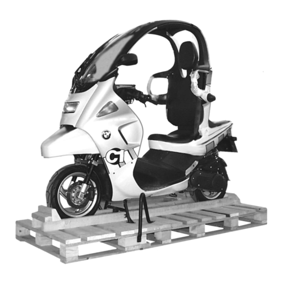
C1000340 Unpack C1 • Open shipping container at strap holes (enlarged openings) on left and right sides • Remove any enclosed packages – Luggage rack • Cut open along the line indicated (follows path of strap) • Dismantle shipping container C1000350 Attention: Loosen straps without yet removing! -
Page 29: Place C1 On Stand
Place C1 on stand Note: The easy-lift mechanism has overload protection. Fold out the stand with foot if necessary! C1000360 Note: C1000370 Note instruction plate on instrument trim! • Push up long lever (1) on easy-lift mechanism until it reaches the end of its travel –... - Page 30 C1000380 • Release and remove straps C1000390 • Remove cross member (arrow, shipping brace) 00.20...
-
Page 31: Take The C1 From The Stand
C1000400 Take the C1 from the stand Attention: Use ramp to avoid damage. Attention: The stand must be folded all the way back before • Use ramp from motorcycle hoist, etc. the vehicle is rolled down! Excessive strain can damage the easy-lift mecha- nism! Attention: Clear away any nails lying on the bottom of the ship-... - Page 32 • Check that the stand is fully retracted Note: The easy-lift mechanism has overload protection. If necessary, use your foot to retract the stand. • Push C1 off the pallet backwards Attention: Make sure the surface under the vehicle is level and firm! Do not park the C1 on slopes of more than 6°/12%, as the stand may fail to provide secure support.
-
Page 33: Check C1 For Damage
Phone: 089/382 375 82 factory equipment package and enclose +49 89 382 375 82 – BMW roadside assistance service sticker (do- mestic only) • Vehicle keys, 2 Please submit urgent queries and questions con- cerning technical issues to the C1 support staff at... -
Page 34: Fill And Charge The Battery
C1000430 Fill and charge the battery Charge current (amps) ........10 % of rated capacity (Ah) • • Open cover of rear storage compartment Use distilled water to top up the electrolyte, con- – Remove battery cover tinuing until it reaches the upper graduation •... -
Page 35: Use Bmw Moditec/Dis Plus To Access Stored Error Codes
Use BMW MoDiTeC/DIS plus to Add fuel access stored error codes • Open the seat • Pour in fuel Operation check as final inspection C1000010 • Open seat by inserting ignition key in lock at the left rear • Release backrest mount and remove backrest C1000040 •... -
Page 36: Final Cleaning
Final cleaning Vehicle delivery • Cleaning the C1 To promote optimal levels of safety and foster satis- faction, the customer should be acquainted with the C1 as part of the delivery process. Note: • Do not use steam cleaners or high-pressure spray Show/explain the following to the customer: wands. - Page 37 ......................31 1,000 km/600 miles Inspection ......................31 BMW Service ...........................31 BMW Inspection ..........................31 BMW Annual Service ........................31 Reading out BMW MoDiTeC/DIS and error codes stored in ECU ....31 (Inspections I, II, III and IV) ........................31 Engine oil change ........................32 (Inspections I, II, III and IV) ........................32 Drain engine oil and clean magnetic plug ..................32...
- Page 38 Contents Page Checking brake fluid level .....................44 (Inspections I, II and III) ........................44 Checking fluid level in the closed brake fluid reservoir ..........44 Checking fluid level in the open brake fluid reservoir ...........45 Checking brake pads and discs for wear/replacing ..........46 (Inspections II and III) ........................46 Checking brake pads for wear...
- Page 39 Contents Page Check to ensure that leading link bearing has zero play ........60 (Inspection I, IV) ..........................60 Checking steering bearing play ......................60 Check battery electrolyte level - add distilled water if necessary ....60 (Inspection IV) ...........................60 Checking battery electrolyte level ..................60 Adding distilled water ........................61 Clean/grease battery terminals if necessary...
- Page 40 00.30...
-
Page 41: Maintenance Intervals
The codes for service and maintenance intervals in Follow the instructions in the diagnosis program. this repair manual are as follows: – BMW Inspection at 1,000 km/600 miles .... I – BMW Maintenance Service every 7,500 km/4,500 miles ........II –... -
Page 42: Engine Oil Change
Replace oil filter element 11 7 661 C1000022 • Unscrew magentic oil drain plug (1) C1000330 • Clean magnet • Secure oil guard BMW No. 11 7 661 to the ex- haust • Unscrew oil filter cover bolts (arrows) BMW recommends Castrol 00.32... -
Page 43: Refill Engine With Oil
Fluids and lubricants: Engine oil ........ 1.0 l/1.76 Imp pints Brand-name HD oil, API classification SF, SG or SH; suffix letters CD or CE are approved; alternatively, brand-name HD oil with CCMC classification G4 or G5; suffix PD2 is permitted. Tightening torque: Oil filter cover .......... -
Page 44: Checking Coolant
Checking coolant Adding coolant (Inspections I and III) – Remove the backrest C1000050 C1000060 • Remove cap (1) from expansion tank (2) Note: Check coolant level only with the engine cold! Attention: • Open the seat and check the coolant level Add or refill coolant only when engine is cold. -
Page 45: Change Coolant
Change coolant Adding coolant (Inspection IV, every 2 years) Drain coolant – Remove front fairing panel – Loosen radiator cap C1170290 • Pour coolant into filler neck C1000071 • Slip hose (arrow) over screw head • Remove drain plug • Drain coolant Note: Replace drain plug seal! -
Page 46: Checking Valve Clearances
Checking valve clearances (Inspections I, II and III) Swivel out powertrain cradle • Secure front wheel C1000110 • Remove wiring from clip: - Injector - Air temperature sensor - Idle actuator - Coolant temperature sensor in cylinder head C1000090 • Remove wiring from clip (arrow): - Alternator - Ignition unit... - Page 47 Tightening torque: C1000140 Cylinder head cover ........10 Nm Strut, lower ..........21 Nm • Position vehicle jack BMW No. 00 1 570 with at- tachment BMW No. 00 1 580 at separation point • Raise the vehicle slightly •...
-
Page 48: Checking Valve Clearances
Record the valve clearances • and adjust valve clearance as indicated (replace • Open hose clamp (arrow) with pliers valve lifters) BMW No. 17 5 500 • Unscrew cylinder head cover bolts (1) Specified clearances: IV left IV right EV left... -
Page 49: Adjusting Valve Clearances
11 7 651 C1000220 • Remove Allen bolt adjacent to starter and use special bolt, BMW No. 11 7 651, to lock at TDC Note: Because the round cover plate can rotate against C1130010 the gear, the TDC mark should always be made on the gear itself - not on the cover plate •... - Page 50 Note: Watch bolt length and take care to install in correct positions, lettering is to the outside, use coloured marker to identify end as necessary! C1000231 • Release chain tensioner bolt (arrow) C1000190 • Detach mounts (arrows) from chain guide and re- move Note: The camshafts can also be removed and installed...
- Page 51 • Subtract negative difference of bucket (old) • Add positive difference of bucket (old) Note: • Note the length of the bolts used to attach the cam- Note sizes of available bucket tappets shaft bearing cap! Note: The bucket tappets are available in sizes ranging from 2.50 mm (0.09842 in) to 3.20 mm (0.12598 in) in 5/100ths graduations.
-
Page 52: Replace Spark Plug
Install chain tensioner ( 11.33) – Remove left service cover Attention: Remove TDC set bolt, BMW No. 11 7 651. 12 3 531 • Turn the engine over several times by hand • Check valve clearance and adjust as necessary... -
Page 53: Replacing Air Cleaner Element
Replacing air cleaner element Empty drain pipe from intake-air plenum chamber (Inspections II and III) (Inspection IV) • Empty the drain pipe from the air cleaner housing C1000130 C1130010 • • Remove fasteners (1) securing cover to air filter Remove plug (arrow) and allow oil which has housing drained out to escape •... -
Page 54: Checking Brake Lines
Checking brake lines • Turn the handlebars at full left-hand lock (Inspections II and III) Note: The volume of the brake fluid (MIN/MAX) is sufficient for lining thicknesses from new to the wear limit. It is Attention: not normally necessary to top up the fluid to accom- Refer to and observe the precautions for handling modate lining wear. -
Page 55: Checking Fluid Level In The Open Brake Fluid Reservoir
Checking fluid level in the open brake fluid reservoir The procedure for checking the level in the left brake fluid reservoir is described below. The procedure for checking the level in the right brake fluid reservoir is basically the same. Attention: Do not allow brake fluid to come into contact with painted parts of the motorcycle - brake fluid attacks... -
Page 56: Checking Brake Pads And Discs For Wear/Replacing
Checking brake pads and discs for Rear brake pads wear/replacing (Inspections II and III) Checking brake pads for wear Warning: Never allow brake pads to wear below the minimum specified thickness! Always replace pads as a complete set! Front brake pads C1340360 •... -
Page 57: Replacing Brake Pads
If the brake pads/pistons cannot be forced back in • this way, this can indicate a defect in the brake sys- Remove dowel pin (1) with drift punch or pliers, tem! BMW No. 34 1 541 • Remove the brake pads. When installing: •... -
Page 58: Rear Brake
Remove the cotter pin (1) from dowel pin (2) • Remove dowel pin (2) with extractor, BMW No. 34 1 570 • Attention: Pull out the brake pads toward the rear Avoid scratching or otherwise damaging the wheel... -
Page 59: Checking The Brake Discs
Checking the brake discs • Carefully check the brake discs for cracking, damage, deformation and scoring C1340480 • Remove support plate (1) to the inside C1340420 When installing: • While installation is basically a reversal of the re- • moval process, careful attention should be di- Measure the thickness of the brake discs at sev- rected toward the following operations: eral points with a caliper gauge... -
Page 60: Replacing Brake Fluid
BMW MoDiTeC/DIS plus with the ABS control unit • Force the pistons all the way back into the brake toolbox. calipers Failure to use the BMW MoDiTeC/DIS plus results in a hazard of residual air remaining in the ABS control circuits. Note: •... -
Page 61: Bleed The Front Brake Circuit
- brake fluid attacks BMW MoDiTeC/DIS plus with the ABS control unit paint! toolbox. Failure to use the BMW MoDiTeC/DIS plus results in a hazard of residual air remaining in the ABS control Drawing off brake fluid/forcing back brake pis- circuits. -
Page 62: Bleeding Rear Brake Circuit
On vehicles with ABS the brake service operations described in the repair manual must be supplement- ed by bleeding operations using the BMW MoDiTeC/DIS plus with the ABS control unit toolbox. Failure to use the BMW MoDiTeC/DIS plus results in a hazard of residual air remaining in the ABS con- trol circuits. -
Page 63: Check Belt
Install belt together with driven variator • Check by turning variator manually to ensure that • Use retainer, BMW No. 11 7 521, to apply coun- belt is not trapped terpressure and remove the attachment from the driven variator •... -
Page 64: Checking Clutch Lining
Checking clutch lining Clean variator filter screen (Inspection III) (Inspections II and III) C1110540 C1000240 • • Remove bell housing; use puller if necessary Remove fasteners (1) • • Check clutch plate lining replace if necessary Remove vent cover Note: Replacing driven variator without clutch ( 24.6). -
Page 65: Drive Variator
11 7 521 C1000440 C1000291 Note: The nut is secured with thread-locking compound! • Undo nut (arrow) using retainer BMW No. 11 7 521 • Remove outer washer and drive variator with spacer • Clean locking compound from threads on crank- shaft... - Page 66 When installing: • While installation is basically a reversal of the re- moval process, careful attention should be di- rected toward the following operations: C1000480 C1111300 Note: The rollers in the frame may display flat spots within • the wear limits! Evenly apply approximately 20 g (0.7 oz) of Wear within the specified wear limits is acceptable! grease to the contact path of the inner plate...
-
Page 67: Check And Clean Drive Variator (Unlubricated Version)
Check and clean drive variator (unlu- bricated version) (Inspection II, III) (unlubricated version) C1000470 Note: C1000450 Flat spots on the rollers that do not not exceed the wear limits are acceptable! Wear within the specified limits is acceptable! Visible and palpable contact tracks (arrows) caused by motion of rollers through their travel paths are ac- ceptable! •... -
Page 68: Replacing Complete Drive Variator
Check action of transfer element Note: The nut is secured with thread-locking compound! • Torque specification: Use retainer BMW No. 11 7 521 to undo outside Drive variator mount plate, then remove drive variator with spacer • (+ LOCTITE 243)........... 60 Nm Clean locking compound from crankshaft Variator cover .......... -
Page 69: Checking Wheel Bearing Float
Checking wheel bearing float When installing: • Observe installation instructions for lubricated 00.56) and unlubricated variator ( 00.58) • Spray shaft as necessary (Inspection III) Fluids and lubricants: Shaft ........ Klüber paste 46 MR 401 Note: Mount for drive variator ....LOCTITE 243 Check bearing float with cold bearing only. -
Page 70: Check To Ensure That Leading Link Bearing Has Zero Play
Check to ensure that leading link Check battery electrolyte level - add bearing has zero play distilled water if necessary (Inspection I, IV) (Inspection IV) Checking steering bearing play • Relieve load on front wheel Warning: Battery acid is extremely caustic. Protect your eyes, face, hands, clothing and the paintwork! Attention:... -
Page 71: Adding Distilled Water
Checking Bowden cables Adding distilled water (Inspections III and IV) • Check Bowden cables for damage from rubbing and abrasion • Check freedom of movement and adjust, if nec- essary ........... See Group 32 Throttle cable: • Move the handlebars all the way from left to right and ensure that throttle valve does not move Checking easy-lift mechanism C1610030... -
Page 72: Checking Windscreen Washer
Use a screwdriver to adjust nozzles C1720050 • Top up windscreen-washer fluid • Use test gauge, BMW No. 72 5 501, to preten- Check windscreen wiper sion release lever • Engage seat belts in their buckles with an audi- (Inspections II, III and IV) ble click •... -
Page 73: Examine Crash Elements
13 3 010 essary ........... See Group 46 Measure shoulder bar C1160090 • Use clamp, BMW No. 13 3 010, to seal off the fuel lines • Open hose clamp with pliers, BMW No. 17 5 500 • Replace fuel filter •... -
Page 74: Replacing Boot In Brake-Control Assembly (Master Cylinder), Only With Optional Abs
Replacing boot in brake-control When installing: • assembly (master cylinder), only While installation is basically a reversal of the re- moval process, careful attention should be di- with optional ABS rected toward the following: (Inspection III) every 30,000 km (18,000 miles ) Attention: For greater clarity the illustrations show the brake- Observe correct sequence for individual parts! -
Page 75: Check Mounts
Engine mounts – Rear wheel – Front wheel Attention: Remove the vehicle stand, BMW No. 00 1 570. • Attention: Check wheels and tyres • Never re-use the original nut on the rear wheel! Check tyre pressures and correct if necessary... - Page 76 00.66...
- Page 77 11 Engine Contents Page Technical Data ..........................3 C1 engine ............................9 C1 lubrication ..........................10 C1 drivetrain ..........................11 # Operations performed with powertrain cradle installed ........12 Swivel out powertrain cradle ....................12 Lock engine at TDC ........................14 # Checking valve clearances ....................
- Page 78 Contents Page Inlet and exhaust valve .......................27 Removing valves ..........................27 Check valve guide for wear .......................29 Check valve seat for wear ........................30 Regrinding valve seats ........................30 Check valve for wear .........................31 Check valve springs for wear ......................31 Install valves ............................32 # Check timing chain ........................33 # Replacing chain tensioner...
- Page 79 Winter operation 5W-40 Oil pressure: bar (psi) ≥ 0.5 (7.11) (oil temperature 80 °C/176 °F) (idle) 7,500 rpm bar (psi) 3 (43.54) Max. allowed oil consumption l/100 km 0.01 (1.76/1.05) (miles per Imp pint/miles per US quart) BMW recommends Castrol 11.3...
- Page 80 Technical Data C1 200 Crank assembly with conrod Main bearing bore diameter Installed dimension mm (in) Wear limit mm (in) 32.07 (1.2626) Crankshaft - main bearing play Installed dimension mm (in) 0.030…0.070 (0.001…0.002) Wear limit mm (in) 0.10 (0.0039) Main bearing diameter mm (in) 32.015…32.025 (1.2604…1.2608) Wear limit mm (in) 32.01 (1.2602)
- Page 81 Technical Data C1 200 Camshaft Inlet ° 276 Exhaust ° 264 Bearing cap Bearing journal diameter mm (in) 18.01…18.03 (0.709…0.7099) Wear limit mm (in) 18.05 (0.7106) Inlet camshaft Bearing journal diameter mm (in) 17.969…17.980 (0.7074…0.7078) Wear limit mm (in) 17.96 (0.7070) Exhaust camshaft mm (in) 17.969…17.980 (0.7074…0.7078) Bearing journal diameter...
- Page 82 Technical Data C1 200 Valve guide Inlet/exhaust inside diameter mm (in) 4.002…4.015 (0.1576…0.1581) Wear limit mm (in) max. 0.5 (0.0197) Projection mm (in) 9.8…10.2 (0.3858…0.4016) Valve seat angle Inlet ° 45 Exhaust ° 45 Included angle between valves Inlet ° 16 Exhaust °...
- Page 83 Technical Data C1 200 Piston pin Extl. dia. mm (in) 14.997…15.000 (0.5904…0.5906) Wear limit mm (in) 14.99 (0.5902) Installed clearance Wear limit mm (in) 0.04 (0.0016) Radial play mm (in) 0.005…0.018 (0.0002…0.0007) Wear limit mm (in) 0.03 (0.0012) Piston wristpin bore diameter mm (in) 15.003…15.008 (0.5907…0.5909) Wear limit mm (in) 15.03 (0.5917)
- Page 84 Technical Data C1 200 Direction of installation Arrow on piston crown points toward exhaust Cylinders Bore Cylinder “A” mm (in) 56.388…56.398 61.988…61.997 (2.2200…2.22204) (2.4404…2.4408) Cylinder “B” mm (in) 56.402…56.412 62.003…62.012 (2.2206…2.2209) (2.4411…2.4414) Timing chain Distance from sealing face to chain tensioner plunger Wear limit mm (in) 6 (0.2362) Water pump...
-
Page 85: C1 Engine
C1 engine R11C160 engine 11.9... -
Page 86: C1 Lubrication
C1 lubrication R11C161 lubrication 11.10... -
Page 87: C1 Drivetrain
C1 drivetrain R24C161 TSS 11.11... -
Page 88: Operations Performed With Powertrain Cradle Installed
# Operations performed with power- Swivel out powertrain cradle train cradle installed For enhanced clarity some of the illustrations show the components with the powertrain cradle re- moved. Note: Operations identified by # can also be carried out • with the powertrain cradle installed. Secure front wheel Left side •... - Page 89 Coolant temperature sensor to cylinder head 33 1 531 00 1 580 00 1 570 C1000140 • Position vehicle hoist, BMW No. 00 1 570, with C1000120 attachment BMW No. 00 1 580, at separation point • • Release coolant hose from clip at injector and Slightly raise vehicle with lifter •...
-
Page 90: Lock Engine At Tdc
Lock engine at TDC 11 7 651 C1000220 • Undo the Allen bolt adjacent to the starter and use set bolt, BMW No. 11 7 651, to lock the en- gine at TDC C1130010 • Loosen hose clamp (arrow) on intake-air plenum chamber 11.14... -
Page 91: Checking Valve Clearances
# Checking valve clearances 11 34 004 When installing: • Install the cylinder head cover before installing – Remove left and right service covers the powertrain cradle ............See Group 46 – Swivel out powertrain cradle ( 11.12) – Remove cylinder head cover ( 11.34) Attention: –... -
Page 92: Adjusting Valve Clearances
(0.0059) (0.0059) (used) bearing caps/camshafts ( 11.37) 0.01 -0.05 Difference (0.00039) (-0.0019) Attention: Remove TDC set bolt, BMW No. 11 7 651! Bucket, 2.80 2.80 measured • Turn the engine over several times by hand (0.1102) (0.1102) (used) • Recheck valve clearances Bucket 2.81... -
Page 93: Removing And Installing Powertrain Cradle
Removing and installing 11 00 060 powertrain cradle 17 5 500 – Remove left service cover – Remove the right rear side section C1110140 • Open hose clamps at return hose and in front of distributor – Remove silencer (muffler) ............See Group 18 C1000080 –... - Page 94 Detach the spring struts from the powertrain cra- dle and tie up out of the way • Using extension, BMW No. 11 0 652, and stand, BMW No. 00 1 490, pull powertrain cradle to the rear to remove 11.18...
-
Page 95: Replacing Grooved Ball Bearing For Engine Mount
Replacing grooved ball bearing for # Replacing ignition cover 11 11 015 engine mount – Remove the right rear side panel • – Housing halves separated Drain engine oil • • Using a pipe D=24.5 mm (0.9646 in) or a 19 mm Remove fastener securing silencer to auxiliary (0.7480 in) socket and working from the inside, swing arm... -
Page 96: Replacing Oil Pump
Replacing oil pump When installing: • The outer rotor bears a punch mark for identifica- 11 11 300 Removing and installing oil pump tion – Remove reluctor ( 12.8) C1110290 C1110280 • Turn over the engine until the attachment bolts Note: (arrows) come into view Make sure that punch mark is toward inside of pump... -
Page 97: Measuring Oil Pump
Measuring oil pump C1110280 C1110300 • Remove circlip and washer (arrow) • • Check tooth edges of oil pump gear for deforma- Press water pump gear out of fitting in needle tion roller • Measure protrusions of needle roller • Check runout of oil pump gear relative to shaft •... -
Page 98: Replacing Shaft Oil Seals
Coat shaft seal extruded edges with MOLYKOTE 111 Attention: Install shaft seals with flat surfaces facing each oth- • Use drift punch, BMW No. 11 7 611, and shim to install first shaft seal • Install shim (arrow) • Install second shaft seal without shim... -
Page 99: Install Water Pump
• Install water pump Press water pump gear onto needle roller • Prior to installation coat the inner extruded edge seals with MOLYKOTE 111 Note: • Fill cavity with MOLYKOTE 111 Water pump gear must engage with an audible click •... -
Page 100: Replacing Oil Filter
Spring length......13.4 mm (0.5276 in) C1000030 When installing: • Installation is the reverse of the removal proce- • Place drain plate, BMW No. 11 7 661, on ex- dure • haust pipe Install with new seal • Remove securing screws •... -
Page 101: Replacing Filter Screen
Installing crankshaft oil seal Torque specification: Drain plug............. 30 Nm 11 7 591 C1110880 • Use assembly punch, BMW No. 11 7 591, to in- stall the oil seal with the extruded edge on the in- side 11.25... -
Page 102: Cylinder Head
(+ Loctite 243) ..........15 Nm 11 3 251 C1111230 • Use rubber suction cup, BMW No. 11 3 251, to extract the bucket tappets (arrows) • Inspect bucket tappets and their guides to en- sure that all components are in good condition... -
Page 103: Inlet And Exhaust Valve
Inlet and exhaust valve When installing: • While installation is basically just a reversal of the removal procedure, special attention should be devoted to the following points: Removing valves – Swivel out powertrain cradle ( 11.12) Attention: – Remove cylinder head cover ( 11.34) Install bucket tappets in their original locations, –... - Page 104 Screw cylinder head to baseplate, BMW No. 11 7 561 • Tighten support bar, BMW No. 11 7 563, knurled nut, BMW No. 11 7 562, pressure rod, BMW No. 11 7 566, and pressure plate 11 1 480 11 7 564...
-
Page 105: Check Valve Guide For Wear
.............. (0.0019 in) C1111270 • Measure maximum tilt "K" with dial gauge, BMW No. 00 2 510, at a right angle to the valve axis, at a transverse angle to the camshaft axis Wear data: Tilt "K" ..........max. 0.5 mm .............. -
Page 106: Check Valve Seat For Wear
Check valve seat for wear Regrinding valve seats • Apply Prussian blue or similar paste to the valve seat inserts • Install the correct valve and turn under gentle pressure 70° 45° 20° C1111190 • Regrind valve seat with rotary valve seat grinder C1111200 Note: •... -
Page 107: Check Valve For Wear
Check valve for wear Check valve springs for wear F110190 C1111240 • • Check stem diameter and seat width on valve Check valve springs for breakage, deformation spring cap and loss of tension • Check valve for runout Wear dimensions C1: Wear dimension for valve: Extended spring length "L"... - Page 108 While installation is basically just a reversal of the removal procedure, special attention should be Attention: devoted to the following points: Remove TDC set bolt, BMW No. 11 7 651 • Turn the engine over several times by hand Attention:...
-
Page 109: Check Timing Chain
# Check timing chain # Replacing chain tensioner 11 31 080 For enhanced clarity some of the illustrations show – Turn crankshaft to top dead centre and secure in the components with the powertrain cradle removed this position ( 11.14) –... -
Page 110: Cylinder Head Cover Removal And Installation
Install with no oil on gasket or in recess within the cylinder head cover! Torque specification: Cylinder head cover ........10 Nm C1000150 • Open hose clamp (arrow) with pliers, BMW No. 17 5 500. • Undo attachment bolts (1) on valve cover 11.34... -
Page 111: Camshaft, Camshaft Sprocket, Camshaft Bearing Cap
Camshaft, camshaft sprocket, camshaft bearing cap Removing and installing camshaft sprockets For enhanced clarity some of the illustrations show the components with the powertrain cradle removed – Swivel out powertrain cradle ( 11.12) – Remove cylinder head cover ( 11.34) –... -
Page 112: Camshaft Bearing Cap/Camshaft Removal, Installation, Replacement
Install chain tensioner – Removing camshaft sprockets ( 11.35) Attention: Remove TDC set bolt, BMW No. 11 7 651! Note: Make sure that the timing chain does not drop into • Turn the engine over several times by hand the housing. Use a retainer to keep timing chain ten- –... - Page 113 Make sure that the camshafts turn easily and smoothly • Install chain tensioner Attention: Remove TDC set bolt, BMW No. 11 7 651! • Turn the engine over several times by hand • Check valve clearances and adjust as required...
-
Page 114: Checking Camshafts
Note: • Lobe height mweasurement Watch installation positions and bolt lengths, • Use Plastigage (arrow), BMW No. 00 2 590, to lettering to the outside, identify with coloured mark- check clearance of camshaft after installation er as necessary! Wear data: Inlet lobe height....min. -
Page 115: Replacing Guide Rail
When installing: 11 31 112 Replacing guide rail • While installation basically consists of performing the dismantling operations in reverse sequence, For enhanced clarity some of the illustrations show special attention should be directed toward the the components with the powertrain cradle re- following additional points: moved. -
Page 116: Timing Chain Removal, Installation, Replacement
Cylinder head removal and installation When installing: • Remove all traces of old thread-locking com- • pound from the threads Operations with powertrain cradle installed: • Coat threads of collar screw with Loctite and in- – Drain coolant stall ............See Group 17 –... -
Page 117: Cylinder Liner Removal
Use a shop towel or some similar insulating material • Tighten collar nuts in cross pattern using socket to prevent the connecting rod from damaging the attachment, BMW No. 11 7 541 cylinder bore during the removal process! • Use shop towels to guard the bore against dam- Torque specification: •... -
Page 118: Replacing Stud Bolts
11 7 633 C1111000 • Secure crankshaft at TDC ( 11.14) • Use ring squeezer sleeve C1: BMW No. 11 7 632 C1 200: BMW No. 11 7 633 C1111020 • Remove circlip C1111010 Note: Do not damage the piston! •... -
Page 119: Replacing Piston Rings
Piston ring gap: C1111030 Compression ring...... 0.7 mm (0.0276 in) Chamferred compression ring ... 0.8 mm (0.0315 in) • Use drift punch, BMW No. 11 7 631, to drive out Oil scraper ring......1.0 mm (0.0394 in) wristpin Ring thickness: When installing: Compression ring.... -
Page 120: Checking Piston Dimensions
Checking piston dimensions C1 piston dimensions: – Removing cylinder Piston "A" Ø ......56.37 mm (2.2193 in) Piston "B" Ø ......56.38 mm (2.2197 in) Piston C1 Piston dimensions C1 200: Piston "A" Ø ......61.97 mm (2.4398 in) Piston "B" Ø ......61.98 mm (2.4402 in) Wear values: Installed clearance .... -
Page 121: Removing Crankshaft
Removing crankshaft Measuring end float – Removing powertrain cradle ( 11.17) – Support in assembly stand – Remove starter motor ( 12.7) – Remove drive variator ( 24.7) – Remove reluctor ( 12.8) – Remove cylinder head cover ( 11.34) –... -
Page 122: Measuring Housing
C1111110 • Support bearing seat with spacer tube D=36 mm (1.4173 in) h=30 mm (1.1811 in) • Use drift punch, BMW No. 11 7 621, to press bearing shells from the outside to the inside II II III III C1111100 Measurement planes: 1 90°... -
Page 123: Installing Bearing Shells
• Support bearing seat with spacer tube D=36 mm (1.4173 in) h=30 mm (1.1811 in) • Use drift punch, BMW No. 11 7 622, to press bearing shells from the outside in, continuing un- Attention: til they seat Lube-oil bore in housing must be aligned with bore... -
Page 124: Replacing Cylindrical Pin For Starter Double Gear
Replacing cylindrical pin for starter double gear Installing crankshaft C1111140 C1111150 Wear data: Cylinder pin Ø ......9.95 mm (0.3917 in) Attention: • Heat surrounding zone to approx. 100 °C Check end float if crankshaft or crankcase has been (212 °F) and use vise grips to remove cylindrical replaced! •... -
Page 125: Joining Halves Of Crankcase
Joining halves of crankcase Attention: Make sure that all bearings of crankshaft are ade- quately lubricated! C1111170 • Add 0.45 mm (0.0177 in) to both measurement results and the thickness of the gasket (com- pressed) • Check installed width of crankshaft •... - Page 126 11.50...
-
Page 127: Engine Electrics
12 Engine electrics Contents Page Technical Data ..........................3 Replacing spark plug/ignition cable ..................5 Replacing spark plugs ........................5 Replacing ignition cable ......................6 Replacing ignition coil .......................6 Replacing starter ..........................7 Replacing alternator ........................7 Replacing TDC trigger .......................8 Reluctor removal and installation ..................8 Replacing one-way clutch ......................... - Page 128 12.2...
-
Page 129: Technical Data
Permanent-magnet motor Power rating kW (bhp) 0.6 (0.82) Spark plug NGK CR 8EB Thread metric M 10 x 1 Electrode gap mm (in) 0.8 (0.0315) Wear limit mm (in) 0.9 (0.0354) Ignition Ignition system BMW engine-management system (BMW-Motor-Steuerung, BMS) 12.3... - Page 130 12.4...
-
Page 131: Replacing Spark Plug/Ignition Cable
– Remove left service cover ............See Group 46 C1120030 • Use spark plug wrench, BMW No. 12 3 531, to remove spark plug When installing: • While installation is basically a reversal of the re- moval process, careful attention should be di-... -
Page 132: Replacing Ignition Cable
Replacing ignition cable Replacing ignition coil 12 12 085 12 13 000 – Remove rear left side panel ............See Group 46 Attention: Switch off ignition; disconnect earth (ground) cable from battery and insulate it! – Remove rear left side panel ............See Group 46 C1120010 •... -
Page 133: Replacing Starter
Replacing starter Replacing alternator 12 41 020 12 11 070 – Removing ignition trigger cover ............See Group 11 Attention: Disconnect ground cable from battery and insulate • Remove intake-air plenum chamber from rear mudguard • Remove fasteners securing rear mudguard C1110190 •... -
Page 134: Replacing Tdc Trigger
..........(0.315 ± 0.0157 in) 11 6 502 Torque specification: Tapite bolts (+ Loctite 243) ......6 Nm C1110220 • Use removal bolt, BMW No. 11 6 502, to press off reluctor with one-way clutch • Check taper and keyway of reluctor 12.8... - Page 135 When installing: • Remove all traces of old thread-locking com- pound from the threads C1110240 • Install securing screw with washer: coat threads C1110230 of securing screw with Loctite 243 • Install Woodruff key parallel to crankshaft (arrow), Fluids and lubricants: not parallel to taper Bolt ............LOCTITE 243 •...
-
Page 136: Replacing One-Way Clutch
12 11 077 Replacing one-way clutch Replacing starter double gear – Remove cover – Remove reluctor C1110260 C1110250 • Check bearing bore • Check teeth for distortion, wear and chipping • • Loosen the attachment screws on the reluctor Check straight pin housing by supporting the bottom in a vise with protective padding on the jaws Wear data:... -
Page 137: Replacing One-Way Clutch Gear
Replacing one-way clutch gear C1110270 • Measure bearing bore • Check teeth for distortion, wear and chipping • Check friction face for wear Wear data: Internal diameter ......max. 22.05 mm ............(max. 0.8681 in) Note: Before installing one-way clutch, check Woodruff key! •... - Page 138 12.12...
-
Page 139: Fuel Preparation And Control
13 Fuel preparation and control Contents Page Removing and installing air filter housing ..............3 Removing and installing intake-air plenum chamber ..........3 Removing and installing throttle-valve assembly ............5 Injector ...............................6 Removing and installing injectors ......................6 Replacing injector ..........................6 Replacing injection nozzle holder ......................7 Replacing BMS control unit ....................7 13.1... - Page 140 13.2...
-
Page 141: Removing And Installing Air Filter Housing
Removing and installing air Removing and installing 13 72 110 13 72 128 filter housing intake-air plenum chamber – Remove air filter housing C1130010 C1130090 • • Remove fasteners (arrows) Remove fastener (arrow) C1130100 C1130040 • • Loosen hose clamps (arrow) on intake-air ple- Remove fasteners (arrows) num chamber 13.3... - Page 142 00 1 570 C1130030 C1130050 • • Disconnect plug (3) Use hoist, BMW No. 00 1 570, to raise C1 slight- • Open hose clamp (2) with pliers, • BMW No. 17 5 500 Detach the spring struts from the powertrain cra- •...
-
Page 143: Removing And Installing Throttle-Valve Assembly
Disengage throttle cable from bracket and cam disc C1130080 • Release hose clamp (arrow) on intake air duct with pliers, BMW No. 17 5 500 • Pull up rear of throttle valve assembly whilst si- multaneously separating from intake-air duct •... -
Page 144: Injector
C1130110 • Remove spring clip (arrow) • Remove injector • Use hose clamps, BMW No. 13 3 010, to close off fuel hoses (arrows) When installing: • • Undo plug-in connection (3) Installation is the reverse of the removal proce- •... -
Page 145: Replacing Bms Control Unit
C1130110 the plug to the right • Use hose clamps, BMW No. 13 3 010, to close off fuel hoses (arrows) • Use pliers, BMW No. 17 5 500, to release hose clamps •... - Page 146 13.8...
-
Page 147: Fuel Tank And Lines
16 Fuel tank and lines Contents Page Technical Data ..........................3 Removing and installing fuel tank ..................5 Replacing fuel filter ........................7 Fuel pump unit ..........................8 Removing, installing fuel pump assembly ................8 16.1... - Page 148 16.2...
- Page 149 Technical Data Tank capacity l (Imp 9.7 (17.1/10.3) pint/US quart) including reserve of l (Imp 2.5 (4.4/2.6) pint/US quart) Fuel specification Super (premium), unleaded, 95 octane (RON) Fuel pump Type Peripheral-gear pump Rated voltage V 12 Operating voltage V 7…14 Fuel pressure bar (psi) 2.5 (35.57) operating pressure 3.8 (54.07) max...
- Page 150 16.4...
- Page 151 Release tunnel panel on right from front anchor- age point C1160011 • Warning: Use hose clamps, BMW No. 13 3 010, to close Comply with safety precautions when handling or off fuel hoses (arrows) • working with fuel; note that the fuel lines are pressu- Use pliers, BMW No.
- Page 152 C1160040 C1160061 • • Cut through cable tie (arrow) of connecting cable Use hoist, BMW No. 00 1 570, and attachment, for stand switch BMW No. 00 1 580, to lift vehicle Additional, applies to vehicles with ABS: – Remove the ABS control unit ............See Group 34...
- Page 153 Torque specification: Bracket, fuel tank to frame ......9 Nm Bracket, washer fluid reservoir/ABS ECU to frame ............9 Nm Replacing fuel filter 16 12 008 – Open the seat – Remove left service cover ............See Group 46 C1160070 Warning: Comply with safety precautions when handling or •...
- Page 154 – Remove top tunnel panel C1160090 ............See Group 46 • Use hose clamps, BMW No. 13 3 010, to close off fuel hoses (arrows) • Release hose clamps (1) with pliers, BMW No. 17 5 500 When installing: •...
- Page 155 Fit the seal and install the fuel-pump unit in the fuel tan C1160011 16 1 721 • Use hose clamps, BMW No. 13 3 010, to close off fuel hoses (arrows) • Slacken hose clamps with pliers, BMW No. 17 5 500 •...
- Page 156 16.10...
- Page 157 17 Radiator Contents Page Technical Data ..........................3 Coolant circuit ..........................5 Removing and installing coolant hoses ................7 Opening hose clamps ........................7 Closing hose clamps ........................7 Replacing feed hoses to radiator .....................7 Hose between radiator and elbow .......................7 Hose between elbow and coolant pipe ....................7 Hose between elbow and refill reservoir ....................8 Vent hose ............................8 Replacing return hose to radiator...
- Page 158 Contents Page Removing and installing radiator with fan ..............17 Removing and installing front frame with radiator ............17 Removing and installing radiator with fan shroud in front frame ......18 Replacing radiator ........................19 Replacing fan ..........................19 Replacing air duct ........................
-
Page 159: Technical Data
Technical Data Cooling-system capacity Total capacity l (Imp 1.45 (2.55/1.53) pint/US quart) Cooling circuit l (Imp 1.25 (2.20/1.3214), top-up capacity approx. 1.2 l (2.1123/1.2685) pint/US quart) Expansion tank l (Imp 0.2 (0.35/0.21) pint/US quart) Coolant Use only nitride-free extended-duty antifreeze with corrosion inhibitor Mixture ratio 50% antifreeze... - Page 160 17.4...
-
Page 161: Coolant Circuit
Coolant circuit C1179010 17.5... - Page 162 17.6...
-
Page 163: Removing And Installing Coolant Hoses
17 12 150 Hose between radiator and elbow 17 5 500 C1170001 • Release all hose clamps with 17 5 500 pliers, BMW No. 17 5 500 C1170020 Closing hose clamps • Remove coolant hose (arrow) 17 12 154 Hose between elbow and coolant pipe... -
Page 164: Hose Between Elbow And Refill Reservoir
Replacing return hose to radi- 17 12 159 Hose between elbow and refill reser- 17 12 175 voir ator – Remove front fairing panel – Remove left side trim panel ............See Group 46 – Drain coolant ( 17.14) 17 12 180 Hose between radiator and coolant pipe 17 5 500 C1170040... - Page 165 C1170070 Replacing coolant hoses on engine 11 53 120 Replacing thermostat – Remove engine coolant hoses • – Open the seat Remove thermostat (4) ............See Group 52 – Remove left service cover Install engine coolant hoses • ............See Group 46 Installation is the reverse of the removal proce- –...
-
Page 166: Removing And Installing Coolant Pipes
C1170080 • Remove fasteners (arrows) from frame on the right • Release hose clamps (1) with pliers, BMW No. 17 5 500 17 5 500 C1170090 • Remove fasteners (arrows) from frame on the left • Release hose clamps (2) with pliers, BMW No. -
Page 167: Installing Coolant Pipes
Coolant pipe to frame ........9 Nm C1170111 • Remove fastener (arrows) from front frame • Release hose clamps (1) with pliers, BMW No. 17 5 500 17 5 500 C1170090 • Remove fasteners (arrows) from frame • Release hose clamps (1) with pliers, BMW No. -
Page 168: Replacing Vapour Discharge Hose
17 12 200 If the expansion tank still contains coolant: • Clamp vapour discharge hose with hose clamp, BMW No. 13 3 010 • Pull the vapour discharge hose out toward the – Remove front fairing panel rear until the end is approximately half-way along –... -
Page 169: Removing And Installing Expansion Tank
Removing and installing 17 11 087 When installing: • expansion tank Installation is the reverse of the removal proce- dure • Adding coolant • – Open the seat After running the engine check the coolant level – Remove the backrest and top up if necessary ............See Group 52 Note:... -
Page 170: Changing Coolant
Changing coolant 17 00 035 Note: Change the coolant at least every 2 years. Draining coolant – Remove front fairing panel – Swing the headlight forward and down ............See Group 46 – Open the seat ............See Group 52 C1170160 • Unscrew drain plug (arrow) from engine C1170150 •... -
Page 171: Draining Coolant From Return Line
• Remove moulded return hose (4) from bracket (3) • Release hose clamps (1) with pliers, BMW No. 17 5 500 • Disconnect moulded hose (4) from coolant pipe When installing: • Installation is the reverse of the removal proce- dure •... -
Page 172: Filling Expansion Tank With Coolant
• Install the cap on the expansion tank adapter, BMW No. 17 5 520, and spring clamp, BMW No. 17 5 525, to refill bag • Pressure-test the system; the pressure must re- main unchanged for at least 5 minutes Setting: Test pressure ........ - Page 173 • Disconnect plug (1) from fan motor • Disconnect plug (2) from horn • Release right hose clamp (arrow) with pliers, BMW No. 17 5 500 C1170200 17 5 500 • Disconnect plug (1) from headlight • Remove parking light (2) from its socket C1170060 •...
-
Page 174: Removing And Installing Radiator With Fan
Remove front frame with radiator C1170220 • Release the hose clamp (arrow) securing the va- pour discharge hose with the assistance of pli- C1170240 ers, BMW No. 17 5 500 • Disconnect vapour discharge hose (1) • Remove fasteners (1) securing air duct •... -
Page 175: Replacing Radiator
Replacing fan When installing: 17 40 000 • While installation is basically a reversal of the re- moval process, careful attention should be di- – Remove radiator rected toward the following operations: Attention: Inspect for abrasion in fan/brake hose! Torque specification: Front frame mount ......... -
Page 176: Replacing Refill Reservoir
Refill reservoir mount ........9 Nm C1170290 • Remove fasteners (2, 4) from refill reservoir • Release hose clamps (arrows) with pliers, BMW No. 17 5 500 • Pull refill reservoir to one side • Disconnect vapour discharge hose (1) from refill reservoir •... - Page 177 18 Exhaust system Contents Page Technical Data ..........................3 Removing and installing silencer heat shield ...............5 Removing and installing silencer system ................5 Removing and installing oxygen sensor ................7 18.1...
- Page 178 18.2...
- Page 179 Technical Data Silencer assembly Exhaust-emissions control 3-way catalytic converter Silencer (muffler) Reflection/absorption silencer manufactured in of rustproof stainless steel 18.3...
- Page 180 18.4...
- Page 181 Removing and installing Removing and installing 18 12 212 18 00 020 silencer heat shield silencer system C1180001 C1180021 • • Remove 4 fasteners (arrows) Open cable clip (arrow) • • Remove exhaust heat shield Disconnect plug (1) from the oxygen sensor When installing: •...
- Page 182 When installing: • While installation is basically a reversal of the re- moval process, careful attention should be di- rected toward the following: Attention: When installing, make sure that the oxygen sensor cable is correctly routed and secured! Note: Replace the cylinder head gasket! C1180041 Torque specification: •...
- Page 183 • Install oxygen sensor by hand • Tighten the oxygen sensor with socket wrench insert, BMW No. 11 7 020 C1180021 Attention: • Open cable clip (arrow) When installing, make sure that the oxygen sensor •...
- Page 184 18.8...
- Page 185 21 Clutch Contents Page Technical Data ..........................3 Centrifugal coupling ........................5 Checking clutch ..........................5 Removing/replacing clutch ......................5 Check spring ............................6 Install clutch ............................7 21.1...
- Page 186 21.2...
-
Page 187: Technical Data
Technical Data Clutch Clutch drum Intl. dia. mm (in) 134.0…134.2 (5.2756…5.2835) Wear limit mm (in) 134.6 (5.2992) Clutch lining Thin point mm (in) 3.10 (0.1220) Wear limit mm (in) 2.52 (0.0992) Thick point mm (in) 4.80 (0.1890) Wear limit mm (in) 4.00 (0.1575) Spring Spring length mm (in) 174 (6.8504) - Page 188 21.4...
-
Page 189: Centrifugal Coupling
C1110381 Removing/replacing clutch • Release clutch drum nut with retainer, BMW No. 11 7 521 • Remove clutch drum, using a puller if necessary • Clean and dry clutch drum and clutch and check... -
Page 190: Check Spring
Wear data: • Allow the hooks on the holder, Length "x" of extended spring .... min. 170 mm BMW No. 11 7 641, to snap into place on the ............(min. 6.6929 in) lower pulley • Use narrow socket, BMW No. 11 7 643, to loos- en the nut 21.6... - Page 191 • Allow hooks on retainer to snap into place on the bottom of the pulley • Apply Loctite to threads on locknut • Use narrow socket, BMW No. 11 7 643, to tight- en nut 21.7...
- Page 192 21.8...
- Page 193 24 Gearbox Contents Page Technical Data ..........................3 C1 gearbox ............................5 # Operations with powertrain cradle installed .............6 # Variator replacement ......................6 Removing variator ...........................6 Removing variator driven plate ......................6 Removing variator drive plate ......................7 Installing variator ..........................8 Install drive variator (lubricated version) ....................8 Install drive variator (unlubricated version) ...................8 Installing driven variator ........................9 Disassembling, checking and assembling drive variator...
- Page 194 Contents Page # Gearbox cover removal ......................20 # Gearbox shaft removal ......................20 # Replacing housing shaft oil seal on output shaft ............21 Replacing shaft oil seal for variator shaft in gearbox cover (shaft removed) ..........................22 # Replacing grooved ball bearing for variator shaft in gearbox cover ..........22 # Replacing grooved ball bearing for variator shaft in housing ............23 # Replacing grooved ball bearing for output shaft in cover ..............24 Replacing grooved ball bearing for output shaft in housing ...............25...
-
Page 195: Technical Data
Wear limit mm (in) 14.98 (0.5898) Bearing journal, housing, grooved ball bear- mm (in) 24.984…24.993 (0.9836…0.984) Wear limit mm (in) 24.97 (0.9831) Shaft oil seal housing mm (in) 29.93…29.95 (1.1784…1.1791) Wear limit mm (in) 29.92 (1.1779) BMW recommends Castrol 24.3... - Page 196 Technical Data C1 200 Variator belt width mm (in) 18.5 (0.7283) Wear limit mm (in) 17.8 (0.7008) Bearing tube (spacer) Length mm (in) 49.5 (1.9488) Extl. dia. mm (in) 27.020…27.041 (1.0638…1.0646) Wear limit mm (in) 26.95 (1.0610) Rollers mm (in) 19.9…20.1 (0.7835…0.7913) Wear limit mm (in) 19.6 (0.7717) Inside drive plate...
-
Page 197: C1 Gearbox
C1 gearbox R24C160-TSS 24.5... -
Page 198: Operations With Powertrain Cradle Installed
11 7 521 C1110400 • Remove driven variator with belt from variator C1110381 shaft and out of driven variator • Release nut from clutch drum using retainer, BMW No. 11 7 521 • Remove clutch drum, using a puller if necessary 24.6... -
Page 199: Removing Variator Drive Plate
11 7 521 C1110411 • Use retainer, BMW No. 11 7 521, to undo nut on outer plate of drive variator from the crankshaft • Remove outer plate from crankshaft •... -
Page 200: Installing Variator
Installing variator Fluids and lubricants: Shell Retinax HDX2 ..approximately 20 g (0.7 oz) Spacer and running Attention: surface ......Klüber paste 46 MR 401 Make sure the belt contact faces are perfectly clean Crankshaft stub....Klüber paste 46 MR 401 and free of oil and grease! Drive variator mount ...... -
Page 201: Installing Driven Variator
Press up and at the same time turn upper belt pulley clockwise to push belt inward between the two pul- leys . C1110451 • Use retainer, BMW No. 11 7 521, to apply coun- terpressure and install nut Fluids and lubricants: Needle bush.......... Shell HDX2 Torque specification: Clutch drum .......... -
Page 202: Disassembling, Checking And Assembling Drive Variator
Disassembling, checking and Dismantle drive variator (lubricated version) assembling drive variator Dismantling drive variator Note: The new version of the drive variator is installed without grease or lubricant! Note difference during dismantling, test and assembly operations! Dismantling drive variator (unlubricated version) C1000440 C1000450 C1110491... -
Page 203: Inspect Individual Components Of Drive Variator
Inspect individual components of drive Check bearing tube (spacer) • variator Check bearing tube (spacer) Variator cover • Clean variator cover and check for damage • Replace as indicated Checking belt • Check for cracks and damage • Replace as indicated Wear data: Width............17.8 mm .............. -
Page 204: Check Drive Wheel
Check drive wheel Checking rollers unlubricated version C1110500 C1000470 Wear data: lubricated version Ø at flattest point....... min. 19.6 mm ............(min. 0.7717 in) C1000480 Note: The rollers may display flat spots within the toler- ance range defined by the specified wear limit! Wear within the specified limits is acceptable! Visible, palpable wear marks (arrows) from the ac- tion of the rollers in the drive plate's path are accept-... -
Page 205: Check Guides And Spring Clips For Wear
Check guides and spring clips for wear Assemble drive variator Assembly notice for unlubricated version: • While installation is basically a reversal of the re- moval process, careful attention should be di- rected toward the following: C1110520 • Mount guides and spring clips on transfer ele- ment •... -
Page 206: Dismantling, Testing And Assembling Drive Variator
Shell Retinax HDX2 ..approximately 20 g (0.7 oz) • Check runout on variator shaft with dial gauge Torque specification: and holder, BMW No. 00 2 500 Variator cover mount ........4 Nm Wear data: Runout ......max. 0.3 mm (0.0118 in) -
Page 207: Dismantling Driven Variator
Dismantling driven variator Warning: Assembly is spring-loaded - injury hazard! – Removing/replacing clutch ( 21.5) Note: Further disassembly is necessary only the two plates do not move easily in opposite directions. C1110590 • Remove O-rings (1) and check for damage •... -
Page 208: Checking Bearing
Remove circlip (3) • • Check bearings for secure fit Use drift punch (arrow) to drive out grooved ball bearing (2) • Use tube, BMW No. 11 7 645, to press out nee- dle bearing • Press out ball bearing 24.16... -
Page 209: Assembling Driven Variator
Position grooved ball bearing (2) with open bear- C1110641 ing side toward needle bearing and use tube, BMW No. 11 7 645, along with a hand press to • press it against its seat Use guide sleeve, BMW No. 11 7 644, to press •... -
Page 210: Variator - Reduction Gear Unit
Use screwdriver as a lever to carefully prise out pings! shaft oil seal • Install shaft oil seal with tube, BMW No. 11 7 571 • Check gearbox oil level and top up as necessary Fluids and lubricants: Shaft seats ......Klüber paste 46 MR 401 Shaft oil seal seats ....Klüber paste 46 MR 401... -
Page 211: Dismantling And Assembling Gearbox, Checking Individual Components
C1110680 Dismantling and assembling 23 00 043 Clean the individual components and check the following parts for wear: gearbox, checking individual compo- • Bearings and seats of shaft oil seals nents • All gears for wear at tooth edges • Tooth profile of variator and output shafts •... -
Page 212: Gearbox Cover Removal
# Gearbox cover removal # Gearbox shaft removal 11 11 018 – Remove complete variator assembly – Drain oil from gearbox Note: Additional work necessary if powertrain cradle is to remain installed: - Remove rear wheel ( 36.9) - Use strut support –... -
Page 213: Replacing Housing Shaft Oil Seal On Output Shaft
# Replacing housing shaft oil seal on When installing: output shaft Note: Additional work necessary if powertrain cradle is to remain installed: - Remove rear wheel ( 36.9) - Use strut support – Remove complete variator assembly ( 24.6) – Remove gearbox cover ( 24.20) –... -
Page 214: Replacing Shaft Oil Seal For Variator Shaft In Gearbox Cover
To avoid damaging the joint surface use an old gas- • Insert dry shaft oil seal with drift punch, ket and support on blocks! BMW No. 11 7 581, continuing until it seats on • machined housing surface Press out grooved ball bearing with tube, BMW No. - Page 215 C1110770 • Remove grooved ball bearing with puller, • Use spacer tube, BMW No. 31 5 652, to support BMW No. 11 7 550 bearing seat on housing and prevent breakage • Use drift punch, D=50 mm (1.9685 in) or 36 mm (1.4173 in) socket to press grooved ball bearing...
- Page 216 Use drift punch, D=40 mm (1.5748 in) h=170 mm Remove grooved ball bearing with puller, (6.6929 in) or 30 mm (1.1811 in) socket to press BMW No. 11 7 550 against the outer race of the lightly oiled grooved ball bearing to install Fluids and lubricants: Shaft seats .......
- Page 217 • • Use spacer tube, BMW No. 31 5 652, to support Use punch D=42 mm (1.6534 in) or 24 mm bearing seat against housing and prevent break- (0.9449 in) socket BMW No. 11 7 571 to press out by pushing from the outside into the gearbox •...
-
Page 218: Checking Dimensions Of Gearbox Shafts
# Checking dimensions of gearbox When installing: shafts • Use spacer tube, BMW No. 31 5 652, to support bearing seat against housing and prevent break- Checking and measuring variator shaft C1110830 C1110840 1 Measure between tips Attention: Approved runout ..... max. 0.05 mm (0.0020 in) -
Page 219: Testing And Measuring Intermediate Shaft
Testing and measuring intermediate shaft Testing and measuring output shaft C1110850 C1110860 1 Bearing journal, gearbox cover 1 Measure between tips Ø........min. 19.96 mm (0.7858 in) Approved runout ..... max. 0.06 mm (0.0024 in) 2 Bearing journal, housing 2 Bearing journal, gearbox cover, grooved ball Ø........min. - Page 220 24.28...
- Page 221 31 Front forks Contents Page Technical Data ..........................3 Removing and installing telescopic forks and fork cross brace ......5 Removing telescopic fork ......................5 Removing and installing fixed tube ..................6 Removing fork cross brace .....................7 Fork cross brace; components ....................8 Dismantling fork cross brace .....................8 Removing pot-type joints ........................8 Installing pot-type joints ........................9...
- Page 222 Contents Page Measuring telescopic fork ....................19 Examining telescoping tube cross brace and fork cross brace ....... 19 Checking runout of fixed tube ....................19 Removing and installing front spring strut ..............19 Replacing spring/shock absorber ..................23 Removing and installing leading link ................23 Removing leading link .........................23...
-
Page 223: Technical Data
Fixed tube extl. dia. mm (in) 32 (1.2598) Max. approved fixed fork tube runout mm (in) 0.1 (0.0040) Telescopic-fork oil Telescopic fork oil - approved grades BMW telescopic fork oil Capacity per fork l (Imp 0.320 (0.563/0.338) pint/US quart) Chassis data Castor in normal-load position mm (in) 113 (4.4488) - Page 224 31.4...
-
Page 225: Removing And Installing Telescopic Forks And Fork Cross Brace
Remove ABS sensor (1) 00 1 570 C1310000 C1310020 • Use hoist, BMW No. 00 1 570, to raise vehicle – Lower the front wheel (move the large lever of the • easy-lift mechanism down) Remove fastener (arrow) securing brake hose/ –... - Page 226 120 °C (248 °F) to facilitate re- moval! 31 5 603 C1310040 • Using angled 21 mm box-end spanner and Allen socket, BMW No. 31 5 603, detach leading link (arrow) from fork cross brace • Pull the telescopic forks down to remove 31.6...
-
Page 227: Removing Fork Cross Brace
Removing fork cross brace 31 42 028 Attention: The fastener is secured with thread-locking com- pound; heat if necessary, but take care not to over- heat lines and cables! Attention: Protect painted parts from scratching: apply adhe- sive masking tape if necessary! C1310060 •... -
Page 228: Fork Cross Brace; Components
C1310070 Fork cross brace; components Dismantling fork cross brace 31 42 528 1 Stop ring on pot-type joint bearing 2 Dust boot, upper pot-type joint bearing 3 Pot-type joint bearing Removing pot-type joints 4 Fork cross brace 5 Lock ring 6 Fork cross brace bearing 7 Spacer sleeve 8 Stud... - Page 229 31 5 661 C1310090 C1310110 • Press out pot-type joint (3) with dust boot (9) us- ing mandrel, BMW No. 31 5 661, and sleeve, BMW No. 31 5 662 Note: Take care not to damage threads (arrow)! Installing pot-type joints •...
- Page 230 • Press in ball bearing (6) against its seat in the fork Installing fork cross brace cross brace with drift punch, BMW No. 31 6 531 • While installation is basically a reversal of the re- moval process, careful attention should be di-...
- Page 231 BMW Telescopic fork oil..0.32 l/telescopic tube C1310000 ......(0.56 Imp pints/telescopic tube) • Raise vehicle with hoist, BMW No. 00 1 570 • Torque specification: Lower the front wheel (move the large lever of the Leading link to telescopic tube brace easy-lift mechanism down) (+ Loctite 2701) ..........
- Page 232 Remove ABS wheelspeed sensor (1) C1310040 • Using an angled 21 mm box-end spanner and Al- len wrench, BMW No. 31 5 603, release fastener (arrow) securing leading link to fork cross brace Note: Telescopic fork oil can run out! Stationary tubes remain on vehicle! •...
-
Page 233: Replacing Telescopic Tube Seal
Remove retaining ring (2) Install new seal ring against its seat using punch, • Carefully lever out seal ring (3) with a screwdriver BMW No. 31 3 631, and adapter, BMW No. 11 7 601 • Install telescopic tube cross brace with... -
Page 234: Replace Seal Telescopic Tube/Seal Holder
31 5 712 C1310300 • Place telescopic fork on a firm support surface C1310160 • Use drift punch, BMW No. 31 5 712, to mount and seat new seal holder – Installing telescopic tube seal ( 31.13) • Install front wheel Attention: –... -
Page 235: Replace Guide Bush
00 8 572 31 5 712 00 8 563 36 6 610 C1310270 • Place support ring, BMW No. 36 6 610, on seal C1310310 holder • Extract guide bush (arrow) with puller, • BMW No. 00 8 572, and internal extractor, Place telescopic fork on a solid support surface BMW No. -
Page 236: Replacing Telescopic Tube
• Drive out seal holder (1) in direction indicated by After the clamp screws are tightened the floating arrow using support, BMW No. 31 5 711 axle (1) should still be easy to rotate and to remove! • Remove telescopic tube... -
Page 237: Replacing Telescopic Tube Cross Brace
– Install seal holder ( 31.14) – Install telescopic tube seal ( 31.13) • Install front wheel Note: – Install telescopic tube cross brace with telescop- The threads (arrow) must be completely visible! ic tubes ( 31.18) • Tighten clamps on (1, 4) floating axle •... -
Page 238: Replacing Ball Joint
• Coat ball joint attachment with Optimoly TA and use 46 mm (1.8110 in) socket, BMW No. 31 5 630, to tighten to tele- scopic tube cross brace (1) Fluids and lubricants: Optimoly TA Torque specification: Ball joint to telescopic tube cross brace.. -
Page 239: Measuring Telescopic Fork
Position hoist, BMW No. 00 1 570, so that stand can still be folded up • Lift C1 with hoist, BMW No. 00 1 570, so that the front wheel is free and the C1 is supported se- 00 2 510 curely •... - Page 240 Note: Attention: On the new version of the articulated joint only one When knocking out studs - do not damage groove spring is installed, on the right. The operations for for circlips! removing the left spring do not apply to the new ver- Do not lose washers! sion! Note:...
- Page 241 C1460490 C1310350 • Lift strut (2) • Remove guides (1) and thrust washers (3, 4) • Note: Remove strut axle • The new version of the curved washer is closed on Remove strut by lifting upward one side. The retaining clip is deleted on the curved washers closed on one side.
- Page 242 When installing: • While installation is basically a reversal of the re- moval process, careful attention should be di- rected toward the following: C1310380 • Before installing the lever check the guide (1) and support (2) to ensure that components movely freely with no excess friction or resist- ance •...
-
Page 243: Replacing Spring/Shock Absorber
(2), BMW No. 31 5 540, adapter (1), BMW No. 33 5 606 00 1 570 C1310000 • Raise vehicle wirth hoist, BMW No. 00 1 570 • Lower the front wheel (move the large lever of the easy-lift mechanism down) C1330010 •... - Page 244 (10) on left with threaded rod (A) M10, BMW No. 31 5 701, nut (B) M10 with bearing, BMW No. 31 5 702, puller support (C), BMW No. 31 5 696, puller support (D), BMW No. 31 5 703 C1310210 •...
- Page 245 Keep the taper fit ball bearing aligned with its hous- threaded rod (D) M10, BMW No. 31 5 701, ing! nut (B) M10 with bearing, BMW No. 31 5 702, insertion sleeve (C), BMW No. 31 5 706, insertion sleeve (A), BMW No. 31 5 705,...
- Page 246 31.26...
- Page 247 32 Steering Contents Page Technical Data ..........................3 General view of handlebar .......................5 Heated grips ............................6 Heated grip, removing and installing on left side ..............6 Heated grip, removing and installing on right ..............7 Removing and installing left/right brake-control assemblies ......8 Replacing left/right brake lamp switch ................9 Replacing seal in brake unit (master cylinder) with optional ABS only...
- Page 248 32.2...
-
Page 249: Technical Data
Technical Data Type Single-piece tubular handlebar Handlebar tube diameter mm (in) 22 (0.8661) Steering lock angle ° 38 Width of handlebar mm (in) 650 (25.5906) 32.3... - Page 250 32.4...
-
Page 251: General View Of Handlebar
General view of handlebar C1329010 32.5... -
Page 252: Heated Grips
Heated grips When installing: • While installation is basically a reversal of the re- Heated grip, removing and installing moval process, careful attention should be di- rected toward the following: on left side – Remove handlebar trim Attention: – Remove instrument trim Make sure that all lines and cables are correctly ............See Group 46 routed! -
Page 253: Heated Grip, Removing And Installing On Right
Heated grip, removing and installing When installing: • on right While installation is basically a reversal of the re- moval process, careful attention should be di- – Remove handlebar trim rected toward the following: – Remove instrument trim ............See Group 46 Attention: Ensure that lines and Bowden cable are routed cor- rectly! -
Page 254: Removing And Installing Left/Right Brake-Control Assemblies
Removing and installing 32 72 118/120 When installing: • left/right brake-control assemblies While installation is basically a reversal of the re- moval process, careful attention should be di- rected toward the following: The procedure for removing and installing the left brake-control assembly is described below. -
Page 255: Replacing Left/Right Brake Lamp Switch
Replacing left/right brake lamp switch This section describes the procedure for the left- side brake lamp switch. The operations for the brake lamp switch on the right side are essentially the same. – Remove handlebar trim – Remove instrument trim ............See Group 46 Left brake lamp switch: C1320080... -
Page 256: Replacing Seal In Brake Unit (Master Cylinder)
Replacing seal in brake unit (master When installing: • cylinder) While installation is basically a reversal of the re- moval process, careful attention should be di- with optional ABS only rected toward the following: For enhanced clarity the illustrations show the com- ponents with the brake unit removed Attention: Take care to install the components in the right se-... -
Page 257: Removing And Installing Handlebar
Removing and installing Removing and installing 32 72 072/074 32 71 008 left and right handlebar levers handlebar – Remove handlebar trim – Remove instrument trim ............See Group 46 – Remove seat-belt central release mechanism ............See Group 72 • Slacken clamping screws for brake-control as- semblies •... - Page 258 When installing: • While installation is basically a reversal of the re- moval process, careful attention should be di- rected toward the following: Warning: Make sure that the gaps at the clamps for the brake- control assemblys are of uniform width! Attention: Ensure that lines and Bowden cables are routed correctly!
-
Page 259: Replacing Throttle Cable
Replacing throttle cable 32 72 305 – Remove handlebar trim – Remove instrument trim – Open the seat ............See Group 46 – Remove combination switch on right C1130060 • Pull rubber cap (2) down • Remove fastener (1) for throttle cable •... - Page 260 32.14...
- Page 261 33 Rear wheel drive Contents Page Technical Data ..........................3 Auxiliary swing arm ........................5 Removing auxiliary swing arm ....................5 Replacing Silentblocks .........................5 Installing auxiliary swing arm .....................5 Removing and installing left/right spring strut ............6 Replacing spring/shock absorber ..................7 33.1...
- Page 262 33.2...
-
Page 263: Technical Data
Technical Data Rear suspension Spring strut Coil spring with single-tube gas-filled shock ab- sorber Suspension travel at wheel mm (in) 85 (3.3465) at spring strut mm (in) 100 (3.937) 33.3... - Page 264 33.4...
-
Page 265: Auxiliary Swing Arm
BMW No. 33 6 692, to remove Silentblock C1130050 When installing: • • Use hoist, BMW No. 00 1 570, to raise C1 slight- Installation is the reverse of the removal proce- dure Installing auxiliary swing arm • While installation is basically a reversal of the re-... -
Page 266: Removing And Installing Left/Right Spring Strut
Installation is the reverse of the removal proce- dure C1130050 Torque specification: Upper strut mount........41 Nm • Use hoist, BMW No. 00 1 570, to raise C1 slight- Lower strut mount ........21 Nm C1330030 • Remove mount (arrow) securing spring strut to frame... -
Page 267: Replacing Spring/Shock Absorber
33 5 606 33 5 652 33 5 600 C1330040 • Compress spring with device (3), BMW No. 33 5 600, adapter (2), BMW No. 33 5 652, adapter (1), BMW No. 33 5 606 C1330010 • Remove retaining plate (arrow) •... - Page 268 33.8...
- Page 269 34 Brakes Contents Page Technical Data ..........................3 Brake caliper backplate ......................5 Removing brake-caliper carrier ....................5 Replacing brake caliper carrier bearing ................5 Replacing rubber bush .........................6 Installing brake-caliper carrier ....................7 Front brake caliper ........................7 Removing and installing brake caliper ...................7 Rear brake caliper ........................8 Removing and installing rear brake caliper .................8...
- Page 270 Contents Page Installing front brake lines/hoses – (with ABS) ..............22 Removing and installing rear brake lines/hoses ............22 Brake hose between brake unit on left and brake line ..........22 Brake line between brake hose, left brake-control assembly, and brake hose to brake caliper - without ABS .....................24 Brake lines between brake hose, left brake-control assembly, and brake hose to...
- Page 271 Technical Data Brake fluid DOT 4 Brake actuation Hydraulic Front wheel Front brake 2-piston floating caliper with fixed brake disc Brake disc diameter, fixed mm (in) 220 (8.6614) Brake disc thickness mm (in) 4.5 (0.1772) Minimum thickness mm (in) 4.0 (0.1575) Max.
- Page 272 34.4...
- Page 273 – Remove brake caliper, but do not disconnect brake hose ( 34.8) 00 8 572 00 8 573 C1460720 • Remove bearing (2) with extractor, BMW No. 00 8 572, and internal extractor, BMW No. 00 8 573 34.5...
- Page 274 BMW No. 33 6 681, and sleeve, BMW No. 33 6 682 • Install bearing (2) with drift punch, BMW No. 34 1 551, continuing until it seats se- When installing: • curely Installation is the reverse of the removal proce- •...
- Page 275 Installing brake-caliper carrier Front brake caliper • Removing and installing brake While installation is basically a reversal of the re- 34 11 222 moval process, careful attention should be di- caliper rected toward the following: Warning: Warning: Do not separate the brake caliper halves! Never re-use the original 6-point nut on the final- drive shaft! Attention:...
- Page 276 • • If necessary, press the brake pads/pistons fully Disengage vent hose (2) from clip (3) back with resetting tool, BMW No. 34 1 500 • Fit new seal rings on banjo bolt (1) – Fill and bleed the brake system Torque specifications: Brake caliper to telescopic tube ....
- Page 277 C1340020 • • Use hoist, BMW No. 00 1 570, to raise C1 so Firmly press the brake caliper against the brake that rear wheel is free and C1 is securely sup- disc in order to force back the brake pads and...
- Page 278 Do not damage the brake pads when installing! • If necessary, press the brake pads/pistons fully C1340030 back with resetting tool, BMW No. 34 1 500 • Fit new sealing rings on banjo bolt for brake hose • Release banjo bolt (1) on brake hose and remove –...
- Page 279 Removing and installing Removing and installing rear 34 11 240 34 21 301 front brake disc brake disc – Remove front wheel – Remove rear wheel ............See Group 36 ............See Group 36 C1340050 C1340060 • • Remove 5 fasteners (arrows) securing the brake Remove 5 fasteners (arrows) securing the brake disc disc...
- Page 280 Front ABS wheelspeed sen- 34 52 044 sor, removal and installation – Remove front fairing panel – Swing the headlight forward and down ............See Group 46 Attention: Disconnect ground cable from battery and insulate C1340490 • Open cable clip (1) •...
- Page 281 Replacing front ABS reluctor 34 51 100 – Remove front wheel ............See Group 36 C1310010 • Release ABS sensor (arrow) (1) attachment • Remove ABS sensor (1) C1340050 When installing: • While installation is basically a reversal of the re- •...
- Page 282 Removing and installing rear 34 52 111 ABS sensor Attention: Disconnect earth cable from battery and insulate it! – Open the seat ............See Group 52 C1340121 • Remove fastener (1) for ABS sensor When installing: • While installation is basically a reversal of the re- moval process, careful attention should be di- rected toward the following: Attention:...
- Page 283 Replacing rear ABS reluctor Checking and adjusting ABS wheel- 34 51 109 speed sensor gap – Remove rear wheel Front wheel 36 30 300 ............See Group 36 Attention: Check ABS wheelspeed sensor gap when ABS sen- sor, reluctor, wheel bearing, front wheel, floating axle shim or telescopic fork is replaced! C1340060 •...
- Page 284 Warning: or final-drive shaft shim is replaced! All work on the ABS control unit must be carried out at an officially authorised BMW service facility! Attention: Disconnect the negative battery cable first, then dis- connect the positive cable! –...
- Page 285 C1340151 C1160040 • • Disconnect plug (1) from ABS control unit by Cut through cable tie (arrow) of connecting cable moving detent (arrow) on plug (1) to the right with for stand switch an open-ended 1mm spanner and pulling it up at the same time C1340180 C1160031...
- Page 286 When installing: • While installation is basically a reversal of the re- Attention: Do not allow brake fluid to come into contact with moval process, careful attention should be di- painted parts of the motorcycle - brake fluid attacks rected toward the following: paint! Wrap clean cloths around open pressure lines to prevent residual brake fluid from escaping! •...
- Page 287 C1340221 Removing and installing front brake Replacing front brake hose lines/hoses – without ABS • Disconnect brake hose (4) from right brake fitting • – Remove handlebar trim Release brake hose from holder (3) • – Remove instrument trim Remove fasteners ( 1) •...
- Page 288 When installing: • W hi l e i nst al l at i on i s basi cal l y a r ever sal of t he r e- m oval pr ocess, car ef ul at t ent i on shoul d be di - r ect ed t ow ar d t he f ol l ow i ng: A t t ent i on: M ake sur e t hat al l l i nes and t he B ow den cabl es ar e...
- Page 289 C 1340231 R em ovi ng f r ont br ake l i nes/ hoses – B rake l i ne bet w een brake hose, f ront w heel and A B S cont rol uni t ( w i t h A B S ) –...
- Page 290 B rake hose bet w een ri ght brake handl ebar f i t - t i ng and brake l i ne, A B S cont rol uni t Torque speci f i cat i ons: B r ake hose t o t el escopi c t ube cr oss br ace .
- Page 291 When installing: • While installation is basically a reversal of the re- moval process, careful attention should be di- rected toward the following: Attention: Make sure that all lines and the Bowden cables are correctly routed and that cables will not be subject to rubbing and abrasion! –...
- Page 292 C1340281 Brake line between brake hose, left When installing: • While installation is basically a reversal of the re- brake-control assembly, and brake moval process, careful attention should be di- hose to brake caliper - without ABS rected toward the following: –...
- Page 293 Brake lines between brake hose, left brake-control assembly, and brake hose to brake caliper - with ABS Brake lines between brake hose, brake handle- bar fitting and ABS control unit – Remove instrument trim – Remove knee pad – Remove top, left and right tunnel panels ............See Group 46 –...
- Page 294 When installing: Brake lines between ABS control unit and brake • While installation is basically a reversal of the re- hose to brake caliper moval process, careful attention should be di- – Remove right service cover rected toward the following: –...
- Page 295 When installing: • While installation is basically a reversal of the re- moval process, careful attention should be di- rected toward the following: Attention: Make sure that all lines and the Bowden cables and vapour discharge line are correctly routed. Make sure the hoses are routed well away from any components that could cause rubbing and abrasion! C1340311...
- Page 296 C1340331 Brake hose between brake line and When installing: • While installation is basically a reversal of the re- brake caliper moval process, careful attention should be di- – Remove right service cover rected toward the following: ............See Group 46 –...
- Page 297 Checking brake pads and discs for Rear brake pads wear/replacing Checking brake pads for wear Warning: Never allow brake pads to wear below the specified minimum thickness! Always replace pads as a complete set! 34 11 008 Front brake pads C1340360 •...
- Page 298 C 1340390 this way, this may indicate a defect in the brake sys- tem! • Remove dowel pin (1) with punch or pliers, BMW No. 34 1 541 • Remove the brake pads When installing: • While installation is basically a reversal of the re-...
- Page 299 Rear brake Note: If the brake pads/pistons cannot be forced back in Attention: this way, this may indicate a defect in the brake sys- tem! N ever at t em pt t o separ at e t he t w o cal i per sect i ons! 34 1 570 C1340400 C1340411...
- Page 300 Checking the brake discs • Carefully inspect the brake discs for cracking, damage, deformation and scoring C1340480 • Remove support plate (1) to the inside C1340420 When installing: • While installation is basically a reversal of the re- • moval process, careful attention should be di- Measure the thickness of the brake discs at sev- rected toward the following: eral points with a caliper gauge...
- Page 301 Checking brake fluid level Checking fluid level in the closed brake fluid reservoir The procedure for checking the level in the left brake fluid reservoir is described below. The procedure for checking the level in the right brake fluid reservoir is the same.
- Page 302 Checking fluid level in the open brake fluid reservoir The procedure for checking the level in the left brake fluid reservoir is described below. The procedure for checking the level in the right brake fluid reservoir is essentially the same. Attention: Do not allow brake fluid to come into contact with painted parts of the motorcycle - brake fluid de-...
- Page 303 Note: supplemented by bleeding using This description applies for the brake filling and BMW MoDiTeC/DIS plus with ABS control unit tool- bleeding unit with extraction of the brake fluid by a box. partial vacuum at the brake caliper.
- Page 304 On vehicles with ABS the brake system service op- erations described in the repair manual must be supplemented by bleeding using Attention: BMW MoDiTeC/DIS plus with ABS control unit Avoid damaging or scratching the brake caliper; if toolbox. necessary mask off the brake caliper!
- Page 305 36 Wheels and tyres Contents Page Technical Data ..........................3 Removing and installing front wheel .................5 Replacing wheel bearings .......................7 Removing left/right wheel bearings ..................7 Installing right/left wheel bearings ...................8 Removing and installing rear wheel ...................9 Removing rear wheel ........................9 Installing rear wheel ........................
- Page 306 36.2...
- Page 307 Technical Data Rim size Front 3.50“ J x13“ MT H 2 Rear 3.50“ J x12“ MT H 2 Vertical runout Front mm (in) 0.3 (0.0118 in) Rear mm (in) 0.3 (0.0118 in) Lateral runout Front mm (in) 0.3 (0.0118 in) Rear mm (in) 0.3 (0.0118 in) Tyre size...
- Page 308 36.4...
- Page 309 Do not pull handbrake lever with brake caliper re- moved/front wheel removed! C1310000 • Raise C1 with hoist, BMW No. 00 1 570, so that the front wheel is free of the ground and the C1 is securely supported 36.5...
- Page 310 – Remove the brake caliper ............See Group 34 • Unscrew 6-point nut (4) • Slacken pinch bolts (2, 5) in telescopic forks • Pull out quick-release axle (1), note position of spacer (3) • Remove front wheel When installing: • While installation is basically a reversal of the re- moval process, careful attention should be di- rected toward the following:...
- Page 311 Lay the front wheel rim on two wooden blocks so that the brake disc is free 00 8 572 00 8 571 36 6 610 C1360030 • Place support ring, BMW No. 36 6 610, on right wheel hub 36.7...
- Page 312 Chill wheel bearings with chilling spray, for exam- • Heat bearing seat to 100 °C (212 °F) • Use drift punch, BMW No. 36 5 542, to press in wheel bearing until it seats securely • Install the spacer sleeve C1360100 •...
- Page 313 Do not pull handbrake lever with brake caliper re- C1130050 moved/rear wheel removed! • – Remove silencer assembly Use hoist, BMW No. 00 1 570, to lift C1 until it is ............See Group 18 securely supported with the rear wheel free of the ground C1340011 C1340011 •...
- Page 314 C1340030 c1360050 • • Pull rear wheel with spacer (1) and brake-caliper Install spacer sleeve with collar (arrow) toward carrier (2) far enough off the drive axle to permit the inside • the brake-caliper carrier to be turned forward Install brake-caliper carrier with brake caliper •...
- Page 315 BMW No. 36 3 632, through rear wheel • knurled-head screws (2) and spirit level (1) Use knurled nut BMW No. 36 3 631, to pull in • Insert the balancing shaft,BMW No. 36 3 617, balance shaft hand-tight •...
- Page 316 Checking front/rear wheel 36 32 528 Note: rim for runout Apply the dial gauge, BMW No. 00 2 510, only to the machined inner surface of the wheel rim Checking front wheel rim for runout • Measure radial and lateral run-out –...
- Page 317 Checking rear wheel rim for runout Note: – Remove tyre Apply the dial gauge, BMW No. 00 2 510, only to – Level balancing rig, BMW No. 36 3 601, using the machined inner surface of the wheel rim! knurled-head screws (2) and spirit level (1) •...
- Page 318 36.14...
- Page 319 46 Frame Contents Page Technical Data ..........................5 C1 - Trim Overview ........................7 C1 - Trim mount ..........................9 Removing and installing front trim ...................9 Running board cover removal and installation ..............9 Left and right lower panel removal, installation, replacement ........10 Panel centre section removal, installation, replacement ..........
- Page 320 Contents Page Licence plate bracket removal, installation, replacement ...........24 Rear mudguard removal, installation, replacement ............24 Large storage compartment ....................25 Replacing cover ..........................25 Storage compartment removal and installation ...............25 Replacing the power socket ....................26 Roof removal and installation ....................27 Windscreen removal and installation ................27 Cross brace foam element;...
- Page 321 Contents Page Replacing stand switch ......................49 Powertrain cradle ........................50 Overview ............................50 Removing powertrain cradle mounts ...................50 Coupling for swing arm bearing .....................52 Replacing bearing sleeve, right ......................52 Replacing left/right bush ........................52 Tubular swing arm ........................53 Removing and installing spacer bush for tubular swing arm ..............53 Replacing left/right bearing bushings for tubular swinging arm ............54 Replacing right/left Silentblocs for tubular swing arm ................54 Installing powertrain cradle mounts...
- Page 322 46.4...
- Page 323 Technical Data Frame Frame Central frame made of extruded aluminium sec- tions and die-cast components; roof frame and shoulder bars bolted; engine carried on vibration- damping mounts in frame Type plate location On frame under the seat Frame No. location On frame under the seat Maximum height (windshield) mm (in) 1766 (69.5276)
- Page 324 46.6...
- Page 325 C1 - Trim Overview C1469010 46.7...
- Page 326 46.8...
- Page 327 C1 - Trim mount Removing and installing front 46 63 329 trim – Tighten trim components to specified torque When installing: Attention: When installing trim components always ensure that the foam rubber and/or rubber backing materials are positioned correctly! Torque specification: Trim to frame..........
- Page 328 C1460030 Left and right lower panel Panel centre section removal, 46 63 225 46 63 327 removal, installation, replacement installation, replacement • Panel for running board • Remove securing screws: 2x at bottom in frame 5x in tunnel, inside 2x knee, inside 3x in running board, centre 2x side trim panel C1460090...
- Page 329 C1460060 Rear side trim removal, instal- 46 63 221 lation, replacement – Remove the rear storage compartment – Remove seat ( 52.3) – Remove service cover – Before removing left rear side panel: disengage Bowden cable for seat lock from striker mecha- nism •...
- Page 330 C1460131 Rear storage compartment cover 46 54 340 Remove the rear storage compart- ment – Remove the battery 46 54 349 Replacing seal on rear storage com- ............See Group 61 partment • Open cover • Remove 5 securing screws 61 21 109 Replacing battery compartment –...
- Page 331 C1460181 Upper tunnel removal, installa- 46 63 231 tion, replacement • Turn the handlebars all the way to the left or right Remove securing screws: • 4x to instrument trim • 2x on tunnel on left and right • 4x from service cover •...
- Page 332 C1460080 Left/right tunnel removal, 46 63 228 installation, replacement – Remove service cover – Remove top tunnel panel – Remove rubber mat – Remove running board Remove securing screws: • 3x from running board • 2x to front frame with disposable washer 46.14...
- Page 333 C1460070 Side panel removal, installa- 46 63 333 51 14 050 Replacing plaque for side panel tion, replacement – Remove front fairing panel Note: – Remove running board Plaque is secured by double-sided adhesive tape Remove securing screws: and located by two pins. •...
- Page 334 C1460040 C-pillar inner trim removal, installation, replacement – Remove head restraint • Release attachments • Remove belt trim Note: Do not pull the belt strap - risk of damage! 46.16...
- Page 335 C1460050 Shoulder bar external trim, 46 63 348 When installing: removal, installation, replacement – Remove C-pillar inside trim Attention: Release attachments: During installation ensure that the seal between the • 3x from backrest support trim and the shoulder bar's crash element is posi- •...
- Page 336 Shoulder bar crash element, C-pillar foam element, 46 51 160 46 51 170 left or right, removal and installation removal, installation, replacement – Remove head restraint – Remove lightweight foam element from trans- verse brace C1460800 • Remove 2 fasteners (arrows) C1460210 When installing: •...
- Page 337 C1460100 Rear trim removal, installation, 46 63 323 Torque specification: replacement Head restraint ..........21 Nm – Remove spoiler – Remove head restraint – C-pillar inside trim, left and right – Remove the rear storage compartment Note: It is not necessary to remove the belt trim! Release attachments: •...
- Page 338 C1460151 Instrument trim removal, 46 63 232 installation and replacement – Remove front 4 fasteners at top of tunnel panel • Turn ignition lock cover 45° to the left and re- move C1460250 • Release the detent (arrow) to disconnect the wir- ing to the instrument cluster from the wiring har- ness C1460240...
- Page 339 C1460200 Impact panel removal, installa- 46 63 405 tion, replacement Lower handlebar cover • Release four screws • Slide lower panel upward and extract outward Attention: When removing the top section, watch the wiring in- stalled below! C1460820 • Remove upper section with impact panel 51 14 050 Replacing badge •...
- Page 340 Crash element trim removal, Replacing holder for crash ele- 46 63 328 51 11 005 installation, replacement ment – Remove crash element Crash element removal, instal- 51 11 001 lation, replacement – Removing instrument trim C1460290 • Release 4 outer and 4 inner attachments (arrows) and remove bracket C1460270 •...
- Page 341 C1460160 Knee trim removal, installation, 46 63 246 replacement – Remove centre, left and right tunnel panels – Release 4 attachments on instrument trim When installing: Make sure that round-section sealing cord is cor- rectly seated 46.23...
-
Page 342: Licence Plate Bracket Removal, Installation, Replacement
Licence plate bracket removal, Rear mudguard removal, 46 62 050 46 62 000 installation, replacement installation, replacement – Remove the rear stowage compartment – Disconnect battery – Detach lower end of left spring strut and pivot the strut to the rear C1460870 •... -
Page 343: Large Storage Compartment
Large storage compartment Storage compartment removal and installation Replacing cover – Remove instrument trim C1460880 C1460910 • • Release screws (arrow) Remove sound system module (1) from • Unlock cover and remove by extracting upward bracket (arrows) as necessary • Remove sound system wiring (2) from rubber When installing: grommet as necessary... -
Page 344: Replacing The Power Socket
Replacing the power socket When installing: • While installation is basically a reversal of the re- moval process, careful attention should be di- – Remove the instrument trim rected toward the following: – Remove the storage compartment Attention: Make sure that lines and cables are correctly routed. Avoid potential contact areas that could lead to rub- bing and abrasion! C1460920... -
Page 345: Roof Removal And Installation
Roof removal and installa- Windscreen removal and 46 63 040 51 31 001 tion installation – Remove the backrest – Remove front fairing panel – Remove head restraint – Remove left and right mirrors – Remove spoiler – Disengage side trim panels from front frame at –... -
Page 346: Cross Brace Foam Element; Removal, Installation, Replacement
Cross brace foam element; When installing: 46 63 041 • While installation is basically a reversal of the re- removal, installation, replacement moval process, careful attention should be di- rected toward the following: Attention: Make sure that the seal between windscreen and roof is correctly positioned! •... -
Page 347: Roof Bar Replacement
Roof bar replacement 46 51 165 The procedure for replacing the left roof bar is de- scribed below. The procedure for replacing the right roof bar is essentially the same. – Remove front fairing panel – Remove left and right mirrors –... - Page 348 When installing: • While installation is basically a reversal of the re- moval process, careful attention should be di- rected toward the following: C1460370 • Install roof bar in front retainer (arrow) and tighten gently C1460381 • Install mirror bracket •...
-
Page 349: Shoulder Bar Replacement
Shoulder bar replacement 46 51 172 The procedure for replacing the left shoulder bar is described below. The procedure for replacing the right shoulder bar is essentially the same. – Remove the backrest – Remove head restraint – Remove the rear storage compartment –... -
Page 350: Checking Shoulder Bar Alignment
Checking shoulder bar alignment When installing: • While installation is basically a reversal of the re- moval process, careful attention should be di- rected toward the following: C1460950 C1460381 • Measure gap "x" between the shoulder bars • Record the result Attention: Note installed position of washer (2)! Measurement planes:... -
Page 351: Articulated Joint Mechanism
C1460450 Articulated joint mechanism Note: Overview The new version of the articulated joint mechanism 1 Articulated joint mechanism with spring strut, incorporates but a single spring, on the right (8). The front operations associated with removal of the left-side 2 Bowden cable for extending stand spring are thus redundant on the new version! 3 Lever for retracting/extending stand 4 Bowden cable retainer, rear... - Page 352 Remove running board centre section spring are thus redundant on the new version! 00 1 570 C1130050 C1460460 • Install the hoist, BMW No. 00 1 570, so that the • support stand can be retracted Release eye bolt(s) (6) • •...
- Page 353 C1460481 C1460490 • • Loosen the locknuts (11, 12) on the adjustment Move lever (3) (easy-lift mechanism: extend/re- screws all the way tract stand) down while manually retracting the • Push adjusting screws as far as possible through stand • holders;...
- Page 354 When installing: • Installation is the reverse of the removal proce- dure: Pay particular attention to the following: Attention: Install the eyebolts (bottom anchors for springs) with the eyes parallel to the vehicle's front-to-rear axis. Do not mix up left and right-side springs! Make sure that the Bowden cables for extending/re- tracting stand, seat-belt central release and throttle actuation are correctly routed.
-
Page 355: Articulated Joint Hand Lever Mechanism Removal And Installation
• Position hoist, BMW No. 00 1 570, to allow re- traction of the stand • Use hoist, BMW No. 00 1 570, to raise C1 so that front wheel is clear and the C1 is securely supported • Lower the front wheel (easy-lift mechanism - start... - Page 356 When installing: • While installation is basically a reversal of the re- Note: moval process, careful attention should be di- The studs are knurled on the right side rected toward the following: C1310380 C1310330 • Before installing the lever check the guide (1) •...
-
Page 357: Small Hand Lever Removal/Installation
Install hoist, BMW No. 00 1 570, positioning so that the stand can be retracted • Use hois,t BMW No. 00 1 570, to lift C1 (support - start by moving large lever up, then move it down), then ensure that C1 is standing securely •... - Page 358 When installing: • While installation is basically a reversal of the re- Note: The stud is knurled on the right! moval process, careful attention should be di- rected toward the following: C1310340 C1310380 • • Remove circlip (1) Before installing the lever check the guide (1) and support (2) to ensure that components movely freely with no excess friction or resist- Attention:...
-
Page 359: Replacing Control Disc For Large Hand Lever
3 Large disc stand to be retracted 4 Control disc • Use hoist, BMW No. 00 1 570, to raise C1 so 5 Guide sleeve that the front wheel clears the ground and C1 is 6 Small disc standing securely •... -
Page 360: Replace Stand Bowden Cables
Position hoist, BMW No. 00 1 570, so that the stand can be retracted • Use hoist, BMW No. 00 1 570, to raise C1 until the front wheel clears the ground, positioning so that C1 is standing securely •... - Page 361 Removing Bowden cable for 46 52 050 extending stand C1460970 C1460471 Note: • The new version of the cable pulley is enclosed on Remove fastener (arrow) from articulated-lever one side. The retaining clamp is not installed with mechanism • the disc enclosed on one side! Remove Bowden cable retainer (1) •...
-
Page 362: Bowden Cable Installation/Adjustment
C1460970 C1460500 • Extract Bowden cable (arrow) from articulated joint mechanism, moving lever (5) gently upward Note: (raise/lower front wheel auxiliary support) as nec- The new version of the cable pulley is enclosed on essary • one side. The retaining clamp is not installed with Remove Bowden cable the disc enclosed on one side! •... -
Page 363: Stand
00 1 570 10 Fastener for stand, left 11 Bowden cable retainer 12 Fastener, Bowden cable bracket C1310000 • Use hoist, BMW No. 00 1 570, to raise C1 so that stand can be moved and C1 is supported securely 46.45... - Page 364 46 5 721 C1460551 C1460561 • • Remove springs (4) with hook, Remove right fastener (5) for stand BMW No. 46 5 721 C1310000 C1460481 • Remove left fastener (9) for stand • Remove fastener (11) for Bowden cable bracket (10) •...
-
Page 365: Stand Bearings
Stand bearings When installing: • While installation is basically a reversal of the re- moval process, careful attention should be di- rected toward the following: Overview, left Attention: Take care not to damage the switch when installing the stand! Make sure that the tension springs are correctly po- sitioned! Ensure that Bowden cables are correctly aligned with cable pulley - stand! -
Page 366: Greasing The Bearings
Remove cable pulley (3), loosening Bowden ca- ble locknuts as necessary 46 5 721 C1460551 • Remove spring(s) (4) with hook, BMW No. 46 5 721 C1460590 When installing: • While installation is basically a reversal of the re- moval process, careful attention should be di-... -
Page 367: Replacing Stand Switch
When installing: • While installation is basically a reversal of the re- moval process, careful attention should be di- rected toward the following: Attention: When installing lobe/overload guard transfer ele- ment do not damage switch! Ensure that Bowden cables on cable pulley - stand are aligned correctly! Make sure the hoses are routed well away from any components that could cause rubbing and abrasion! -
Page 368: Powertrain Cradle
• the swing arm coupling (4)! Raise C1 slightly with hoist (1), Note swing arm bearing configuration when install- BMW No. 00 1 570, and ensure that C1 is stand- ing coupling (4)! ing securely • Use hoist (2) to support engine... - Page 369 C1460650 C1460670 • • Loosen locknut (1) Watch protective caps (1) on rubber bush and • Remove engine attachment (3) washer (2) • Undo rubber bush mount (2) on left of frame • Remove left bearing pin (4) C1460660 • Undo rubber bush mount (1) on right of frame •...
-
Page 370: Removing Powertrain Cradle Mounts
Watch the swing arm coupling (2) during installation! Torque specification: Coupling stud..........73 Nm C1460690 • Remove bearing sleeve (arrow) on left/right with extractor, BMW No. 00 8 572, and internal ex- tractor (21/3), BMW No. 00 8 574 46.52... -
Page 371: Tubular Swing Arm
Tubular swing arm When installing: • While installation is basically a reversal of the re- moval process, careful attention should be di- – Removing powertrain cradle mounts rected toward the following: Removing and installing spacer bush for tubular swing arm Attention: The protrusion on the right is shorter than on the left on the swing arm coupling (2)! -
Page 372: Replacing Left/Right Bearing Bushings For Tubular Swinging Arm
• • Pull out bearing sleeve (arrow) on left/right with Remove rubber bushing (3) extractor, BMW No. 00 8 572, and internal ex- tractor (21/3), BMW No. 00 8 574 When installing: • Installation is the reverse of the removal proce-... -
Page 373: Installing Powertrain Cradle Mounts
Remove left and right rear side trim panels mounts Adjustment data: 00 1 570 C1130050 • Raise C1 slightly with hoist, BMW No. 00 1 570 C1460650 • Tighten swing arm coupling (1) on left to speci- fied torque then loosen half a turn Torque specification: Engine mount .......... -
Page 374: Luggage System Bracket
Luggage system bracket Bracket removal and installation – Remove the rear storage compartment C1460780 • Open cable ties (arrows) • Disconnect plug (1) for right turn indicator • Remove fastener (2) for rear frame member C1460980 • Remove fastener (3) securing spring strut to rear frame member •... -
Page 375: Upper Bracket Removal And Installation
Upper bracket removal and installation Support base removal and installation The following section describes the procedures for – Remove the rear storage compartment left-side rubber support base. The operations for the right side are essentially the same. – Remove the backrest –... -
Page 376: Luggage System Lock Carrier Removal And Installation
Luggage system lock carrier removal Luggage hook replacement and installation – Remove the backrest – Remove head restraint ............See Group 52 C1461010 • Remove fasteners (arrows) C1461020 When installing: • • Installation is the reverse of the removal proce- Luggage hook removal (arrow) dure When installing: •... -
Page 377: Topcase
Topcase Replacing inside lock Hinge replacement – Remove Topcase and place on a soft support surface The following describes the procedures for the left- – Open lid side hinge. The operations for the right side are es- sentially similar. – Remove Topcase and place on a soft support surface –... - Page 378 46.60...
- Page 379 51 Equipment Contents Page Removing ignition switch/steering lock ................3 Replacing seat lock ........................3 Rear storage compartment lock barrel replacement ..........4 Replacing lock barrel on large/small storage compartment .......4 Replacing Topcase lock barrel ....................5 Replacing lock barrel on luggage rail ................5 Mirror removal and installation .....................6 Mirror bracket removal and installation...
- Page 380 51.2...
- Page 381 Removing ignition switch/ Replacing seat lock 51 25 040 51 25 050 steering lock – Open the seat – Remove right side trim panel – Remove rear left side panel – Removing instrument trim ............See Group 46 ............See Group 46 C1510025 C1510010 •...
- Page 382 Rear storage compartment Replacing lock barrel on large/small 51 47 000 lock barrel replacement storage compartment – Open the rear storage compartment – Open storage compartment ............See Group 46 C1510060 C1510070 • • Release mount (1) remove lock bolt Release mount (2), remove lock bolt •...
- Page 383 Replacing Topcase lock barrel Replacing lock barrel on luggage rail – Remove Topcase and place it on a soft support surface – Open lid C1510090 C1510080 • Open lock • Insert the key (1) in the lock barrel (2) • Insert key (2) in the lock barrel (3) •...
- Page 384 Mirror removal and installa- When installing: 51 16 042 • While installation is basically a reversal of the re- tion moval process, careful attention should be di- rected toward the following: Attention: Never extract the key from the lock barrel when it is removed, as the tumblers would spring out! Torque specification: Lock bolt attachment ........
- Page 385 Mirror bracket removal and 51 16 045 installation The procedure for removing and installing the left mirror bracket is described below. The procedure for removing and installing the right mirror bracket is essentially identical. – Remove front fairing panel – Remove left and right mirrors –...
- Page 386 When installing: • Installation is the reverse of the removal proce- Attention: dure, but pay particular attention to the following: Carefully lever the A-pillar trim from the clips, using caution to avoid placing the windscreen under ten- sion - it can break! Note: Ensure that the water drain passage is routed cor- •...
- Page 387 52 Seat Contents Page Seat removal, installation, replacement ................3 Open the seat ...........................3 Remove seat .............................3 Heated seat removal, installation, replacement ..............3 Install seat ............................3 Backrest removal, installation, replacement ..............4 Head restraint removal, installation, replacement .............4 Replacing badge ..........................4 Seat lock replacement .......................5 Seat lock Bowden cable removal and intallation ..............5...
- Page 388 52.2...
-
Page 389: Open The Seat
Seat removal, installation, Heated seat removal, installation, 52 53 059 replacement replacement – Remove left service cover Open the seat ............See Group 46 C1520030 C1460850 • Disconnect plug (arrow) • Open seat lock with key and fold seat forward – Remove seat Remove seat Install seat... -
Page 390: Backrest Removal, Installation, Replacement
Backrest removal, installation, Head restraint removal, installation, replacement replacement – Open the seat ( 52.3) – Remove the backrest C1460860 C1520020 • • Remove securing screws Remove fasteners (arrows) • • Pull backrest from its bracket Remove head restraint by extracting upward When installing: •... -
Page 391: Seat Lock Replacement
Seat lock replacement Seat lock Bowden cable removal and 51 25 252 intallation – Open the seat ( 52.3) – Open the seat ( 52.3) – Remove rear left side panel ............See Group 46 C1510020 C1510025 • Unclip retainer (4) •... - Page 392 Attention: The lever is spring-loaded: use caution when re- moving the cover of the seat lock! C1510050 • Apply thumb pressure to hold lever (2) in position • Detach Bowden cable (1) from lever (2) When installing: • Installation is the reverse of the removal proce- dure Adjustment data: Seat lock ..........
- Page 393 61 General electrical equipment Contents Page Technical Data ..........................3 Wiring harness ..........................5 General view, from right .......................5 General view, from front .......................6 Replacing wiring harness ......................7 Wiring harness section plug connections ....................7 Adapter cable for optional equipment ....................8 Wipe/wash sensor ........................8 Replacing wipe/wash sensor .....................8...
- Page 394 Contents Page Removing and installing delivery hose ................17 Hose between pump and interface at front windscreen ..........17 Hose between interface at front windscreen and spray nozzles ......18 Replacing spray nozzles ......................19 Adjusting spray nozzles ......................19 Replacing passage in front windscreen ................20 Wiper motor replacement...
- Page 395 Technical Data General electrical equipment Battery 12 V 14 Amp/h Fuses Lights Headlight Rectangular, with halogen bulb and manual beam adjustment Bulbs High beam/low beam H4 halogen, 12 V 60/55 W, asymmetric Parking light 12 V 5 W Brake light/rear light 12 V 21/5 W Type P25-2 Flashing turn indicator...
- Page 396 61.4...
- Page 397 Wiring harness General view, from right C1619010 61.5...
- Page 398 General view, from front C1619020 61.6...
- Page 399 Replacing wiring harness 61 11 100 Wiring harness section plug connections – Remove front fairing panel – Remove right side trim panel – Remove right service cover – Remove top and right tunnel panels – Remove instrument trim – Remove knee pad –...
- Page 400 Wipe/wash sensor Adapter cable for optional equipment Replacing wipe/wash sensor 61 35 050 – Remove instrument trim ............See Group 46 C1610300 C1610061 • Disconnect plug (1) by pulling the latch to the right while pulling the plug down • Remove fastener (2) •...
- Page 401 Combination switch When installing: • While installation is basically a reversal of the re- Combination switch, left, moval process, careful attention should be di- 32 72 053 rected toward the following: removal and installation – Remove handlebar trim – Remove instrument trim Attention: ............See Group 46 Make sure that lines and cables are correctly routed.
- Page 402 Combination switch, right, 32 72 110 removal and installation – Remove handlebar trim – Remove instrument trim ............See Group 46 C1320051 • Remove Bowden ccable (arrow) from front sec- tion of the combination switch When installing: C1320030 • While installation is basically a reversal of the re- moval process, careful attention should be di- •...
- Page 403 Battery Warning: Battery acid is exceedingly caustic. Protect your eyes, face, hands, clothing and the paintwork! Remove the battery 61 21 010 Attention: Take care not to damage cables and breather hose when removing. C1320061 Only disconnect the battery with the ignition switched off to avoid short-circuiting.
- Page 404 Filling and charging the battery Installing the battery 61 21 011 Battery sulphuric acid....specific gravity 1.28 Attention: To avoid short circuits, reconnect the battery only with the ignition switched off Connect the positive battery lead (+) first, then connect the negative battery lead (—). Make sure that the battery vent pipe is not kinked or blocked.
- Page 405 Voltage regulator Starter relay Replacing voltage regulator 61 31 046 Replacing starter relay 61 31 390 – Remove right rear side trim panel ............See Group 46 Attention: Disconnect earth (ground) lead from battery and in- sulate it! – Remove right rear side trim panel ............See Group 46 C1610081 •...
- Page 406 Removing and installing 67 12 001 wipe/wash pump and replacing fluid reservoir – Remove front fairing panel – Swing the headlight forward and down – Remove sill centre section ............See Group 46 C1610111 • Remove fasteners for control cable • Lift starter relay to the right and remove When installing: •...
- Page 407 Removing and installing filler 31 67 002 funnel – Remove front fairing panel ............See Group 46 – Swing the headlight forward and down C1610150 • Pry pump (5) up to remove When installing: • While installation is basically a reversal of the re- C1610170 moval process, careful attention should be di- rected toward the following:...
- Page 408 C1610161 Filler hose When installing: • While installation is basically a reversal of the re- moval process, careful attention should be di- Removing and installing filler hose rected toward the following: • For the sake of clarity, these illustrations show the Make sure the hoses are routed well away from vehicle withcertain trim panels removed! any components that could cause rubbing and...
-
Page 409: Removing And Installing Delivery Hose
C1610181 Removing and installing delivery hose Hose between pump and 61 66 000 interface at front windscreen For the sake of clarity, these illustrations show the vehicle withcertain trim panels removed. – Remove instrument trim – Remove front fairing panel –... -
Page 410: Hose Between Interface At Front Windscreen And Spray Nozzles
Hose between interface at 61 61 002 front windscreen and spray nozzles Attention: Avoid damaging or scratching the windscreen; if necessary mask it off! • Swing wiper clear of windscreen C1610190 C1610210 • • Remove rubber grommet (1) from windscreen Disconnect delivery hose (arrow) from •... -
Page 411: Replacing Spray Nozzles
Replacing spray nozzles Adjusting spray nozzles 61 61 005 • Fold wiper out from windscreen 45° 15° 45° C1610230 C1610250 • • Unclip spray nozzles (1) from wiper arm Using a screwdriver, adjust the spray • Disconnect delivery hose (arrow) from spray noz- nozzles (arrows) to ensure satisfactory cleaning zles even when the vehicle is travelling at maximum... -
Page 412: Replacing Passage In Front Windscreen
Replacing passage in front Wiper motor replacement windscreen – Remove front fairing panel – Remove wiper arms ( 61.22) – Remove left and right mirrors – Detach side trim on left and right of front frame at Attention: – Remove instrument trim Avoid damaging or scratching the windscreen;... - Page 413 C1460340 C1610350 • • Remove fasteners (arrows) from bottom of wind- Slide the bracket to the right and remove to the screen rear • Remove windscreen wiper motor Attention: When installing: • Avoid placing any stress or tension on the wind- While installation is basically a reversal of the re- screen, as it could fracture! moval process, careful attention should be di-...
-
Page 414: Removing And Installing Wiper Arms
Removing and installing 61 61 000 When installing: • wiper arms While installation is basically a reversal of the re- moval process, careful attention should be di- rected toward the following: Attention: Avoid damaging or scratching the windscreen; if necessary mask it off! C1610270 •... - Page 415 62 Instruments Contents Page Technical Data ..........................3 Instrument cluster ........................5 Wiring colours ..........................5 Removing and installing instrument panel ................6 Replacing wiring harness ......................6 Fuel gauge replacement ......................7 Speedometer replacement ......................7 Indicator and warning lights .......................8 Replacing bulbs ..........................8 62.1...
- Page 416 62.2...
- Page 417 Technical Data Instruments Speedometer and fuel-gauge lamp 12 V 1.7 W Flashing turn indicators, coolant tempera- 12 V 1.7 W ture, engine-oil pressure, ABS, high-beam indicator 62.3...
- Page 418 62.4...
- Page 419 C1620010 Instrument cluster Wiring colours violet/black - brown/violet (1) yellow/violet (2) gray/violet - brown/violet (3) white/green (4) brown/black - green/black (5) brown/green - green/black (6) gray/violet - brown/violet (7) white/black (8) violet (9) green/black (10) gray/violet - brown/violet (11) yellow (12) violet/red - brown/violet (13) violet/green (14) red/white (15)
- Page 420 Removing and installing Replacing wiring harness 62 11 200 instrument panel – Remove handlebar trim – Remove handlebar trim – Remove instrument trim – Remove instrument trim ............See Group 46 ............See Group 46 C1620020 C1620020 • • Remove 4 fasteners (arrows) securing instru- Remove fastener (arrow) for cable clip •...
- Page 421 Fuel gauge replacement Speedometer replacement – Remove instrument cluster – Remove instrument cluster C1620030 C1620030 • • Unsnap front cover of instrument cluster from Unsnap front cover of instrument cluster from attachment (arrows) attachment (arrows) C1620050 C1620040 • • Detach wire terminal (arrows) Release wire terminal (arrows) •...
- Page 422 C1620010 Indicator and warning lights Replacing bulbs 62 99 181 Right turn signal indicator lamp (1) – Remove handlebar trim Light for fuel gauge (3) – Remove instrument trim Coolant temperature indicator lamps (5) ............See Group 46 Engine oil pressure indicator lamps (6) Speedometer light (7, 11) Left turn signal indicator lamps (13) Attention:...
- Page 423 63 Lights Contents Page Technical Data ..........................3 Headlight ............................5 Removing and installing headlight ..................5 Replacing intermediate frame ....................5 Replacing headlight bezel ......................6 Replacing high-beam/low-beam bulb ...................6 Replacing parking light bulb ......................7 Checking headlight beam angle ....................7 Height adjustment ..........................7 Lateral adjustment ..........................8 Turn signal ............................8 Replacing front left/right turn signal...
- Page 424 63.2...
-
Page 425: Technical Data
Technical Data Lights Headlight Rectangular, with halogen bulb and manual beam adjustment Bulbs High beam/low beam H4 halogen, 12 V 60/55 W, asymmetric Parking light 12 V 5 W Brake light/rear light 12 V 21/5 W Type P25-2 Turn signals Front 12 V 21 W Type P25-1... - Page 426 63.4...
-
Page 427: Headlight
Headlight When installing: • While installation is basically a reversal of the re- moval process, careful attention should be di- – Remove front fairing panel rected toward the following: – Swing the headlight forward and down ............See Group 46 Attention: When installing, make sure that the wiring harness is Note: correctly routed and secured! - Page 428 Replacing headlight bezel Replacing high-beam/low- 63 12 241/250 beam bulb – Remove headlight – Remove subframe Note: Never touch inside of reflector and glass on bulbs with bare fingers! C1630080 • Remove locking device (2) • Push shaft (1) up to remove C1630040 •...
-
Page 429: Height Adjustment
Replacing parking light bulb Checking headlight beam angle 63 99 161 – Remove front fairing panel ............See Group 46 Height adjustment • Load C1 with 1 rider (75 kg/165 lb) for the adjust- ment C1630030 • Pull bulb holder (1) out of headlight housing •... -
Page 430: Lateral Adjustment
Turn signal Lateral adjustment Replacing front left/right turn 63 13 170 signal The procedure for removing and installing the left turn indicator is described below. The procedure for replacing the right turn indicator is essentially the same. – Remove front fairing panel –... - Page 431 Replacing front left/right turn Replacing left/right rear turn 63 99 271 63 23 020 signal bulb signal The procedure for the left turn signal is described The procedure for the left turn signal is described below. The procedure for replacing the right turn below.
-
Page 432: Rear Lights
Replacing rear left/right turn Rear lights 63 99 321 signal bulb Replacing taillamp cluster 63 21 380 The procedure for the left turn signal is described below. The procedure for replacing the right turn – Remove the rear storage compartment signal is essentially the same. - Page 433 Replacing bulb for brake light/ 63 99 381 rear light Attention: Always switch off the ignition before changing bulbs! Note: Never touch inside of reflector or glass on bulbs with bare fingers! – Open the rear storage compartment ............See Group 46 C1630050 •...
-
Page 434: Map Light
Map light Map light bulb replacement C1630140 • Use a small screwdriver to carefully prise the map lamp (1) from its housing • Extract the bulb from its socket When installing: • Installation is the reverse of the removal proce- dure 63.12... - Page 435 Alarm system (DWA) ........................3 Service and maintenance notice .....................3 Applies to all service and maintenance operations ................3 When working with BMW MoDiTeC/DIS plus diagnostic system ............3 Activating and checking operation of alarm system ............3 Activating the system ..........................3 Deactivating the immobilizer ........................4 Supplementary (manual) activation of the alarm function (with immobilizer already active) ....4...
- Page 436 65.2...
-
Page 437: Alarm System (Dwa)
Alarm system (DWA) When working with BMW MoDiTeC/DIS plus diagnostic system Service and maintenance notice Before starting operations with: system in mode A • Reprogram system to mode B ( 65.6) Mode B • Deactivate alarm function ( 65.4) Mode C •... -
Page 438: Deactivating The Immobilizer
Deactivating the immobilizer Deactivating the immobilizer and alarm func- With the ignition on, deactivate the immobilizer by tions • pressing the button (A) on the remote control unit or With the ignition off, press button (A) on the re- sticking the inductive key (2) on the indicator mote control unit (1) on place inductive key (2) on LED (D) on the vehicle. -
Page 439: Programming The Alarm System
Programming the alarm system Activating the programming mode – Deactivate the alarm system (the turn signals It is possible to modify the standard factory settings flash briefly, the indicator LED goes out) by programming in selected functions for buzzer, – Open the seat panic alarm and tone type. -
Page 440: Programming The System
Programming the system Attention: When the "automatic activation of immobilizer ON" mode is programmed, the "automatic activation of the alarm function" can be programmed to ON or OFF. When the "automatic activation of the alarm function ON" is programmed, the "automatic activation of the immobilizer"... -
Page 441: Indicator Led Replacement
Indicator LED replacement When installing: • While installation is basically a reversal of the re- – Deactivate alarm system ( 65.4) moval process, careful attention should be di- rected toward the following: Attention: When installing ensure that the wiring is routed cor- rectly! Avoid potential areas of rubbing and abra- sion! •... -
Page 442: Receiver Replacement
When installing: • While installation is basically a reversal of the re- moval process, careful attention should be di- rected toward the following: Attention: When installing take pains to ensure that all wiring is routed correctly! Position to avoid potential rubbing and abrasion! Torque specification: Control unit ..........hand-tight... -
Page 443: Motion Sensor Replacement
Motion sensor replacement – Deactivate alarm system ( 65.4) – Remove seat – Remove the backrest ............See Group 52 – Remove rear left side panel ............See Group 46 C1650090 • Remove rubber cap (1) from receiver • Disconnect plug (2) When installing: •... -
Page 444: Replacing Alarm System Bracket
When installing: • While installation is basically a reversal of the re- moval process, careful attention should be di- Note: rected toward the following: A tape strip featuring adhesive backing on both sides serves as a supplementary attachment for the motion sensor (arrow)! Attention: •... -
Page 445: Fun Audio System
Fun audio system When installing: • While installation is basically a reversal of the re- Volume control replacement moval process, careful attention should be di- rected toward the following: – Remove instrument trim ............See Group 46 Attention: When installing take pains to ensure that all wiring is routed correctly! Position to avoid potential rubbing and abrasion! Torque specification:... -
Page 446: Amplifier Replacement
Amplifier replacement Speaker removal, installation, replace- ment – Remove the backrest ............See Group 52 • Mark installed position C1650170 • Remove fasteners (arrows) C1650160 • Remove front trim (1) toward the front • Remove fasteners (arrows) • Slide amplifier to the left behind the vehicle frame and then extract forward to remove •... -
Page 447: Replacing Left/Right Speaker Brackets
When installing: • While installation is basically a reversal of the re- moval process, careful attention should be di- rected toward the following: C1650190 • Remove fasteners (arrows) • Remove bracket (1) C1650180 When installing: • While installation is basically a reversal of the re- moval process, careful attention should be di- Attention: rected toward the following:... -
Page 448: Audio Module Replacement
Audio module replacement When installing: • While installation is basically a reversal of the re- • Open main storage compartment moval process, careful attention should be di- • Remove audio unit rected toward the following: • Allow rods to snap securely into place in the For enhanced clarity to illustration shows the com- retainingplate ponents with the audio module removed. - Page 449 72 Seat belts Contents Page Seat belts ............................3 Removing and installing central belt release mechanism ..........3 Checking operation of central belt release mechanism ..........4 Inertia reel replacement .......................4 Replacing Bowden cable with belt buckles on left/right ..........5 Replacing indicator switches for seat belt ................5 Replacing 3-point seat belt ......................6...
- Page 450 72.2...
-
Page 451: Seat Belts
Seat belts Removing and installing cen- 72 11 020 tral belt release mechanism – Open the seat – Remove instrument trim – Remove top tunnel panel – Remove left and right service covers – Remove left and right rear side trim panels ............See Group 46 •... -
Page 452: Checking Operation Of Central Belt Release Mechanism
C1720050 When installing: • Installation is the reverse of the removal proce- • Use test template (arrow), BMW No. 72 5 501, to dure pretension the red lever • Turn the handlebars all the way to the right and the left... -
Page 453: Replacing Bowden Cable With Belt Buckles On Left/Right
Replacing Bowden cable with belt When installing: • buckles on left/right While installation is basically a reversal of the re- moval process, careful attention should be di- rected toward the following: Note: Belt buckles and Bowden cables cannot be re- Attention: placed individually When installing, make sure that the Bowden cable... -
Page 454: Replacing 3-Point Seat Belt
Replacing 3-point seat belt 72 11 003 – Open the seat – Remove the backrest – Remove head restraint – Remove the rear storage compartment – Remove left service cover – Remove rear left side panel – Remove the rear panel –... - Page 455 C1720081 C1720081 • • Detach inertia reel (arrow) Always install reinforcement plate (arrow), retrofit • Pull inertia reel down and to the rear to remove as necessary • Check operation of central belt release mecha- When installing: nism • While installation is basically a reversal of the re- moval process, careful attention should be di- rected toward the following: Torque specification:...
-
Page 456: Replacing 2-Point Seat Belt
Replacing 2-point seat belt 72 11 002 – Open the seat – Remove the backrest – Remove head restraint – Remove the rear storage compartment – Remove the rear panel – Remove right C-pillar trim panel – Remove inside trim from right C-pillar ............See Group 46 C1720071 •... -
Page 457: Replacing Guide For Seat Belt At Shoulder Bar
Replacing guide for seat belt at When installing: • While installation is basically a reversal of the re- shoulder bar moval process, careful attention should be di- rected toward the following: The procedure for replacing the left belt guide is de- scribed below. - Page 458 72.10...
Need help?
Do you have a question about the C1 200 and is the answer not in the manual?
Questions and answers