Table of Contents
Advertisement
PROPRIETARY NOTICE AND LIABILITY DISCLAIMER
The information disclosed in this document, including all designs and related materials, is
the valuable property of NEC Corporation (NEC) and/or its licensors. NEC and/or its licen-
sors, as appropriate, reserve all patent, copyright and other proprietary rights to this docu-
ment, including all design, manufacturing, reproduction, use, and sales rights thereto, except
to the extent said rights are expressly granted to others.
The NEC product(s) discussed in this document are warranted in accordance with the terms
of the Warranty Statement accompanying each product. However, actual performance of
each such product is dependent upon factors such as system configuration, customer data,
and operator control. Since implementation by customers of each product may vary, the
suitability of specific product configurations and applications must be determined by the
customer and is not warranted by NEC.
To allow for design and specification improvements, the information in this document is
subject to change at any time, without notice. Reproduction of this document or portions
thereof without prior written approval of NEC is prohibited.
Versa and FastFacts are U.S. trademarks of NEC Technologies, Inc.
All other product, brand, or trade names used in this publication are the trademarks or registered
trademarks of their respective trademark owners.
Copyright 1994
NEC Technologies, Inc.
1414 Massachusetts Avenue
Boxborough, MA 01719
All Rights Reserved
First Printing — June 1994
Copyright 1994
NEC Corporation
7-1 Shiba 5-Chome, Minato-Ku
Tokyo 108-01, Japan
All Rights Reserved
Advertisement
Table of Contents
Troubleshooting

Related Manuals for NEC VERSA S


Summary of Contents for NEC VERSA S
- Page 1 The information disclosed in this document, including all designs and related materials, is the valuable property of NEC Corporation (NEC) and/or its licensors. NEC and/or its licen- sors, as appropriate, reserve all patent, copyright and other proprietary rights to this docu- ment, including all design, manufacturing, reproduction, use, and sales rights thereto, except to the extent said rights are expressly granted to others.
-
Page 2: Preface
Section 4, Options, provides the user with installation information for options such as PCMCIA cards, memory upgrade, hard disk upgrade, and connecting external devices. Section 5, Troubleshooting and Repair, includes a list of NEC service information and telephone numbers that provide access to the NEC Bulletin Board System (BBS), Fast- Facts, and Technical Information Bulletins. -
Page 3: Abbreviations
xiii Abbreviations ampere DMAC DMA controller alternating current disk operating system advanced technology DRAM dynamic RAM (IBM PC) data terminal equipment Bulletin Board System error checking and correction binary-coded decimal Enhanced Graphics Adapter BIOS Customized Utility EPROM erasable and programmable BIOS basic input/output system binary digit... - Page 4 Abbreviations kilo (1024) quad flat pack kilo (1000) random-access memory kilobyte RAMDAC RAM digital-to-analog kilogram row address strobe kilohertz red green blue pound RGBI red green blue intensity light-emitting diode read-only memory least-significant bit revolutions per minute large-scale integration read mega real-time clock milliamps...
-
Page 5: Table Of Contents
Contents Page Preface ........................Abbreviations ......................xiii Section 1 Technical Information Hardware Overview..................... 1-2 Liquid Crystal Display (LCD) ................1-2 Keyboard......................1-3 Versa SurePoint....................1-3 LED Status Bar ....................1-3 Battery ......................... 1-4 System Board ....................... 1-5 CPU ......................Memory......................Video Controller................... - Page 6 Contents Using the SCU...................... 2-10 SCU Menu Options ....................2-10 Standard ....................... 2-10 Preferences ....................2-12 VGA......................2-14 Memory......................2-14 Power Management ..................2-14 Default Setup....................2-14 Exit ......................2-15 Section 3 Power Management Power Management Utility ..................3-1 Accessing the Power Management Utility ............. 3-1 Menu Options.......................
- Page 7 Contents Upgrading the Hard Disk ..................4-13 Replacing the Keyboard..................4-15 Running Setup ...................... 4-16 Memory Modules ..................4-16 Hard Disk ..................... 4-17 Section 5 Troubleshooting and Repair Maintenance ........................ 5-2 Cleaning ....................... 5-2 Routine Checks ....................5-2 CMOS Clear Switch ....................5-3 Troubleshooting ......................
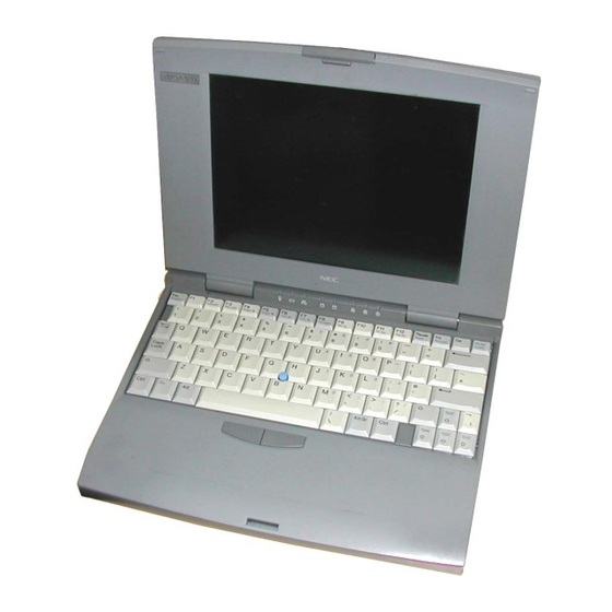
- Page 8 viii Contents Figures Figure Title Page Versa S Components ..................1-1 Versa S Series (Rear View) ................1-2 LED Status Bar ..................... 1-3 Opening the LCD Panel ................. 2-1 Attaching the AC Adapter................2-2 Connecting the Diskette Drive ............... 2-2 Turning on the Versa S ..................
- Page 9 Contents 4-17 Locating the Hard Disk.................. 4-13 4-18 Removing the Screw..................4-14 4-19 Removing the Hard Disk................4-14 4-20 Installing the Hard Disk ................. 4-15 4-21 Positioning the Keyboard ................4-15 4-22 Inserting the Retainer..................4-16 Locating the CMOS Clear Switch ..............5-3 Removing the Battery Pack................
- Page 10 Versa S Series Interrupt-Level Assignments........... 1-10 Specifications....................1-11 Status of Devices in Auto Suspend Mode............3-8 Status of Devices in Power Saving Mode............3-8 NEC Service and Information Telephone Numbers ........5-1 Problems and Solutions.................. 5-5 Error Messages....................5-7 Beep Codes ....................5-8 Disassembly....................
- Page 11 Contents...
-
Page 12: Technical Information
Section 1 Technical Information The NEC Versa™ S series sub-notebooks integrate Intel's SL Enhanced 486 microproces- sor. The systems offer a unique transportable unit in the following models: Versa S/50C 486DX2-50 CPU, thin-film-transistor (TFT) color LCD, 4-MB standard RAM, 8 KB cache RAM, 128-KB ROM, 260-MB hard disk... -
Page 13: Hardware Overview
Technical Information HARDWARE OVERVIEW The base unit includes a monochrome or color LCD panel, a 210- or 260-MB hard disk, an external 1.44-MB diskette drive, a battery pack, and a PS/2 compatible 80-key keyboard. A 81-key keyboard is used for U.K. and Germany. One memory card slot is available for the addition of a 4- or 8-MB memory card. -
Page 14: Keyboard
Technical Information Power-saving features for controlling the LCD's backlighting include the ROM-based hot key Fn F5, Fn F6, and Auto Setup power management settings. See Section 2, Setup and Operation, for information on using these settings. In addition, the automatic LCD status sense feature conserves the backlight. -
Page 15: Battery
Technical Information Power LED — lights yellow or green. When steady green, the computer is running on AC power. When steady yellow, the computer is running on battery power and battery power is sufficient. When blinking yellow, the computer is running on battery power and battery power is low. -
Page 16: System Board
Technical Information System Board The system board is inside the base unit. It contains system components including the CPU, system memory, and I/O subsystems. Refer to Table Section 1-1 for a summary of the chipsets supported by the Versa S. For a list of system board connector descriptions, see Appendix A. -
Page 17: Video Controller
Technical Information The Versa S supports system and video BIOS shadowing. When shadowing is enabled (de- fault settings), the BIOS is copied from ROM to RAM which speeds up system perform- ance. These settings can be changed in the SCU (see Section 2, Setup and Operation). Table Section 1-2 shows the system's memory map. -
Page 18: Input/Output Controller
Technical Information 640 x 480 8 x 16 80 x 30 256/256 25.0 31.5 60.0 NOTE: * External display only. Input/Output Controller The FDC37C665 input/output (I/O) controller provides the following interfaces: RS-232C serial port parallel (printer) port diskette drive IDE hard disk. The user selects between three parallel interface modes using Auto Setup. -
Page 19: Keyboard Controller
Technical Information *Default Keyboard Controller The keyboard controller (80C51SL) supports a PS/2-style keyboard, mouse and security features such as keyboard hot keys and password. Refer to Appendix A for keyboard inter- face connector pin assignments. The input clock cycle is 12 MHz. Data transmits between the controller and the keyboard through a bidirectional serial interface. -
Page 20: Interrupt Controller
Technical Information Table Section 1-6 Versa S I/O Address Map Address (Hex) I/O Device Name NMI Status NMI Mask 070-076 Real-time Clock 081H-083H DMA Page Register 087H DMA Page Register 089H-08BH DMA Page Register 08FH DMA Page Register 092H Port 92 0C0H-0CEH DMA Channel 0D0H-0DEH... -
Page 21: Power Management Overview
1-10 Technical Information Table Section 1-7 Versa S Series Interrupt-Level Assignments Controller Master/Slave Priority Name Device Master IRQ00 Counter/Timer 1 Master IRQ01 Keyboard Master IRQ02 Cascade for 8 to 15 Slave IRQ08 Real-time Clock Slave IRQ09 Slave IRQ10 Reserved Slave IRQ11 Reserved (PCMCIA) Slave... -
Page 22: Specifications
Technical Information 1-11 SPECIFICATIONS Table Section 1-8 provides a complete list of Versa E series system specifications. Table Section 1-8 Specifications Item Specification Chassis Size Width: 10.76 in. (276 mm) Depth: 8.26 inches (212 mm) Height: — Versa S/50C, S/33C: 1.63 in. - Page 23 1-12 Technical Information Table Section 1-8 Specifications Item Specification System Board Flash ROM 128 KB: 28F010 System BIOS: 64 KB Video BIOS: 32 KB Power Management: 32 KB I/O Interface Connectors 6-pin PS/2 External Keyboard/mouse Connector 9-pin Serial Connector 15-pin VGA Connector 25-pin Parallel Connector 3-pin DC-In Power Connector 72-pin Internal Memory Connector...
- Page 24 MS-DOS version 6.2 Windows version 3.1 APM drivers Mouse drivers Systemsoft CardSoft PCMCIA Auxiliary Windows Video Drivers (AWD) NEC Communications Assistant Versa S on-line help Windows and DOS on-line help Recommended Environment Operation Temperature: 41_ to 95_F (5_ to 35_C)
-
Page 25: Setup And Operation
Section 2 Setup and Operation This section provides setup and operation information for the Versa S (including cabling, power-on verification, and using the System Configuration Utility). UNPACKING THE SYSTEM Find an area away from devices that generate strong magnetic fields (electric motors, transformers, etc.). -
Page 26: Attaching The Ac Adapter
Setup and Operation Connect one end of the AC power cable to the AC adapter and the other end to a properly grounded wall outlet. The LED on the AC adapter and the Charge LED on the system lights. Power Port Adapter Power... -
Page 27: Replacing A Battery Pack
Setup and Operation Press the power button to turn on the system. NOTE: If operating on DC power, verify that the system has a charged battery pack installed. Power Button Figure Section 2-4 Turning on the Versa S Replacing a Battery Pack Follow these instructions to replace a battery pack. -
Page 28: Locating The Tabs And Grooves
Setup and Operation Locate the tabs on the end of the new battery pack. Fit the tabs into the grooves inside the compartment. Battery Battery Pack Pack Tabs Grooves Figure Section 2-6 Locating the Tabs and Grooves Lower the battery pack into the compartment. Press it down until the battery pack latch clicks and locks the battery in place. -
Page 29: Operating Controls
Setup and Operation OPERATING CONTROLS The following section describes system controls. Refer to Figure Section 2-8 to locate sys- tem controls and buttons. LED Status Keyboard Reset Button Fn Key Figure Section 2-8 Control and Button Locations LED Status Bar The LED status bar contains eight light emitting diodes (LEDs) that light or blink to show the status of Versa S components. - Page 30 Setup and Operation Power LED — lights yellow or green. When steady green, the computer is running on AC power. When steady yellow, the computer is running on battery power and battery power is sufficient. When blinking yellow, the computer is running on battery power and battery power is low.
-
Page 31: Surepoint And Selection Buttons
Setup and Operation SurePoint and Selection Buttons A pointing device that performs the functions of a mouse is located between the G, H, and B keys. To move the cursor on the screen in a specific direction, press against the SurePoint in that direction. -
Page 32: Reset Button
Setup and Operation n Fn-F5 — decreases the display brightness. NOTE: For longer battery power, decrease the brightness. n Fn-F6 — increases the display contrast. n Fn-F7 — decreases the display contrast. n Fn-F8 — accesses Power Management setup. n Fn-F9 —... -
Page 33: System Configuration Utility
Setup and Operation SYSTEM CONFIGURATION UTILITY The system uses the System Configuration Utility (SCU) to store information about the Versa S hardware and software. Use the SCU to perform the following functions: set date and time change CPU speed set a password activate power management features update system hardware changes. -
Page 34: Using The Scu
2-10 Setup and Operation The next three blocks show system settings. The Memory block displays system memory information. The Peripherals block shows settings for system peripherals. The Drives block specifies the diskette drive and hard disk installed. The bottom line of the screen shows what key functions are available at that screen level and what they do. - Page 35 Setup and Operation 2-11 COM Port A — Set the Serial Port I/O Address for COM Port A. COM1 (3F8h) – default setting COM2 (2F8h) COM3 (3E8h) COM4 (2E8h) Disable SurePoint — Enables or disables the SurePoint pointer. Enable – default setting Disable LPT Port Address —...
-
Page 36: Preferences
2-12 Setup and Operation Video Display — Set the video display type. Choose from the following selections if connecting an external monitor. VGA – default setting CGA80 Column CGA40 Column Monochrome Preferences Options available under the Preferences menu are described next. Quick Boot —... - Page 37 When the password entry is verified, SCU Password is enabled. No one will be able to use the SCU without first entering the SCU password. If the password is forgotten, call the NEC Technical Support number listed in Chapter 5.
-
Page 38: Vga
2-14 Setup and Operation First Boot — Select the drive that the system first looks for the operating system at system startup. Drive A – default setting PCMCIA Card Drive C VGA submenu option is described next. Display Mode — Select and activate the display mode. To use an external moni- tor with the Versa S, select "Both."... -
Page 39: Exit
Setup and Operation 2-15 Diskette Drive — 1.44 MB; diskette drive Hard Disk — Auto Video Display — VGA display Defaults set for the Preferences menu are as follows. Quick Boot — Disabled; performs memory test at start-up Num Lock — Disabled; off at start-up Boot Speed —... - Page 40 2-16 Setup and Operation If any of the SCU settings were changed, the following screen message appears. Do you wish to save your changes? ESC to exit – Enter to save and exit Any other key to continue is pressed, the system does not save any changes and exits the SCU. The system does not reboot.
-
Page 41: Power Management
Section 3 Power Management Power Management is a set of power-saving features built into the Versa S. These features conserve energy, maximize the life of the battery pack and LCD backlight, and protect against data loss due to low battery power. Versa S has two programs that work together to provide power management capabilities. -
Page 42: Power Management Menu
Power Management A screen similar to the following appears. Controls System Device Defaults Exit SystemSoft MAXIMIZER(TM) for 80486/86C268 Version 0.3(2305-02] Copyright 1990-1994 SystemSoft Corp. All Rights Reserved Controls System Options Power Savings: Always CPU Idle: Disable LCD Brightness Control: Full Global Standby: Disable Battery Low:... -
Page 43: Menu Options
Power Management Menu Options Descriptions of the menu bar selections and options follow. Controls Use the Controls menu to enable and disable the following features. Power Saving — This option specifies when power saving features are enabled. Select from the following choices. Always –... -
Page 44: System Options
Power Management System Options System Options menu specifies how long the system is inactive before initiating power- saving features and going into Suspend mode. Use the System Options menu to enable and disable the following features. CPU Idle — Set how long the system is idle before slowing the rate of the CPU speed. -
Page 45: Device Setup
Power Management 60 Mine Disable Video Monitoring — Specify whether Power Management monitors video activ- ity as it relates to going into Suspend mode. Disabling video monitoring is useful for applications that have something happening on the screen constantly. For ex- ample, a changing clock on the screen can keep the system from initiating power saving features even though the system is not in use. -
Page 46: Default Setup
Power Management 6 Min 8 Min 12 Min 16 Min Always On Default Setup Highlight Default Setup and press Enter to reset Power Management options to their de- fault settings. Exit Highlight Exit to exit the Power Management Utility screen. Press Enter . -
Page 47: Hardware Power Management
Power Management Hardware Power Management Specific hardware power management features include the following. Clock stretching — APM reduces the CPU speed without adding a wait state when a 0.5-cycle wait state is needed in case of DRAM access. Quiet bus — APM inhibits all signals in the AT Bus except the AT bus cycle. This function saves energy by reducing the number of unnecessary charges and dis- charges. -
Page 48: Device Status
Power Management Device Status The following table shows the status of system devices in Auto Suspend mode. Table Section 3-1 Status of Devices in Auto Suspend Mode Device Status PT86C368 Suspend Main/expansion memory Slow refresh 82C206 Active 32-KHz Oscillator Active 80C51SL Standby VGA Controller... -
Page 49: Extending Battery Life
Power Management Table Section 3-2 Status of Devices in Power Saving Mode Global Device Standby Standby Suspend External keyboard Active Active Cirrus VGA Standby Slow Refresh LCD (Display and Backlight) SurePoint PS/2-Style Mouse Diskette Drive Standby Hard Disk Standby Serial Port Buffer EXTENDING BATTERY LIFE Use the following guidelines to reduce power consumption and maximize battery life. -
Page 50: Options
Hard disk. NOTE: Some options described here may not be available outside of the U.S. Contact an authorized NEC dealer for specific information. PCMCIA CARDS The Versa S has two PCMCIA card slots for attaching options like a fax/modem, Local Area Network (LAN) card, additional memory, and extra hard disk storage. -
Page 51: Modem Card Connection
Options The PCMCIA slots are located on the left side of the Versa S. Slot 0 is the bottom slot; slot 1 is the top slot. PCMCIA Card Slot Figure Section 4-1 PCMCIA Card Slots Modem Card Connection A telephone cable with modular (RJ11) connectors on both ends is required to connect a modem card to a telephone system. -
Page 52: Installing The Modem Card
Options Follow these steps to connect the system to a phone line. Install the PCMCIA modem card in one of the slots in the Versa S. (See the Versa Series PCMCIA User’s Guide for details about installation.) PCMCIA Card PCMCIA Card Slot Figure Section 4-2 Installing the Modem Card Connect the modem adapter to the modem card. -
Page 53: Telephone Line Connection
Options Proceed as follows: To connect the modem directly to a wall outlet, plug the other end of the phone cable into a telephone jack in the wall. Attaching the modem is complete. To connect the modem and telephone to the same wall jack, go to step 5. (To connect both the modem and telephone, a dual-RJ11 connector is needed.) Telephone Jack... -
Page 54: External Devices
Options Dual RJ11 Connector Figure Section 4-5 Modem and Telephone Connection EXTERNAL DEVICES This section provides installation procedures for connecting external devices to the Versa S. Before connecting the device, set it up using the instructions that come with the device. Parallel Devices To install a printer or other parallel device, a cable with a 25-pin male connector is required. -
Page 55: Serial Devices
Options Serial Devices To install a serial device, like a printer or an external modem, a cable with a 9-pin female connector for the system is required. Follow these steps to attach a serial device to the Versa S. Check that power to both Versa S and device is off. Open the port cover on the back of the system and locate the serial port. -
Page 56: Mouse
Options Connect the keyboard cable connector to the port. Keyboard Connector Keyboard/ Mouse Port Figure Section 4-8 Attaching the External Keyboard NOTE: The Fn-Esc or Fn-F9 key combination cannot be used from the external keyboard. Mouse The software needed to recognize the external mouse in Windows and DOS programs is al- ready installed in the system. -
Page 57: Monitor
Options Connect the mouse cable connector to the port. Mouse Connector Keyboard/ Mouse Port Figure Section 4-9 Connecting the Mouse Turn on the system and start the SCU. Under the Standard menu, locate the SurePoint option and disable it. NOTE: The SurePoint or its selection buttons cannot be used when attaching an external mouse. -
Page 58: Internal Upgrades
Options Slide the cover latch down and open the port cover on the back of the Versa S. Connect the 15-pin cable connector to the monitor port on the Versa S. Attach and secure the connection with the screws provided. Screws VGA Port Monitor Cable... -
Page 59: Moving The Keyboard
Section 4 Moving the Keyboard Follow these steps to move the keyboard out of the way before installing memory or re- placing the hard disk. Unplug the Versa S system and any peripheral devices connected to it. Turn off system power. NOTE: Do not leave the system in Suspend or Standby mode when installing internal options. -
Page 60: Lifting The Keyboard
4-10 Options Figure Section 4-2 Removing the Retainer Move the keyboard out of the way as follows: Gently lift the back of the keyboard up no more that 1.5 inches. Pull the keyboard back slightly to release the front tabs from under the chassis. Keyboard Figure Section 4-3 Lifting the Keyboard Once the keyboard clears the chassis, gently turn the keyboard over, moving... -
Page 61: Upgrading Memory
Options 4-11 Upgrading Memory The Versa S comes with 4 megabytes (MB) of random access memory (RAM) installed on the system board. Memory can be increased up to a maximum of 12 MB, by installing one of the following memory modules. 4-MB memory module 8-MB memory module. -
Page 62: Upgrading The Hard Disk
4-12 Options Press the memory module gently to ensure a secure connection. Figure Section 4-6 Installing the Module If there is nothing else to be installed, go to “Replacing the Keyboard” to continue with the upgrade. Upgrading the Hard Disk Upgrade the hard disk as follows: Move the keyboard out of the way following the instructions in “Moving the Key- board.”... -
Page 63: Removing The Screw
Options 4-13 Locate and remove the screw that secures the protective shield and the drive. CAUTION: Do not use a magnetic screwdriver when removing the screw. Doing so can erase the data on the hard disk. Shield Screw Figure Section 4-8 Removing the Screw Lift the shield out of the system. -
Page 64: Replacing The Keyboard
4-14 Options Firmly press the drive towards the connectors until the attachment is secure. Hard Disk Figure Section 4-10 Installing the Hard Disk Lower the protective shield over the hard disk. Replace the screw that secures the drive and shield. CAUTION: Do not use a magnetic screwdriver to replace the screw. -
Page 65: Running Setup
Options 4-15 Lower the keyboard back into position. CAUTION: Be sure to tuck the keyboard cables under the keyboard. Re-insert the plastic retainer as follows: Locate the tabs on the retainer. Align the tabs with the grooves in the system. Fit the tabs into the grooves. -
Page 66: Hard Disk
4-16 Options Press Fn-F9 to save the amount of memory. Once the information is saved, the system automatically recognizes the additional memory. Hard Disk If replacing the hard disk, follow these steps. Press to start the SCU. Select Standard, then HDD, then Ctrl-Alt-S Fn-F9 Auto to read the new hard disk parameters. -
Page 67: Troubleshooting And Repair
Section 5 Troubleshooting and Repair This section provides information on maintaining, troubleshooting, and repairing the Versa S series sub-notebooks. NEC service and information telephone numbers are listed in Table Section 5-1. Table Section 5-1 NEC Service and Information Telephone Numbers... -
Page 68: Maintenance
Troubleshooting and Repair MAINTENANCE This subsection contains general information for cleaning and checking the system unit, keyboard, and LCD. The system unit, keyboard, and LCD require cleaning and checking at least once a year, and more often if operating in a dusty environment. No other scheduled maintenance or lubrica- tion is required. -
Page 69: Cmos Clear Switch
Troubleshooting and Repair CMOS CLEAR SWITCH The CMOS clear switch deletes the system configuration information that was stored in CMOS memory by the SCU. Use this switch when a user forgets his password. Activating the switch will clear the old password, allowing him to set a new one. After activating the switch, the SCU must be run to reenter the sytem configuration information (date, time, hard disk type, and so on). -
Page 70: Troubleshooting
Troubleshooting and Repair Using a non-conductive tool, slide the switch toward the front of the unit, and then slide it back to its original position (toward the rear of the unit). Turn off the system power. Replace the keyboard (see “Replacing the Keyboard” in Section 4, Options). Run the SCU to reenter the system configuration information (see Section 2, Settup and Operation). - Page 71 Troubleshooting and Repair The following subsections provide corrective actions when the computer has an error con- dition. Refer to the appropriate section and Table Section 5-2 to help isolate the problem. Also see Table Section 5-2 if an error occurs and the system does not display an error mes- sage or transmit a beep code.
-
Page 72: Error Messages
Troubleshooting and Repair Table Section 5-2 Problems and Solutions Problem Corrective Action Memory malfunction Reseat the memory card. Replace the memory card. Replace the system board. Keyboard or pointer malfunction Check that the keyboard cables are connected to the system board. Replace keyboard. - Page 73 Troubleshooting and Repair If either condition exists, press Ctrl-Alt-S and run the SCU. Check the last settings to see if they are still active or select Defaults to resolve configuration problems quickly. If the problem persists, see Table Section 5-2 for further assistance. Other error messages are provided in Table Section 5-3.
-
Page 74: Beep Codes
Troubleshooting and Repair Beep Codes When the system detects an error and cannot display an error message because of the hard- ware fault, the system indicates the error by beeping. One beep indicates that the computer has completed its power-on self-test. If intermittent beeping occurs, power off the computer and try again. -
Page 75: Removing The Battery Pack
Troubleshooting and Repair Table Section 5-5 Disassembly Sequence Part See Page System cover and LCD assembly 5-15 CMOS or bridge battery 5-17 Inverter circuit board 5-18 System board 5-19 LED circuit board 5-20 LCD cover 5-21 Separating the LCD assembly from 5-22 the system cover All other system components must be removed at the factory (depot). -
Page 76: Removing The Keyboard
5-10 Troubleshooting and Repair At the bottom of the system, slide the release latch and remove the battery pack. Battery Battery Pack Release Latch Figure Section 5-2 Removing the Battery Pack Removing the Keyboard Follow these steps to remove the keyboard. NOTE: Do not leave the system in Suspend or Standby mode when installing internal options. -
Page 77: Removing The Retainer
Troubleshooting and Repair 5-11 Flip the retainer up to remove it. Put it in a safe place. The keyboard springs up a ways when the retainer is removed. Retainer Figure Section 5-4 Removing the Retainer Move the keyboard out of the way as follows: Gently lift the back of the keyboard up no more that 1.5 inches. -
Page 78: Leaning The Keyboard Against The Lcd
5-12 Troubleshooting and Repair Once the keyboard clears the chassis, gently turn the keyboard over, moving the keys towards the LCD panel. Rest the keyboard on the LCD panel. Keyboard (bottom) Figure Section 5-6 Leaning the Keyboard Against the LCD Using a non-conductive tool, disconnect the three keyboard cables from the sys- tem board. -
Page 79: Removing The Memory Module
Troubleshooting and Repair 5-13 Removing the Memory Module Follow these steps to remove the memory module. Turn off system power. Unplug the Versa S and any peripheral devices connected to it. Move the keyboard out of the way (see the instructions in the preceding section). Locate the memory module on the system board. -
Page 80: Removing The Hard Disk
5-14 Troubleshooting and Repair Removing the Hard Disk Follow these steps to remove the hard disk. Turn off system power. Unplug the Versa S and any peripheral devices connected to it. Move the keyboard out of the way following the instructions in “Removing the Keyboard.”... -
Page 81: Removing The System Cover And Lcd Assembly
Troubleshooting and Repair 5-15 Slide the shield to the right away from the system board. Lift the shield out of the system. Disconnect the hard disk from its connectors and slide it out of the system. Hard Disk Figure Section 5-12 Removing the Hard Disk Removing the System Cover and LCD Assembly Follow these steps to remove the system cover and LCD assembly from the system chassis. - Page 82 5-16 Troubleshooting and Repair Turn the system over. Make sure the system is protected from any hard surfaces that could scratch it. Locate the three rubber plugs that conceal the bottom cover screws. Using a small flat-tip screwdriver or other sharp object, pry out the rubber plugs.
-
Page 83: Removing System Cover Screws (Top)
Section 5 Turn the system over. Make sure the system is protected from any hard surfaces that could scratch it. Locate the three rubber plugs that conceal the bottom cover screws. Using a small flat-tip screwdriver or other sharp object, pry out the rubber plugs. Remove the three screws securing the system cover to the system chassis. -
Page 84: Removing The Cmos Or Bridge Battery
5-16 Troubleshooting and Repair Remove the system cover and LCD assembly as follows: Open the PCMCIA cover and lightly lift up on the system cover, providing a small separation between the system cover and system chassis. CAUTION: The system cover is fragile. Start at the front of the system when removing the system cover from the chassis. -
Page 85: Removing The Cmos And Bridge Batteries
Troubleshooting and Repair 5-17 Disconnect the battery cable from the system board and remove the battery. CMOS Bridge Battery Battery Figure Section 5-4 Removing the CMOS and Bridge Batteries Removing the Inverter Circuit Board Follow these steps to remove the inverter circuit board. Turn off system power. -
Page 86: Removing The System Board
5-18 Troubleshooting and Repair Removing the System Board Follow these steps to remove the system board. Turn off system power. Unplug the Versa S and any peripheral devices connected to it. Remove the following items using the procedures provided earlier in this section: keyboard hard disk system cover and LCD assembly... -
Page 87: Removing The Led Circuit Board
Troubleshooting and Repair 5-19 Removing the LED Circuit Board Follow these steps to remove the LED circuit board. Turn off system power. Unplug the Versa S and any peripheral devices connected to it. Remove the following items using the procedures provided earlier in this section: keyboard hard disk system cover and LCD assembly. -
Page 88: Removing The Lcd Cover
5-20 Troubleshooting and Repair Removing the LCD Cover Follow these steps to remove the LCD cover. Turn off system power. Unplug the Versa S and any peripheral devices connected to it. Remove the following items using the procedures provided earlier in this section: keyboard hard disk system cover and LCD assembly. -
Page 89: Separating The Lcd Assembly From The System Cover
Troubleshooting and Repair 5-21 Separating the LCD Assembly from the System Cover Follow these steps to remove the LCD assembly. Turn off system power. Unplug the Versa S and any peripheral devices connected to it. Remove the following items using the procedures provided earlier in this section: keyboard hard disk system cover and LCD assembly... -
Page 90: Illustrated Parts Breakdown
Troubleshooting and Repair ILLUSTRATED PARTS BREAKDOWN This subsection contains the illustrated parts breakdown (IPB) and NEC part numbers for the Versa S. Table Section 5-1 lists the field-replaceable parts for the Versa S, Table Sec- tion 5-2 lists the documentation available for the Versa S, and Figure Section 5-10 shows the IPB. - Page 91 Troubleshooting and Repair 5-23 Table Section 5-1 Versa S Field-Replaceable Parts List Item Description Part Number Keyboard 808-873936-500A Hard Disk Bracket (Shield) 136-613569-001A Hard Disk, 200 MB 136-792874-002A Hard Disk, 260 MB 136-792874-003A Hard Disk Ground Holder 136-612447-A AC Cable 808-873936-609A Battery Pack 808-873936-600A...
-
Page 92: Versa S Illustrated Parts Breakdown
5-24 Troubleshooting and Repair Figure Section 5-10 Versa S Illustrated Parts Breakdown ____________ This data was prepared June 1994. For an up-to-date listing of spare parts, please call Fast-Facts (800) 366-0476 and order document umber 42180975. - Page 93 Index CMOS clear, 5-3 Accessing Power Management, 3-1 COM port assignments, 2-11 Connector Accessing the SCU, 2-9 DC power, A-4 Adding options, 4-1 diskette drive, A-4 Addresses hard disk, A-5 parallel port, 1-7 keyboard/mouse, A-3 serial port, 1-7 parallel interface, A-2 Advanced Power Management (APM) device status, 3-8 RS-232C serial interface, A-1...
- Page 94 Index-2 system board, 5-19 Installing system cover and LCD assembly, 5-15 external devices, 4-5–4-9 Diskette drive connector, A-4 external keyboard, 4-6 Diskette drive type settings, 2-11 hard disk, 4-13–4-15 Display internal devices, 4-9 external, 1-6 memory, 4-12–4-13 mode, 2-14 monitor, 4-8 type, 2-12 mouse, 4-7 moving the keyboard, 4-10–4-11...
- Page 95 Index-3 Dualscan Super-Twisted Nematic, 1-2 monochrome, 1-2, 1-6 Operating Controls status sense feature, 1-3 Fn key, 2-7 thin-film transistor, 1-2 Options video modes, 1-6 external devices, 4-5–4-9 LCD assembly external keyboard, 4-6 removing, 5-15, 5-22 hard disk upgrade, 4-13–4-15 LCD cover internal upgrades, 4-9 removing, 5-21 memory upgrade, 4-12–4-13...
- Page 96 Index-4 exiting, 3-6 Num Lock, 2-12 extending battery life, 3-9 password, 2-13 Fn-F8, 3-1 quick boot, 2-12 global standby, 3-4 saving changes, 2-15 hard disk, 3-5 setting the date, 2-10 making selections, 3-2 setting the time, 2-10 menu options, 3-3 SurePoint, 2-11 modem-ring resume, 3-3 typematic delay, 2-13...
- Page 97 Index-5 beep codes, 5-8 CMOS clear switch, 5-3 diagnosing and solving problems, 5-4 error messages, 2-8, 5-6 problem checklist, 5-4 Typematic delay, 2-13 Typematic rate, 2-12 Unidirectional mode, 1-7 Unpacking, 2-1 Upgrades 260-MB hard disk, 1-1 memory, 1-1 Upgrading memory, 4-12–4-13 Upgrading the hard disk, 4-13–4-15 Versa SurePoint, 1-3 VGA interface connector, A-3...
- Page 98 Index-6...
- Page 99 (For United States Use Only) FEDERAL COMMUNICATIONS COMMISSION RADIO FREQUENCY INTERFERENCE STATEMENT WARNING: Changes or modifications to this unit not expressly approved by the party responsible for compliance could void the user’s authority to operate the equipment. NOTE: This equipment has been tested and found to comply with the limits for a Class B digital device, pursuant to Part 15 of the FCC Rules.
- Page 100 BATTERY REPLACEMENT A lithium battery in your computer maintains system configuration information. In the event that the battery fails to maintain system configuration information, NEC recommends that you replace the battery. See Chapter 5 for battery replacement information. WARNING: There is a danger of explosion if the battery is incorrectly replaced. Replace only with the same or equivalent type recommended by the manufacturer.