Advertisement
Introduction
Before you start
It is recommended to check behringer.com for firmware updates, as new features and bug fixes will be released regularly. Please refer to Chapter "Firmware updates" in this QSG for details about the update process.
Our development team is eager to read your feedback on ideas.behringer.com and surprise you with new improvements and features.
Source and Channel – a new routing approach
WING has introduced a new way of labeling signal sources with names, icons and color together with their physical parameters. WING Sources can be fed into one or several channels for signal processing or routing to buses or main buses. They can also be patched directly to any physical output when no processing is desired, such as in recording setups, or when sharing audio with another console for independent mixes.
Sources/channels/buses and outputs
External Sources
Any audio input into the console is called a Source. An input can be an analog signal via the XLR or ¼" TRS connectors on the rear panel, or digital signals via StageConnect, USB, AES50, installed expansion cards, etc.
WING Sources include the following information:
- Identifying characteristics like name, color, icon, and tags
- Physical characteristics such as gain, mute, phase inversion and phantom power
- Mono/stereo/mid-side configuration. All 40 channels on the console can process either mono or stereo signals. Analog and digital stereo signals can be fed into a single channel in the console. See Chapter "ROUTING" for more information.
Internal Sources
WING also features User Signals, User Patches and the Oscillator that can be used just as any external Source, but they are in fact signals taken from other places in the console's audio engine.
2 Oscillators
There are two independent mono test tone generators that can be configured for sinewave, pink noise or white noise output. They can be routed to any channel or output.
24 User Signals
These are signals derived from any of the 40 input channels, 8 aux input channels, 16 buses, 8 matrices or 4 main buses. They can be tapped from the respective channel's pre- or post-fader tap points, and carry either the left or right channel, or a sum of both.
24 User Patches
These are also signals taken directly from any of the external source signals. User Patches allow you to create stereo combinations of raw input signals that don't belong to the same Source Group. Possible applications are:
- Combining two signals from different Source Group interfaces into a stereo or mid-side configuration
- Combining non-adjacent signals into a stereo or mid-side configuration
- Apply different gain to each channel of a stereo or mid-side configuration
- Apply phantom power to only one channel of a stereo or mid-side configuration
48 Mono/Stereo Input Channels
The channels on WING COMPACT allow for extremely powerful and flexible processing of the Source audio, before mixing them into buses or mains. Each Input Channel can accommodate a Main or an Alternative Source. They can adopt the Source's customization properties and automatically use the Source's mono or stereo configuration.
Unlike with other consoles, there is no need for linking two mono channels into a stereo pair — all channels can process mono or stereo signals.
Channel audio can then be sent to buses or mains for mixing, or it can be tapped individually and routed to the outputs directly.
16 Stereo Buses and 4 Stereo Main Buses
The 16 buses are typically used for effects processing through sends, monitor mixes and applying group processing to sub mixes. Buses can be fed into the 4 main buses, to the first 8 buses or to the 8 matrices. The 4 main buses can only be sent to Matrices or Output destinations.
8 Matrix Buses
Matrix buses have full processing and can be sent to any Output destinations. They are often used for sub- or zone mixes that need processing or time alignment.
Matrix buses can be driven by aux or main buses. They also feature two additional Direct Inputs that can be taken from any of the Input Channels, tapped pre- or post-fader.
Matrix buses can be used for creating so-called Mix-Minus buses, by phase inverting i.e. subtracting the Direct Inputs from the mix. This is often applied in broadcast situations, when a moderator should hear everything but his own voice in the mix. They can also be fed back into input channels.
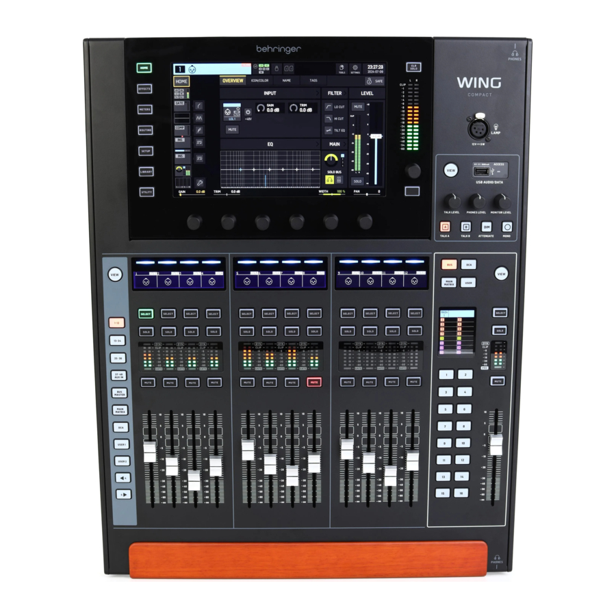
Hardware Descriptions
VIEW buttons

Pressing one of the VIEW buttons will switch the Main Display to a dedicated screen for the section the button was pressed on. The Main Display will often have additional parameters, options or information that is not accessible from the top panel alone.
While active, each VIEW button will light green.
Some VIEW buttons support a press-and-hold function that accesses an additional setup page. For example, pressing and holding any of the fader bank VIEW buttons opens the edit screen where channels and buses can be rearranged on the fader layers.
Lamp socket
The lamp socket above the monitoring section accepts a standard 12 V DC light.

Monitoring/Talkback/USB
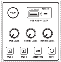
A USB type-A connector allows a flash drive to be plugged directly into the console for saving or loading data. This allows you to back up your show files or load your usual setup on a rented WING console.
This USB connection allows recording and playback of two- or four-channel-WAV audio files. The port can also charge a portable device such as a phone or tablet. Flash drives connected to the USB port can be disconnected whenever the ACCESS light has turned off.
Dedicated knobs control the headphone and monitor output level of the buses MONITOR A and MONITOR B, respectively, found in the source group "Monitor" in the ROUTING screen. Both stereo buses can be routed to any physical output.
Engaging the DIM button reduces the monitor volume temporarily. The MONO button sums the monitor signal to mono. Holding the DIM button mutes the monitor. Holding the MONO button swaps left and right monitor signals. In order to use the headphone connectors on the console the monitor signals must be routed to the corresponding outputs (these are indicated with a headphone symbol on the output routing page, i.e. Aux 7/8 for the WING COMPACT console).
The talkback mic level can be adjusted via the TALK LEVEL knob and TALK A and B buttons send the talkback signal to different destinations. Either Channel 40 or Aux 8 can be used as processing channel for the talkback signal. Processing can be applied as needed. Any input can be assigned to the selected talkback channel.
Press the VIEW button to control the monitor settings, adjust the amount of Dim attenuation, setup the routing for the talkback mic, and other parameters.
Fader Sections
The WING COMPACT has two fader sections: the input channels section and the main fader section.

Input Channels
The 12 faders to the left side of the console can accommodate multiple sources: input channels, aux channels, buses, mains, matrices, DCAs and user-customizable banks or layers. Note that all banks can be customized. USER1 and USER2 are empty by default.
Selecting different fader banks with the layer/bank buttons on the left grey area will bring a new set of channels to the input channels fader section. If a particular bank exceeds the amount of available physical faders in the section, the shift arrows will scroll in blocks of four (or 12 or 8 depending on setup configuration) channels to access the remaining ones.
To access the fader bank configuration, press and hold the VIEW button. To assign channels to the selected bank, drag and drop them from the CHANNELS, BUS/MAIN and DCA tabs to the bottom of the screen.
Main fader
WING Compact's main fader section is especially designed for applications where quick adjustments to bus sends are vital. 16 hot keys automatically activate sends on fader mode to the corresponding bus. For instance, when pressing the "1" button, each channel's fader controls the send level to bus 1.
On top of the 16 buses, this section also controls the 4 main buses, 8 matrices, 16 DCAs and user-customizable banks.
The screen shows what is currently controlled by the main fader and each of the 1-16 buttons.
By default, when none of the 1-16 buttons are highlighted, the main fader controls the MAIN1 level, independent of the BUS MASTER, DCA, MAIN/MATRIX and USER buttons state. This can be changed on the SETUP>SURFACE menu.
- MAIN/MATRIX: buttons 1-4 control the sends to the main buses 1 to 4. "Sends on Faders" is activated on the input channels section when pressing one of the 1-4 buttons. The sends from specific channels to the selected bus are activated by unmuting the respective channel. The corresponding fader controls the send level.
Holding down one of the 1-4 buttons activates "spill" mode on the input channels section, so that the channels currently being sent to the selected main bus are shown on the input channel faders.
Buttons 9-16 control the sends to matrices 1-8. Pressing one of the buttons 9-16 activates spill mode for the desired matrix. Holding down the button activates "sends on fader mode" for the desired matrix. Note that only buses and main buses can be sent to matrices.
Note that the send level to the main buses and the channel fader are independent. When none of the 1-16 buttons are lit, each fader controls the corresponding channel's level. When one of the 1-16 buttons are lit, each fader controls the corresponding send level to the selected main bus or matrix.
To change whether sends on fader or spill mode will be activated when pressing the 1-16 buttons once and when holding them down, go to:
SETUP>SURFACE>MAIN SPILL ON/OFF
SETUP>SURFACE>MATRIX SPILL ON/OFF
- BUS MASTER: buttons 1-16 control each of the 16 buses. Pressing a button once activates sends on fader mode for the corresponding bus. Holding down the button activates spill mode for the same bus. To change how each mode is activated, go to:
SETUP>SURFACE>BUS SPILL ON/OFF - DCA: buttons 1-16 activate spill mode for each of the corresponding DCAs. Channels can be assigned to a DCA by pressing the DCA button on the master section, then pressing one of the 1-16 buttons, holding down the SELECT button on the master section, navigating through the desired fader banks on the input channels and pressing SELECT on the desired channels. Alternatively, a channel can be assigned to a DCA through HOME>TAGS.
- USER: up to 20 different controls can be assigned to the 1-16 buttons on the master section. To do so, hold down the VIEW button. 5 layers of 4 buttons each are available to the left of the screen. The layers can be navigated with the arrows on the top left-hand corner. Each layer is assigned to the following buttons:
- LAYER 1: USER 1-4
- LAYER 2: USER 5-8
- LAYER 3: USER 9-12
- LAYER 4: USER 13-16
- LAYER 5: MAIN/MATRIX 5-8
Scribble strips/meters/select

Each fader strip has a mini display screen called a scribble strip. This will indicate information about the current channel/bus number, name and an icon to quickly identify which channel is currently controlled by the fader and associated buttons.
A color bar above the scribble strip allows quick visual identification of groups of related channels. Scribble strip details and color bar options can be edited on the HOME screen of the selected channel, in the ICON/COLOR tab. The channel signal source can also be indicated on the scribble strip when enabled (SETUP>SURFACE>SHOW SOURCE ON SCRIBBLE).
Pressing the SELECT button directs the control focus of the Main Display to that channel or bus. Only one SELECT button can be active at any time. Pressing SELECT again (when the channel is already selected) will return the display to the channel home or insert page of a bus (SETUP>SURFACE>SEL DBL CLICK) to quickly adjust channel or insert/effect parameters.
The SOLO button will isolate that channel for monitoring, along with any other channels or buses that are soloed. The MUTE button mutes the channel currently assigned to that strip.
Stereo level meters provide input level information, from -60 dB to Clip. The DYNAMICS LED will light whenever the dynamic processor's threshold is exceeded, triggering the compressor/expander. Likewise, the GATE LED will light whenever the input signal falls below the noise gate's threshold.
Main Display

Most of WING's controls can be edited via the 10" touch screen Main Display. The seven buttons to the left of the display and the VIEW buttons located in each major section of the top panel allow access to different settings screens. An overview of each screen is presented in Chapter "Main Screens".
The six knobs below the display allow parameter adjustments of the items shown at the bottom of the current screen. These are touch sensitive knobs that will highlight elements on the screen as soon as the associated knob is touched. An additional seventh knob to the right of the display can be used for context-dependent control by first touching an item on the Main Display, allowing for finer adjustments compared to moving virtual knobs or faders. A multi-purpose button beneath the seventh knob performs similarly depending on the current screen. For example, it can be used as a tap tempo when editing delay effects.
The large stereo meter will either display the main bus or solo bus levels. The CLR SOLO button will release all channels and buses that are active in the solo bus.
Rear Panel
Analog I/O/MIDI and GPIO
The rear panel analog connections include 24 Midas PRO series microphone preamps with combo jack connectors and 8 XLR outputs.
5-pin MIDI IN and OUT jacks allow external MIDI control, and a ¼" TRS jack for two GPIOs allow basic input and output commands.

ETHERNET/AES50/Control/StageConnect

A pair of Ethernet ports allow a network to be set up via router for wired or wireless control using one of the control apps on a computer or mobile device.
The console also can be connected to a computer via the USB type B connector for the following uses:
- 48 input/48 output audio interface. The corresponding ASIO driver can be downloaded at behringer.com.
- MIDI DAW controller
- Firmware updates
- Data exchange
3 AES50 ports each provide up to 48 input and output channels to and from digital stage boxes, ensuring a high channel count and allowing patching to and from multiple locations. The WING is fully compatible with all X32 series mixers and stage boxes.
All AES50 connections between WING and stage boxes should have:
- Shielded CAT-5e cables
- Ethercon-terminated cable ends
- Maximum cable length of 80 meters
StageConnect transmits up to 32 digital audio input or output channels using a standard balanced XLR cable (110 Ω impedance DMX-cable recommended).
The interface supports different bus configurations of input and output channels and uses digital, uncompressed PCM audio at 44.1/48 kHz and 24-bit resolution. StageConnect was developed for flexible connections on stage or to a side rack, supporting a wide range of applications at sub-millisecond latency.
Stereo AES3 (AES/EBU) input and output connections can be made via XLR cables.
Expansion Slot
The WING console ships with the WING-LIVE card installed, which allows up to 64 channels of 48 kHz / 32-bit audio to be recorded onto a pair of SD or SDHC cards. Cards with other protocols such as Dante, MADI and SoundGrid can be installed in this slot.

Power

Connect the included IEC cable.
Main Screens
Most of the advanced editing and control is done on the Main Display. Screens can be navigated via the seven buttons to the left of the screen, or via VIEW buttons in each section of the top panel.
There are six screens accessible via the buttons next to the Main Display:
- HOME
- EFFECTS
- METERS
- ROUTING
- SETUP
- LIBRARY
Note that the UTILITY button does not have a specific screen related to it.
A status bar is displayed at the top of the screen to provide a quick reference for channel name, clock, and alerts. This also allows constant access to the SD card controls, setup menu, library functions and other tools.
HOME
HOME
The screen defaults to an overview of the selected channel. This screen allows adjustment of basic parameters like pan and level, but mostly provides a starting point to access important processing blocks like EQ and dynamics.

The processing sequence of the gate, dynamics, EQ, and insert sections, as well as the tap point for the signal sent to the 16 buses can be adjusted by clicking on the wrench icon on the bottom-left corner of the HOME screen and dragging the blocks.

INPUT
The INPUT screen appears second in the left-hand column. The primary and alternate Source that is assigned to the current channel is selected here. Signals can be configured as mono, stereo or mid side with the corresponding M, ST and M/S buttons.
The FILTER screen is also a part of this section, allowing low cut, high cut and advanced filtering options like tilt filter and all-pass filter for phase alignment.
Finally, the DELAY (POST) controls the delay applied to the channel output signal. This delay is necessary for the signals driving loudspeakers further away from the main PA, for instance.

GATE
The GATE screen appears third in the left-hand column. The block defaults to a simple noise gate with common parameters like threshold and ratio, though other processors can be loaded on the Gate Model menu. This block's name will change to reflect the chosen model.
EQ
block defaults to a 6-band fully parametric equalizer for input channels, and an 8-band fully parametric equalizer for buses. A variety of digital and emulations of analog EQ models can be selected from the EQ Model menu.
DYNAMICS
block offers a large selection of digital and emulations of analog compressors, expanders and limiters.
PRE FADER INSERT
Here internal or external effects from one of the 16 FX slots can be inserted into the channel. It can be positioned before or after the Gate, EQ and/or Dynamics blocks.
POST FADER INSERT
The second insert is fixed post-fader and post-processing. It can be used to add FX processing, or to control the channel level by one of 2 auto mixing groups that apply automatic gain-sharing across the assigned channels.
MAIN
The screen allows the send level to each of the four main buses to be adjusted along with the stereo width, pan and channel fader level.
BUS SENDS
The last screen in the left-hand column allows adjustment of send levels to all 16 buses. The tap point for each send can be set up using the dropdown menu on the top left-hand corner, or by clicking on the wrench icon on the HOME screen and moving the Tap. A three-band EQ is available for the signal sent from the tap point to the 16 buses.

The HOME screens have a similar appearance when a bus, main or matrix channel is selected, except no GATE block is available and only trim can be adjusted. On the INPUT screen, the bus send can be set to pre fader (according to the tap point setting) or post-fader if they will be used for monitoring or effects sends, or to subgroup if channels will be routed to the bus for common processing, prior to the main mix.
EFFECTS

The EFFECTS screen controls all aspects of the effect processors. Users can select from a large collection of virtual emulation of analog processors, configure routing, adjust parameters and monitor levels.
The eight PREMIUM FX slots can accommodate every device (FX1-8, STD and CH categories). The STANDARD FX slots can accommodate STD and CH effect categories. Note that the CH category contains four channel devices which integrate three effect devices in a single slot, and a mastering device that integrates four.
Up to 16 devices can be loaded onto the slots on the EFFECTS screen. These devices can then be loaded as insert points. The analog emulations and digital effects available on the GATE, COMP and INS sections of each channel strip are loaded directly on each channel and not on the 16 slots of the EFFECTS screen.
Effects are usually applied to channels in one of two ways: through bus sends or via insert points. Time-based effects like reverb and delay are usually set up via bus sends, whereas dynamic processing is usually set up via insert points.
Effects on bus sends
To set up an effect via a bus send, select the channel to which the effect will be added. In the BUS SEND section of the HOME screen, activate the desired send by unmuting the desired channel and adjusting the respective fader in the main display.
The insert point on the channel accommodating the bus is used to load the desired effect. Make sure this channel is routed to the main bus. By varying the amount of signal sent to the bus, the desired amount of "wet" effect signal for each input channel can be achieved.
Effects as insert points
To set up an effect via an insert point, tap one of the INS blocks on the left-hand column of the desired input channel and assign an effect processor that was previously loaded on one of the 16 slots on the EFFECTS screen.
When on the HOME screen of an input channel, clicking on the wrench icon will allow the position of the first insert point as well as the GATE, COMP and EQ sections to be rearranged by dragging the yellow blocks.
METERS
The METERS screen displays level meters and mute status for all the signal paths on the console. The level meters are grouped accordingly: 40 input channels, 8 aux channels, 16 (auxiliary) buses, 16 DCAs, 4 main buses and 8 matrix buses. This screen also offers a fast shortcut to zooming into any of the above groups of channels for control or editing, by just touching it.

ROUTING
WING allows for flexible routing options: every source can be routed to every channel or physical output. The patching of sources and outputs is configured on the ROUTING screen.
The same edits can alternatively be made on each channel's INPUT section within the HOME screen.

Channels
Three buttons on the top right-hand corner of the screen select the channels, physical inputs, or outputs for editing. The first button controls the channel configuration.

The "CHANNEL INPUT" menu controls whether the channel's main or alternate input will be configured. This follows the concept of an inline console, where a single channel can have two inputs permanently patched and switched according to the user's needs.


Before editing, the unlock icon must be clicked on. When lit green, editing is available. When lit red, editing is blocked.
The left half of the screen will display the 40 input channels and 8 aux buses. The right half of the screen will display the available sources that can be routed to the channels on the left.
After clicking on the desired channel, the source that drives that channel may be chosen on the right half of the screen. By clicking on the dropdown menu "SOURCE GROUP", you may choose between the following physical sources on the console's rear panel or buses:
- LOCAL IN: 24 physical microphone or line inputs
- AES/EBU IN: two digital AES/EBU inputs
- AES50A/AES50B/AES50C: three AES50 ports
- USB AUDIO: the console can be used as an USB interface with 48 input and output channels.
- EXP CARD: up to 64 inputs depending on the expansion cards installed.
- MODULE: up to 64 inputs via DANTE and SoundGrid cards are available.
- BUS: each of the 16 buses (stereo)
- MAIN: each of the 4 main buses (stereo)
- MATRIX: each of the 8 matrix buses (stereo)
- OSCILLATOR: two white noise, pink noise, or sine wave oscillators
- STAGE CONNECT: 32 digital audio channels at 48kHz and 24 bits via the XLR connector
- USB PLAYER: 4 channels from the USB player (Type A port) on the front panel. Files must be uncompressed.wav audio.
- USER SIGNAL: signals that can be derived from different points in the signal flow of input channels, buses, main buses or matrix buses, or repatched sources through any of the 24 user patches
When patching multiple adjacent channels, clicking on the "+1 AUTO" button automatically selects the following console channel for a quicker input assignment.


To clear a channel's input, click on "NONE".
The mono, stereo or mid-side configuration of each channel can be configured via the M, ST and M/S buttons.

Sources
When clicking on the Sources button, specific customization options for the sources will show up. All the source groups are accessible via the dropdown menu at the top of the screen.
It is possible to rename the source, configure it as a mono, stereo or mid-side source, activate phantom power (by holding down the 48V button), invert the polarity, add an icon, change the source color, and add mute group tags so that the source is muted when the corresponding mute group is active. Signals grouped into stereo or mid-side configurations can be fed into a single channel on the console.
If the signals are not adjacent (for example, LOCAL IN 1 and 3) or belong to different source groups (for example, Local IN 1 and AUX 1), they can be grouped using USER PATCHES.
The USER PATCHES are found in the USER SIGNAL source group and labeled USR 25 through 48. After clicking on a user patch, the signal fed into it is assigned on the right of the screen. User patches can be configured as mono, stereo or mid-side and used as Sources for channels on the console.
Outputs
When clicking on the Outputs button, routing options for the outputs will show up. Any source can be routed to any output.

The left side of the screen will show the available digital and analog outputs. All output groups are accessible via the dropdown menu at the top of the screen.
The signal that will be fed into the selected output can be chosen on the right side of the screen. All the source groups are accessible via the dropdown menu at the top of the screen.
The output groups WLIVE REC and RECORDER control the routing for recording on two SD cards or on a USB flash drive connected to the front panel. Up to 64 channels can be recorded on the SD cards (32 on each card) or 4 channels on a USB flash drive. Up to 48 channels can be recorded on a computer connected via USB to the rear panel.
SETUP

General
The left side of the screen shows the console name which can be edited, its serial number, firmware version and the installed expansion card.
USB MSD ACCESS controls the content that will show up when connected to a computer via USB. Select WING OS to load software updates on the console. Select WING DATA to manage saved console show data (shows, snips, snaps, presets, clips). To disconnect the console from the computer or to return to audio playback via USB from the computer, eject the console as regularly done with a normal USB flash drive.
The time and date can be set on the CLOCK menu.
INIT CONSOLE is used to reset the console's channels, aux, buses, main buses, matrix buses, sources, outputs, DCAs, mute groups and effects settings. All items can be selected by clicking on ALL. Specific items can be selected by clicking on them. To clear the selection, click on NONE. The selected items' settings will be reset upon clicking INIT.
Alternatively, the console can be reset by pressing and holding the CLR SOLO button on the Main Display while powering the console up.
Audio
The AUDIO CLOCK section controls the console's sample rate (CLOCK RATE) and word clock source (SYNC SOURCE) settings.
By clicking on the channel and aux bus grid below INPUT SELECT, it is possible to easily toggle between the MAIN and ALT input for all 40 channels and 8 aux buses.
PREFERENCES contains multiple muting and solo options.
Different solos can be set up as pre (PFL) or post fader (AFL).
USB AUDIO selects the number of channels available via the type-B USB connection on the rear panel from 2 to 48 channels.
AUTOMIX automatically regulates the level of multiple sources so that the output level stays uniform. This is useful in situations where different speakers will be talking on stage at the same time, for example. Up to 16 channels can use automix (in the post-insert slot) in two groups (A/B).
Surface
This screen contains multiple options regarding the console surface's lights, metering and scribbles.
Remote
Multiple console settings can be controlled via MIDI, either via a DIN-5 or a USB connection. The MIDI REMOTE CONTROL section determines which parameter will be controlled via which connection.
The HA REMOTE section controls the console's remote control via the AES50 A, B and C ports. The IP mode and address can be set up on the NETWORK section.
DAW
The WING console can be used as a DAW controller. The respective setup is available on the DAW screen. Presets for different DAWs can be loaded automatically via the dropdown menu.
For the console to function as a DAW controller, the REMOTE CONTROL button to the left of the custom controls must be pressed.
LIBRARY
The LIBRARY screen is the file manager for different types of media including.wav audio files, snapshots, snippets, and effect and channel presets saved on the console's internal storage or on a USB flash drive connected to the front panel.

SNAP
The SNAP tab is used to manage snapshots that save the console's channels, aux, buses, main buses, matrix buses, sources, outputs, DCAs, mute groups and eff ects settings.
The content that can be saved includes channel customization, tags, patching, filters, time delay, channel strip settings, EQ, panning, sends, fader, mute and order of the processing in the channel.
The SAVE button saves all the console's settings. SAVE+SCOPE allows the user to select specific content to be saved for specific channels. The NONE and ALL buttons allow a quicker selection of the desired content.
The snapshot will be saved either on the console's internal storage or on the USB flash drive connected to the front panel, depending on which location is selected on the top left corner of the screen.

After changes have been made to the console's settings, these can be saved to a preexisting snapshot by clicking on the desired snapshot and then clicking on UPDATE. If only specific channels or contents should be updated, click on PARTIAL UPDATE and select the desired settings.
To load a snapshot with or without a defined scope, click on LOAD. A snapshot will always store all the parameters but only recall the specified ones when SAVE+SCOPE is used. To edit the SCOPE of an existing snapshot, click on EDIT SCOPE. Specific settings can also be loaded from a complete snapshot with the PARTIAL LOAD button.
SNIP
Snippets can be used to recall more precise settings adjustments like specific processor changes in the channel strip. To select which settings will be stored in a snippet, click on the REC button and manually adjust the desired settings. The number of modified parameters will be displayed on screen. Make sure to click on STOP after all the changes have been made.
It is possible to add or remove parameters from a snippet using the ADD ITEMS and REMOVE ITEMS buttons.

GLOBAL
Any channel, bus, source, output, DCA, mute group or effect and its associated contents can be protected against being overridden when loading snapshots or snippets. To do so, click on the GLOBAL button on the top right-hand corner of the screen and specify what needs to be protected. Whenever a setting is protected, the lock icon will turn red.

CLIP
The WING console can play.wav files from previously copied from a computer to the internal storage via the WING DATA USB connection, a USB flash drive connected to the front panel or.wav recordings made by the console and stored on a USB flash drive or on up to two SD cards in the rear panel. Clips can be selected on the left panel and played using the right panel.
FX
The effects loaded on the 16 slots of the EFFECTS screen will show up on the FX screen. The set up of the 16 slots can be stored and recalled.
CHAN
Individual channels can also be stored and recalled. All the channel settings will be saved when using this feature. Upon loading, only the selected configurations will be loaded.
SHOW

Snapshots, snippets, clips, FX setups and channel setups can be grouped and saved as Shows. To do so, go to the SHOW tab and click on CREATE. Navigate to the desired item on the internal storage or flash drive, make sure the SHOW tab is open and then click on the ADD ITEM TO SHOW button.
Click on the SAVE button in the SHOW tab.
Items in a Show can be arranged in a specific order. The item order will be shown when the film icon is selected.

The items can be navigated using the SHOW CNTRL button on the center section of the console. PREV and NEXT select the items. GO triggers each item. GO+PREV and GO+NEXT select and trigger the items automatically.
UTILITY
This button does not have its own screen, but rather works in conjunction with other screens. The function is context relative, so pressing the UTILITY button may bring up additional options or settings for configuration, depending on which screen is currently active.

Standalone recorders/players
The USB and SD recorders and their corresponding players can be accessed via the icons at the top of the main display.

USB Recorder
Up to 4 channels can be recorded on a flash drive connected to the front panel. The signals that feed these four channels are assigned via the output group RECORDER found in the OUTPUTS section of the of the ROUTING screen.

WING-LIVE SD Recorder
Up to 64 channels can be recorded on two SD cards in the WING-LIVE expansion card. 32 channels will be recorded on each card. The signals feeding each channel are assigned via the output group WLIVE REC on the OUTPUTS section of the ROUTING screen.

Firmware updates
The WING console firmware can be easily updated via USB. Download the firmware file from the product page on behringer.com and follow these steps:
- Open the SETUP/GENERAL page and click on WING OS.
- Connect a USB cable to the rear panel port and to your computer.
- A virtual drive will appear on your computer, similar to connecting a flash drive or external hard drive. Double click the drive to open.
- Drag the new firmware file into the drive. Although WING always boots using the most recent firmware in that drive, it is recommended to delete older firmware files or move them to a subfolder.
If the console does not boot up normally, you can still update the firmware using this procedure:
- With console powered off, connect a USB cable to the rear panel port and to your computer.
- Press and hold the button below the main meter to the right of the Main Display, then power the console on.
- An OS and DATA drive will appear on your computer, similar to connecting a flash drive or external hard drive. Double click a drive to open.
- Drag the new firmware file into the OS drive.
Note, WING will always boot using the most recent firmware in that drive. - After the file has transferred, eject the virtual drive. The console should reboot automatically with the new firmware installed. If it doesn't, power cycle the console manually.
Shortcuts
| PURPOSE | ENTER MODE | EFFECT | EXIT |
| Deactivate Main Display touch control | Hold SETUP, ALT (unlabeled button) and CLR SOLO, until a small X is shown in the status bar of main display | No touch events will have any effect, while the small X is shown. The console will keep operating as usual otherwise. Leaving this mode will calibrate the touch interface and render it operational again. | Hold ALT and CLR SOLO until the X disappears |
| Hold ALT (unlabeled button) and CLR SOLO for > 1.5s | Resets the touch panel (might help to temporarily fix ghost touch issues for some time) | ||
| Touch UI > Ghost Click Test | Hold METERS and HOME for 5s while powering the console up | ||
| OS-Drive > mount USB | Hold ALT (unlabeled button) while powering the console up (screen stays dark) | Console appears as two drives on your computer (WING OS for the console operating system, and WING DATA for snapshots, etc.). | Eject the drives on your computer |
| Shutdown and Restart | Hold EFFECTS and press HOME after initiating Shutdown from Setup screen | Console will shut down safely and restart automatically | |
| Surface > Test Mode | Hold ALT (unlabeled button) while powering the console up | Same as OS-Drive mode. Surface is in test mode until console boots up. | |
| Surface Lock | Hold the HOME button down for ~1.5s | Locks the console surface, while audio and remote control keep working unaffected. Any combination of buttons (only those around the touch screen) that was held down while engaging the lock will be stored as "pass code" for unlocking. You will need to press the same combination of buttons when disengaging the Lock. | Hold HOME button for ~1.5s again together with the "pass code" of buttons that were pressed while locking, OR power-cycle the console |
| Initialize console (only temp storage, no snapshots etc. will be erased) | Hold CLR SOLO while powering the console up | Same as using INITIALIZE (from the SETUP page) but before the console loads any saved state (in case the last loaded snapshot somehow crashes the console leading to a boot loop) | |
| Take screenshot | Hold CLR SOLO then press UTILITY | Stores a bmp of the current screen on your USB drive. A folder called 'screens' needs to be created in the root of the USB drive first. | |
| Bypass automatic load of startup files | Hold LIBRARY while powering the console up | Does not load STARTUP*.snap, STARTUP*.snip and STARTUP*.show files in the STARTUP directory during boot | |
| Configuring optional hardware, i.e. internal AoIP modules for Dante or WSG | Hold UTILITY for 5s while powering on | Configuration dialog allows to specify the hardware option |
Specifications
| Processing | |
| Input processing channels | 40 stereo input channels, 8 stereo aux channels |
| Output processing channels | 16 stereo aux buses, 8 stereo matrices, 4 stereo mains |
| Internal effects engines (all true stereo) | 8 premium FX slots, 8 standard FX slots |
| Point-to-point routing matrix | 500 x 502 signals |
| Signal processing | 40-bit floating point, 48 kHz |
| A/D converters (8-channel, 48 kHz, 24 bits) | 114 dB dynamic range* |
| D/A converters (stereo, 48 kHz, 24 bits) | 120 dB dyanmic range* |
| I/O latency (console input to output) | 1.0 ms |
| Network latency (stage box in > console > stage box out) | 1.2 ms |
| Connectors | |
| Midas PRO series microphone preamplifier (XLR) | 24 |
| XLR balanced outputs | 8 |
| Aux inputs/outputs (¼" TRS balanced, mono) | N/A |
| Phones output (¼" TRS, stereo) | 2 |
| Digital AES/EBU input/output (XLR) | 1 / 1 |
| AES50 ports (Klark Teknik SuperMAC, 100 Mbit/s) | 3 |
| Expansion card interface | 64 x 64 channel audio input / output |
| StageConnect HOST(Master) I/O (12 V / 18 W power supplied, XLR, 32 channels) | 1 |
| MIDI inputs/outputs | 1 / 1 |
| GPIO on TRS, configurable | 1 x 2 |
| USB 2.0 type B device (48 x 48 ch 24-bit audio and MIDI I/O) | 1 |
| USB 2.0 type A host (audio and data, 5 VDC, 1 A) | 1 |
| Ethernet LAN ports, RJ45, 1 Gbit/s | 2, internally switched |
| Audio over IP (AoIP) internal module socket (Dante, AES67 or SoundGrid modules optional) | Up to 64 x 64 channels @ 48 kHz |
| IEC mains socket with power switch | 1 |
| Mic Input Characteristics (Mic Input to Analog Output) | |
| Design | Midas PRO series |
| THD+N (0 dB gain, 0 dBu output) | <0.004%* |
| THD+N (+40 dB gain, 0 dBu to +20 dBu output) | <0.006%* |
| Input impedance (unbalanced / balanced | 1 kΩ / 2 kΩ |
| Non-clip maximum input level | +21 dBu |
| Phantom power (switchable per input) | +48 V |
| Equivalent input noise @ +45 dB gain (150 Ω source) | -128 dBu* |
| CMRR @ unity gain (typical) | >50 dB |
| CMRR @ 40 dB gain (typical) | >70 dB |
| Input/Output Characteristics | |
| Frequency response @ 48 kHz sample rate, 0 to -1 dB (any gain setting) | 10 Hz - 20 kHz |
| Dynamic range, analog in to analog out (typical), XLR / aux | 111 dB* / 108 dB* |
| A/D dynamic range, preamplifier and converter (typical), XLR / aux | 112 dB* / 110 dB* |
| D/A dynamic range, converter and output (typical), XLR / aux | 118 dB* / 112 dB* |
| Crosstalk rejection @ 1 kHz, adjacent channels | 100 dB |
| Output level, XLR connectors (nominal / maximum) | +4 dBu / +21 dBu |
| Output impedance, XLR connectors (unbalanced / balanced) | 75 Ω / 75 Ω |
| Input impedance, TRS connectors (unbalanced / balanced) | n/a |
| Non-clip maximum input level, TRS connectors | n/a |
| Aux output level, TRS (nominal / maximum) | n/a |
| Aux output impedance, TRS (unbalanced / balanced) | n/a |
| Headphone output impedance / maximum output level | 500 mW @ 75 Ω / +18 dBu |
| Residual noise level, XLR out 1-16 connectors, unity gain | -97 dBu* |
| Residual noise level, aux and monitor TRS out connectors | n/a |
| Displays | |
| Main screen | 10.1" TFT LCD, 1280 x 800 px, capacitive touch |
| Main screen swivel, continuous adjustment | 15°- 60° |
| 4-channel group LCD screen with RGB color strip per channel | N/A |
| Channel editing screen | N/A |
| Button assignment screen | 2.4" TFT LCD, 240 x 320 px |
| Main stereo meter | 18 segment (-60 dB to clip) |
| Controls | |
| 100 mm motor faders | 12 + 1 |
| Touch-sensitive rotary controls | 7 + 3 |
| Custom Controls | |
| Fully assignable rotary controls | N/A |
| Fully assignable backlit buttons | 16 |
| Variable rotary controls / buttons | N/A |
| Power | |
| Switch-mode power supply | Auto-ranging 100-240 VAC (50/60 Hz) |
| Power consumption | 130 W |
| Physical | |
| Standard operating temperature range | 5°C – 45°C (41°F – 113°F) |
| Dimensions (H x W x D) | 225 x 453 x 574 mm (8.9 x 17.8 x 22.6") |
| Weight | 15.4 kg (34 lbs) |
*A-weighted noise and dynamic range figures
Important Safety Instructions

RISK OF ELECTRIC SHOCK!
DO NOT OPEN!
 Terminals marked with this symbol carry electrical current of sufficient magnitude to constitute risk of electric shock. Use only high-quality professional speaker cables with ¼" TS or twist-locking plugs pre-installed. All other installation or modification should be performed only by qualified personnel.
This symbol, wherever it appears, alerts you to the presence of uninsulated dangerous voltage inside the enclosure - voltage that may be suffi cient to constitute a risk of shock.
 This symbol, wherever it appears, alerts you to important operating and maintenance instructions in the accompanying literature. Please read the manual.
To reduce the risk of electric shock, do not remove the top cover (or the rear section). No user serviceable parts inside. Refer servicing to qualified personnel.

To reduce the risk of fire or electric shock, do not expose this appliance to rain and moisture. The apparatus shall not be exposed to dripping or splashing liquids and no objects filled with liquids, such as vases, shall be placed on the apparatus.
These service instructions are for use by qualified service personnel only. To reduce the risk of electric shock do not perform any servicing other than that contained in the operation instructions. Repairs have to be performed by qualified service personnel.

Please refer to the information on the exterior of bottom enclosure for electrical and safety information before installing or operating the device.
- Please read and follow all instructions and warnings.
- Keep the apparatus away from water (except for outdoor products).
- Clean only with dry cloth.
- Do not block ventilation openings. Do not install in a confined space. Install only according to manufacturer's instructions.
- Protect the power cord from damage, particularly at plugs and appliance socket.
- Do not install near any heat sources such as radiators, heat registers, stoves or other apparatus (including amplifiers) that produce heat.
- Do not defeat the safety purpose of the polarized or grounding-type plug. A polarized plug has two blades with one wider than the other (only for USA and Canada). A grounding-type plug has two blades and a third grounding prong. The wide blade or the third prong are provided for your safety. If the provided plug does not fit into your outlet, consult an electrician for replacement of the obsolete outlet.
- Use only attachments and accessories recommended by the manufacturer.
- Use only specified carts, stands, tripods, brackets, or tables. Use caution to prevent tip-over when moving the cart/apparatus combination.
![]()
- Unplug during storms, or if not in use for a long period.
- Only use qualified personnel for servicing, especially after damage.
- The apparatus with protective earthing terminal shall be connected to a MAINS socket outlet with a protective earthing connection.
- Where the MAINS plug or an appliance coupler is used as the disconnect device, the disconnect device shall remain readily operable.
- Avoid installing in confined spaces like bookcases.
- Do not place naked flame sources, such as lighted candles, on the apparatus.
- Operating temperature range 5° to 45°C (41° to 113°F).

Other important information
- Register online. Please register your new Music Tribe equipment right after you purchase it by visiting musictribe.com. Registering your purchase using our simple online form helps us to process your repair claims more quickly and efficiently. Also, read the terms and conditions of our warranty, if applicable.
- Malfunction. Should your Music Tribe Authorized Reseller not be located in your vicinity, you may contact the Music Tribe Authorized Fulfiller for your country listed under "Support" at musictribe.com. Should your country not be listed, please check if your problem can be dealt with by our "Online Support" which may also be found under "Support" at musictribe.com. Alternatively, please submit an online warranty claim at musictribe.com BEFORE returning the product.
- Power Connections. Before plugging the unit into a power socket, please make sure you are using the correct mains voltage for your particular model. Faulty fuses must be replaced with fuses of the same type and rating without exception.
Documents / Resources
References
Download manual
Here you can download full pdf version of manual, it may contain additional safety instructions, warranty information, FCC rules, etc.
Advertisement


Need help?
Do you have a question about the WING COMPACT and is the answer not in the manual?
Questions and answers