Advertisement
INTRODUCTION
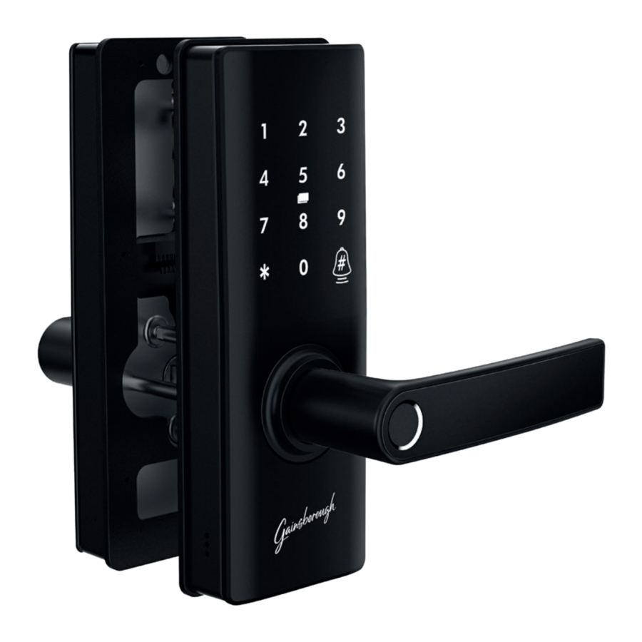
This Smart Entrance Lock is designed to use a standard 54mm cutout. With a fingerprint sensor and keypad, being locked out can become a thing of the past. Install the Grid Connect mobile app, available for both iPhone and Android devices to control and monitor your lock from your mobile device. Add an optional Bluetooth hub to enable access from anywhere.
The Grid Connect app is free to download and is available from the Apple App Store and Google Play. Check grid-connect.com.au for minimum device requirements.
MONITOR FROM ANYWHERE

Download from:


CONTENTS


- Front panel and rubber seal
- Back panel
- Latch
- Strike plate and box
- Mounting screws and spindles
- Mounting bracket and rubber seal
- Drill template
- 2 x Mechanical keys
- 2 x RFID tags
- 4 x AA batteries
- Reset pin
IDENTIFICATION

INSTALLATION - Contents
PLEASE READ THESE INSTRUCTIONS CAREFULLY. Failure to follow these instructions could affect the product's function or result in damage to the product.
- For your safety, take care when operating tools during installation.
- Install the product while the door is open. Do not close the door until you check that the product is operating correctly.
- Do not use excessive force or sharp objects to press the touchscreen.
- Do not install the batteries until you complete the installation.
- The lock should only be serviced by a professional technician. You must not modify/repair the product without authorization.


- Drill Template
- Front panel with rubber seal
- Back panel
- Mounting bracket with rubber seal (for back panel)
- 2 x Mechanical keys
- 4 x AA batteries
- Latch
- 2 x RFID tags
- Strike plate
- 6 x Door screws
-
- 1 x Spindle (60mm)
- 1 x Spindle (80mm)
- 3 x Screw Standoffs
-
- 3 x Front panel screws (25mm)
- 3 x Front panel screws (35mm)
- 3 x Back panel screws
- Reset Pin
INSTALLATION

Door preparation
Additional material including installation videos are available on the Gainsborough website: gainsboroughhardware.com.au
OPTION A: PREPARATION - REPLACING AN EXISTING LOCK*
* Note: If you are having trouble removing your existing lock, please contact a locksmith or the manufacturer of your existing door hardware for assistance.

- Remove your existing door handle. Most handles can be unscrewed from the indoor side.
- Check that your door meets the installation requirements:
- Standard 54mm diameter cut-out, with sufficient clearance on all sides to fit this product.
- Backset of 60mm or 70mm from edge of door to centre of cut-out.
- Door thickness between 32mm and 50mm.
- Remove the latch from the side of the door.
OPTION B: PREPARATION - NEW DOORS

Professional installation is recommended for new doors.

- Your door must have a thickness of between 32mm and 50mm.
- Using an installation kit (not included) or the drill template, create a standard cut-out:
- 54mm diameter cut-out centred 60mm back from the edge of the door.
- 25mm hole centred along the edge of the door through to the 54mm cut-out. (Note: The drill template can be used for vertical alignment only, horizontal position will vary depending on your door thickness.)
- Screw holes to install the latch and strike.
- Rectangular cut-out for flush installation of the latch and strike.
- Install the strike plate and box to the door frame.
Lock preparation
INSTALLATION - BOTH NEW AND EXISTING DOORS

- Identify whether your door is left-hinged or righthinged when viewed from the outside. Your door lock is set up for right-hinged doors out of the box. If you have a right-hinged door, skip to step 2. If you have a left-hinged door, continue to step 1.b.
- To change from righthinged door to left-hinged door setup, remove handing screw from the drive plate, rotate handle to opposite side and reinstall screw.
- Repeat this procedure for the back panel, removing the screw before rotating the handle up and around to the other side and securing the screw.
- Secure the latch to your door edge using the provided screws
![]() , ensuring that the latch orientation and backset are set correctly.
, ensuring that the latch orientation and backset are set correctly.

 ,
, 
- The bevelled edge of the latch should face the strike plate so that it will retract automatically.
- For most installations, the adjustable latch should be kept in the shorter position for a 60mm backset. If you are installing at a backset of 70mm from the edge of the door to the centre of the cut-out, push the spindle slot out to the 70mm marking.
- The latch must be screwed in before proceeding to the next step.
Front panel
- Fit the spindle
![]() (32- 40mm door thickness) or
(32- 40mm door thickness) or ![]() (41-50mm door thickness) and three screw standoffs
(41-50mm door thickness) and three screw standoffs ![]() into the front panel. Line up the protrusion on the spindle with the slot on the front panel and press in while inserting the spindle to lock it into place.
into the front panel. Line up the protrusion on the spindle with the slot on the front panel and press in while inserting the spindle to lock it into place.

- Install rubber seal to front panel.


 into the


- Hold the front panel against the outside of your door, aligning the spindle, standoffs, and cable with the holes in your door and latch. Push the front panel in until it is flush against the door, and hold it in place until the end of the next step.
- From the inside of your door, install the mounting plate and second rubber seal, ensuring that the spindle passes through the round hole and the cable through the rectangular cut-out. Using the three provided
![]() (32-40mm door thickness) or
(32-40mm door thickness) or ![]() (41-50mm door thickness) screws, secure the mounting plate to the front panel. When tightening the screws, check that the front panel is aligned correctly. Optional: Install additional screws
(41-50mm door thickness) screws, secure the mounting plate to the front panel. When tightening the screws, check that the front panel is aligned correctly. Optional: Install additional screws ![]() to secure the top of the mounting plate to the door.
to secure the top of the mounting plate to the door.


 to secure the top of
 Back panel

-
- Remove the battery cover from the back panel, then connect the wire from the front panel to the connector near the centre of the back panel. Press firmly to ensure that the cable is properly connected.
- Carefully position wire in cutout in rear of battery compartment.
-
- Fit the back panel against the mounting plate, before securing with three screws
![]() .
. - Install 4 AA batteries and replace the battery cover. Test that the indoor handle retracts the latch, and that the front panel can open the latch only after touching the fingerprint sensor.
- Fit the back panel against the mounting plate, before securing with three screws
 .
.
APP PAIRING


Reference phone screens on the proceeding pages may vary depending on the operating system version of your phone and any updates to the Grid Connect app. Contact our customer service team if you are unsure on how to pair your product.
NEW ACCOUNT LOG IN SETUP
Download and install the  GRID Connect App from Play Store (Android) or App Store (iOS),
Then follow the prompts to create a new account or login to an existing account.
- On the Grid Connect app, press
![]() in the bottom right corner, then select auto scan.
in the bottom right corner, then select auto scan.
The GRID Connect app will need access to Bluetooth to find your lock. - Press the fingerprint sensor to wake the device.
- Once the device is discovered, follow the prompts to complete the pairing process.
NOTE: If your lock is reset or removed from the app, it may be unlocked and discoverable until it is paired.
Optional: Add a Grid Connect Bluetooth hub (sold separately) to connect the lock to Wi-Fi and manage your door access from anywhere.
Follow the instructions provided with the hub to pair it to your account and bind your lock.
![]()

Visit our website for further Online Assistance or contact our Customer Service Team
grid-connect.com.au
1300 267 168
(toll free)
SHARING ACCESS
Your lock can be used by other users via app access or registering fingerprints, codes or tags. There are five ways to share access, see below to check which is best for you.
Secure mode restricts access to administrator users, app unlock and physical keys only. Use the switch on the interior panel to enable or disable secure mode.
Note: Administrators and primary users are added to the app location that your lock is paired to. Home members that have access to the location will gain access to your lock, and newly added administrators and primary users will be able to use all other devices in the location.
Not sure if you've shared access to your location? Tap on the menu icon > location and room setup > select your location. Anyone listed under 'home members' will have access to your lock.
USER TYPES

TROUBLE SHOOTING
| How do I unlock my door if the lock has run out of battery? | If your lock has run out of battery, you can still unlock the door using the mechanical keys provided. Alternatively, the lock can be powered by a portable 5Vdc USB power source, such as a power bank, and then unlocked as usual. After unlocking, you should replace the batteries as soon as possible with 4 new AA alkaline batteries. |
| How do I activate the lock after entering an incorrect code or fingerprint too many times? | If the lock receives too many invalid unlock attempts, it will be temporarily disabled for security reasons. Please wait for a few minutes and try again. |
| If I forget my GRID Connect app account password, how can I reset my password? | If you forget your password, you can tap forgot password and enter your GRID Connect registered account details to get a verification code and reset your password. |
| When I try to register for an account, the app tries to load, but does not progress to the next page. How can I fix this? |
|
Documents / Resources
References
![grid-connect.com.au]() Grid Connect | The Home for Home Automation
Grid Connect | The Home for Home Automation![www.apple.com]() App Store - Apple
App Store - Apple![play.google.com]() Google Play
Google Play![gainsboroughhardware.com.au]() Gainsborough Hardware Home
Gainsborough Hardware Home

Download manual
Here you can download full pdf version of manual, it may contain additional safety instructions, warranty information, FCC rules, etc.
Advertisement


Need help?
Do you have a question about the LIBERTY and is the answer not in the manual?
Questions and answers