FS S390O-24T4S-R, S3900-24F4S-R, S3900-48T6S-R, S3900 Series Manual
- Quick start manual (63 pages) ,
- Stacking configuration manual (8 pages) ,
- Configuration manual (5 pages)
Advertisement
Introduction
Thank you for choosing S3900 Series Stackable Managed Switches. This guide is designed to familiarize you with the layout of the switches and describes how to deploy them in your network.

Accessories


NOTE: This power cord cannot be used with other devices, and other power cords should not be used with this device.
NOTE: S3900 series switches have dust plugs delivered with them. Keep the dust plugs properly and use them to protect idle optical ports.
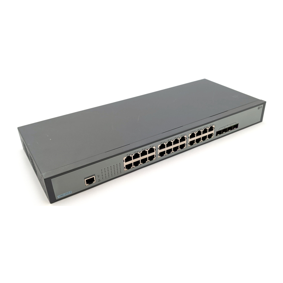
Hardware Overview
Front Panel Ports

| Ports | Description |
| RJ45 | 10/100/1000 BASE-T ports for Ethernet connection |
| SFP | SFP ports for 1G connection |
| SFP+ | SFP+ ports for 1/10G connection |
| CONSOLE | An RJ45 console port for serial management |
| COMBO | One RJ45 port and one SFP port, with one port active at a time |
Front Panel LEDs

| LEDs | Status | Description |
| PWR | Green | The switch is powered on. |
| SYS | Green | The system is working properly. |
| Blinking Green | The system is started normally. | |
| Off | The system is not working properly. | |
| Link/Act | Green | Data is being transmitted or received. |
| Off | No signal transmission. | |
| RJ45/SFP+ | Blinking Green | Data is being transmitted or received. |
| Off | No device is connected to the corresponding port. |
Back Panel

| Button | Description |
| Power switch | ON means the power is switched on, while OFF means the power is cut off. |
Installation Requirements
Only professionals are allowed to install or replace the switch. Before you begin the installation, make sure that you have the following:
- Screwdriver
- Static-proof wristband
- Ethernet cable
- Other Ethernet terminal devices
- Control terminal
Site Environment:
- Do not operate it in an area that exceeds an ambient temperature of 50°C.
- The installation site must be well ventilated. Ensure that there is adequate air flow around the switch.
- Be sure that the switch is level and stable to avoid any hazardous conditions.
- Do not install the equipment in a dusty environment.
- The installation site must be free from leaking or dripping water, heavy dew, and humidity.
- Ensure rack and working platforms are well earthed.
Mounting the Switch
Desk Mounting

- Attach four rubber pads to the bottom.
- Place the chassis on a desk.
NOTE: Do not put things weighing 4.5 kg or over 4.5 kg on the top of the switch.
Rack Mounting
- Secure the mounting brackets to the two sides of the switch with M4 screws.

- Attach the switch to the rack using M6 screws and cage nuts.


Grounding the Switch

- Connect one end of the grounding cable to a proper earth ground, such as the rack in which the switch is mounted.
- Secure the grounding lug to the grounding point on the switch back panel with the screw and washers.

The earth connection must not be removed unless all supply connections have been disconnected.
Connecting the Power

- Plug the AC power cord into the power port on the back of the switch.
- Connect the other end of the power cord to an AC power source.

Do not install power cable while the power is on.
Connecting the RJ45 Ports

- Connect an Ethernet cable to the RJ45 port of a computer, printer, network storage, or other network devices.
- Connect the other end of the Ethernet cable to the RJ45 port of the switch.
Connecting the SFP+/SFP Ports

- Plug the compatible SFP+/SFP transceiver into the SFP+/SFP port. (Only S3900-24F4S-R has the SFP ports.)
- Connect a fiber optic cable to the fiber transceiver. Then connect the other end of the cable to another fiber device.
Laser beams will cause eye damage. Do not look into bores of transceivers or optical fibers without eye protection.
Connecting the Console Port

- Insert the RJ45 connector into the RJ45 console port on the front of the switch.
- Connect the DB9 female connector of the console cable to RS-232 serial port on the computer.
Stacking the S3900 Series Switches
S3900-24T4S-R&S3900-24F4S-R support 8 units hybrid-stacking together. S3900-48T6S-R supports 6 units stacking between same models. Switches can be physically stacked using optical fiber cables connected to SFP+ transceivers, or IOG Direct Attach Cables (DAC). All SFP+ ports on the switch can be used for physical stacking.

Configuring the Switch
Configuring the Switch Using the Web-based Interface
- Connect your computer to any Ethernet port of the switch using the network cable.
- Set the IP address of the computer to 192.168.1.x. ("x" is any number from 2 to 254.)
![]()
- Open a browser, type http://192.168.1.1, and enter the default username and password.
- Click Login to display the web-based configuration page.

Configuring the Switch Using the Console Port
- Connect a computer to the switch's console port using the supplied console cable.
- Start the terminal simulation software such as HyperTerminal on the computer.
- Set the parameters of the HyperTerminal: 115200 bits per second, 8 data bits, no parity, 1 stop bit and no flow control.
- After setting the parameters, click Connect to enter.
![]()

Troubleshooting
1/10G Port is not Working
In the case of compatible cables and transceivers, the port cannot be up, please try to modify the port mode to adapt or force the port speed to 1G/10G.
Connecting the Switch Remotely Unsuccessfully
- Test network connectivity through ping.
- If the network is reachable, try restarting the switch.
- Check if the corresponding service is enabled.
The Port is not Working, the LED Indicator is Off
- Ensure the switch ports are in the no shutdown state.
- Check if the switch can read the DDM information.
- Check if the port speed setting is correct.
- Try looping the switch cable.
Online Resources
- Download
https://www.fs.com/products_support.html - Help Center
https://www.fs.com/service/fs_support.html - Contact Us
https://www.fs.com/contact_us.html
Documents / Resources
References
HPC, Data Centre, Enterprise, Telecom - FS.com Europe
HPC, Data Centre, Enterprise, Telecom - FS.com Europe
HPC, Data Centre, Enterprise, Telecom - FS.com Europe
Download manual
Here you can download full pdf version of manual, it may contain additional safety instructions, warranty information, FCC rules, etc.
Download FS S390O-24T4S-R, S3900-24F4S-R, S3900-48T6S-R, S3900 Series Manual
Advertisement


Need help?
Do you have a question about the S3900 Series and is the answer not in the manual?
Questions and answers