Asus TUF Gaming A16 Advantage Edition Series (FA617X) Manual
- Service manual (32 pages) ,
- Service manual (32 pages)
Advertisement
- 1 Service Overview
- 2 Series Overview
- 3 Components Top View
- 4 Components Bottom View
- 5 Repair Overview
- 6 Appropriate Tools
- 7 BOTTOM CASE
- 8 DISCONNECT BATTERY CONNECTOR
- 9 SSD
- 10 DDR
- 11 BATTERY
- 12 USB BOARD
- 13 Wi-Fi CARD
- 14 THERMAL MODULE
- 15 FAN and MAIN BOARD
- 16 MAIN BOARD
- 17 SPEAKER
- 18 LED BOARD
- 19 KEYBOARD MODULE
- 20 LCD BEZEL
- 21 LCD PANEL
- 22 LCD Cover
- 23 LCD PANEL and LCD Cover
- 24 Safety precautions
- 25 Documents / Resources
Service Overview
- Carefully read through this Service Guide for a look at various components of the device before performing any service and repairs.
- To provide the best service, we have provided the below information for technicians from distributors and resellers to perform the complete device disassembly and assembly. Before performing the procedures, please be sure to read through the overview in this service guide for component overview to avoid any unwarranted damages to the device hardware.
- The following contents include all part numbers mentioned in the service guide are used for reference only, if you need the exact part number for ordering, please refer to the OrderBook.
- Due to sales policy difference, the components might have different specifications on the same series product, please refer to E-manual by model.
Due to sales policy difference, the components may have different specifications on the same model. If you have any operational issues, please contact the service hotline.
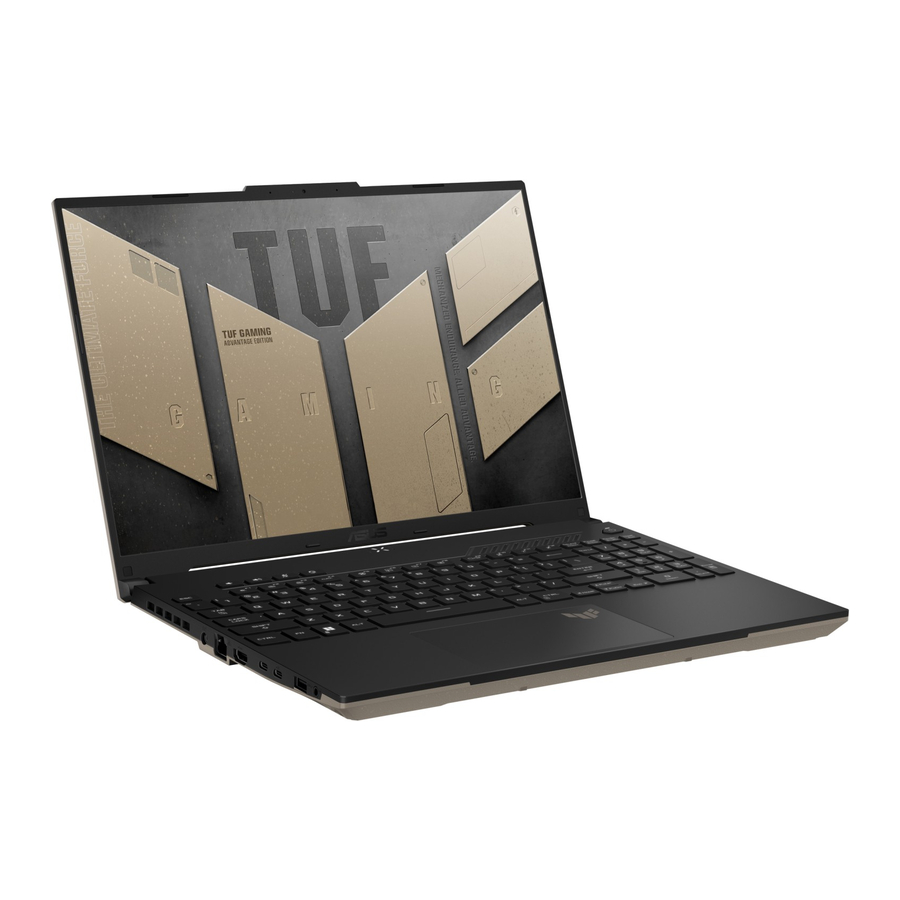
Series Overview
Front View

- Array microphones
- Camera indicator
- Camera
- Display panel
- Status indicators
- Keyboard
- Capital lock indicator
- Air vents
- Power button
- Numeric keypad
- Touchpad
Bottom View

- Air vents
- Audio speakers
- Bottom cover
Right View

- USB 3.2 Gen 1 port
- Air vents
- Kensington® security slot
Left View

- Air vents(on selected models)
- Power(DC) input port
- LAN port
- HDMI output port
- USB 3.2 Gen 2 Type-C®/DisplayPort/DisplayPort combo port

- USB 3.2 Gen 2 Type-C®/DisplayPort/Power Delivery combo port
- USB 3.2 Gen 1 port
- Headphone/Headset/Microphone jack
Components Top View

Components Bottom View

Repair Overview
This chapter describes disassembly and assembly (Assemble document please look up from the last page), please follow the information provided in this section to perform the complete disassembly procedure.
Precautions:
Before you perform any service or repair on the notebook, please pay special attention to the cautions prevent any damages to the notebook.
- Be sure that the notebook is powered down.
- Before disassembling any part, please disconnect all power source. ex: AC plug/Battery connector/Power protect screw etc.
- Remove all rings, watches and any other metal objects from your hands.
![]()
- Always wear a ground strap on your hand to protect the notebook from static discharge.
- Please refer to "ANSI ESD S20.20" about ESD protection measure.
- Put the disassembled parts in the functional PE BAG to avoid any damages of the A/B/C/D part.
![]()
- The maintenance environment temperature is 20-30 ℃ and humidity is 40% - 70%.
- To avoid scratching on the surface of machine; please use anti-static and soft materials to put on desk in repair environment as below photo.
![]()


- Screw Appearance Criteria: If the screws have the following damaged appearance, please do not use.
- Shape deformed.
- Damaged head – unable to drive in or the stripped screw.
- Damaged unable to securely tighten.
- Paint scratched off.
- Rusty
![]()
- The following chapter includes all part numbers mentioned in service guide are used for reference only, actual part name depends on different SKU, if you need the exact part number for ordering, please refer to the Orderbook.
- Due to sales policy difference, the components may have different specifications on the same model. Please note that all pictures and components shown on Service Guide are for disassembly/assembly description purpose only, so please refer to the actual product for disassemble/assemble.

Appropriate Tools
Please prepare and select the appropriate tools to disassemble/assemble for the ASUS TUF Gaming A17 (FA707N) series notebook.

BOTTOM CASE
Disassembly Notice

The device has an Ambient Light Sensor (ALS) for power-off protection function.

Step 1 : Remove screws*11pcs.
Step 2 : Use the non-conductive pry tool to pry the bottom case.
DISCONNECT BATTERY CONNECTOR
Disassembly Notice
The device has an Ambient Light Sensor (ALS) for power-off protection function.
 Before disassembly battery connector, please be sure to pull out adapter and disconnect the battery more than ten seconds in order to avoid IC damage.

Step 1 : Use the non-conductive pry tool to push iron sheet.
Step 2 : Use the non-conductive pry tool to disconnect battery connector.
 Note : Please disconnect the red cable side first.
Assembly Notice
To prevent getting a short circuit or an electric shock accident, please follow the below steps to connect the battery connector.

Step 1 : Use the non-conductive pry tool to connect the black cable side first, then connect the red cable side.
Step 2 : Use the non-conductive pry tool to push the iron sheet.
SSD
Disassembly Notice
The device has an Ambient Light Sensor (ALS) for power-off protection function.

Step 1 : Tear off the (yellow mark) DIMM COVER MYLAR.

Step 2 : Remove the (red mark) screws and M.2 card (SSD).

Step 3 : Remove the AL FOIL and ABSORBER from the left M.2 card (SSD).

*Please keep these parts, they will be reused for new SSD installation.
Assembly Notice
The device has an Ambient Light Sensor (ALS) for power-off protection function.
- Please use this SSD1 slot as first priority.
![]()
- Paste the ABSORBER*1pc on both of the left-M.2 card (SSD)

- Put the left-M.2 card (SSD) into the AL FOIL*1pc before inserting it into the left-SSD slot. (left SSD

- When installing the SSD, please keep the SSD less than 15 degrees with the motherboard, and then insert the SSD.

- Align and insert the SSD into the module slot, then secure the SSD in place by fastening screw

- After installing the SSD, please paste the DIMM COVER MYLAR on below location. (yellow mark)


DDR
Disassembly Notice
The device has an Ambient Light Sensor (ALS) for power-off protection function.
Step 1 : Tear off the DDR AL FOIL MYLAR

Step 2 : Unlock and remove the RAM module.

Step 3 : Tear off the ABSORBERS from RAM front and back side

Step 4 : Paste the DDR LABEL on DDR.

*Notice: Please keep these parts, it will be reused for new DDR installation.
Step 5 : Paste the DDR LABEL on DDR.

For Step 4 - 5:
If the DDR label is torn off during the removal of the ABSORBER, please remember to paste it back on the DDR to avoid the situation that it cannot be returned to the warehouse.
Assembly Notice
The device has an Ambient Light Sensor (ALS) for power-off protection function.
Please paste ABSORBERS on the front and back sides of RAM before installing the Memory Module.
- Paste the two ABSORBERS on the new RAM front and back side.

- Align and insert the new RAM module at 30° into the memory slot. Once properly inserted, push down the RAM module until it clicks in place.
![]()
- After installing the DDR, please paste the MYLAR on below location. (yellow mark)


BATTERY
Disassembly Notice
The device has an Ambient Light Sensor (ALS) for power-off protection function.
Before disassembly battery connector, please be sure to pull out adapter and disconnect the battery more than ten seconds in order to IC damage.

Step 1 : Remove the (red mark) screws*3 pcs.

Step 2 : Take out Battery then remove the Battery cable.

USB BOARD
Disassembly Notice
The device has an Ambient Light Sensor (ALS) for power-off protection function.

Step 1 : Disconnect and remove the USB FPC.

Step 2 : Remove the screw*1pc then remove USB BOARD.
Wi-Fi CARD
Disassembly Notice
The device has an Ambient Light Sensor (ALS) for power-off protection function.


Step 1 : Disconnect the RF CABLE connectors*2pcs.
Step 2 : Remove the screw*1pc.
Step 3 : Remove Wi-Fi CARD.
Assembly Notice
Please according to below image to assemble the Wi-Fi module.

THERMAL MODULE
Disassembly Notice
The device has an Ambient Light Sensor (ALS) for power-off protection function.


Step 1 : Disconnect (yellow mark) EDP connector*1pc.
Step 2 : Release the EDP cable.
Step 3 : Follow the reverse screws numbers to remove screws*10pcs.
Step 4 : Remove THERMAL MODULE.
Recommend that the force point is at green block, and pull up thermal module to take it out. Do not pull up at red block and also notice the thermal pipe should not have deformation.
Assembly Notice
Step-1
- THERMAL MODULE Location:[VRAM/CHOKE/MOS]
Material: FCR-AS Grease - MB Location:[GPU/CPU]
Material:
Main (GA500 Grease)
Substitute (PSX Thermal pad)
Step-2
Please follow the screws numbers to lock screws *8pcs.

Thermal paste, thermal pads, liquid metal, or other thermal interface materials must be thoroughly removed and replaced if this component is removed. Ensure that replacement materials are available before proceeding, or contact an authorized service center for assistance.

The heat sink contains liquid metal and should only be removed by authorized service personnel. Significant damage may occur to motherboard components if the heat sink is improperly removed.
FAN and MAIN BOARD
Disassembly Notice
The device has an Ambient Light Sensor (ALS) for power-off protection function.


Step 1 : Disconnect (yellow mark) connectors*7pcs.
Step 2 : Remove(Red mark) screws*9pcs.
Step 3 : Remove CPU FAN and GPU FAN.
Step 4 : Remove the Main board.
Assembly Notice
If FFC is damage during disassembly, please replace new one. Here are some samples of FFC damage:

Please use the correct technique to take fans off to avoid getting out of shape.

MAIN BOARD
Mainboard connector placement

Materials on mainboard
TOP SIDE

BOT SIDE

SPEAKER
Disassembly Notice
The device has an Ambient Light Sensor (ALS) for power-off protection function.
Step 1 : Remove SPEAKER.

Assembly Notice
For Speaker assembly, please follow the mark below to tidy cable.
Step 1: Tidy up the cable as illustrated also put the cable under the parts as shown in the red and yellow marks

LED BOARD
Disassembly Notice
The device has an Ambient Light Sensor (ALS) for power-off protection function.

Step 1 : Flip the (red mark) MYLAR on the LED Module.
Step 2 : Release the gasket of the cable.
Step 3 : Remove the LED Module.
Step 4 : Disconnect the LED FFC.
Assembly Notice
If FFC is damage during disassembly, please replace new one. Here are some samples of FFC damage:

The TOP LED SPONGE and LED BD AL FOIL are not reusable after the disassembly LED BOARD, before assembly LED BOARD Module, please follow the steps below to paste the new TOP LED SPONGE and LED BD AL FOIL.

KEYBOARD MODULE
Disassembly Notice
The device has an Ambient Light Sensor (ALS) for power-off protection function.


Step 1 : Disconnect the (yellow mark) TP FFC.
Step 2 : Remove screws*3pcs.
Step 3 : Remove the touchpad module.
Step 4 : Remove (orange mark) screws*4pcs.
Step 5 : Lift up and separate the Keyboard module.
Assembly Notice
Please refer below picture to organize EDP cable.

If FFC is damage during disassembly, please replace new one. Here are some samples of FFC damage:

Assembly Notice
The device has an Ambient Light Sensor (ALS) for power-off protection function.
For Antenna assembly, please follow the mark below to tidy cable.

LCD BEZEL
Disassembly Notice
The device has an Ambient Light Sensor (ALS) for power-off protection function.
Step 1 : Remove BEZEL COSMETIC MYLAR*2pcs.
Step 2 : Remove screws*2pcs.
Step 3 : Remove LCD BEZEL.


Step 3-1~3-3, Start from the middle area of each side of bezel, Using the forefinger to hold the outer edge firmly and the thumb flipping the bezel inner edge outward to release the hooks as indicated in the diagram shown. (It can be helpful, if holding the bezel outer edge firmly with forefinger.)

Step 3-4 Due to some tapes behind the lower edge of bezel, please using plastic blade to teardown the bezel. Please follow the direction shown in the red arrow, to move plastic blade from left to right and peel the bezel away slowly. While peeling, please move the blade in the parallel direction to the panel and pressing the black Mylar downward (As circled in green) to ensure the black Mylar and the tape behind the bezel are well separated.
Please move blade slowly to separate the bezel away and must press the black Mylar downward with panel parallel direction.

Assembly Notice
When reuse the LCD BEZEL:
Please paste new LCD BEZEL ADHESIVE before assembly BEZEL. (New LCD BEZEL already contains LCD BEZEL ADHESIVE *4pcs)

LCD PANEL
Disassembly Notice
The device has an Ambient Light Sensor (ALS) for power-off protection function.

Step 1 : Remove screws*6pcs and hinges*2pcs.

Step 2 : Pull out LCD adhesives*2pcs.

Please pull the adhesive up about 30 degree slowly, and don't pull out the tape in vertical direction!
Step 3 : Flip up the panel and disconnect the EDP cable.

LCD Cover
Disassembly Notice
The device has an Ambient Light Sensor (ALS) for power-off protection function.

Step 1 : Disconnect the(Red mark) Camera connector.
Step 2 : Release the(yellow mark) tape.
Step 3 : Remove EDP cable.
Step 4 : Remove the Camera module.
Step 5 : Remove MIC RUBBER*2pcs.
Assembly Notice
 Please follow the blue mark to tidy up EDP cable.

LCD PANEL and LCD Cover
Assembly Notice
The device has an Ambient Light Sensor (ALS) for power-off protection function.
- When reuse the LCD Panel or BEZEL: (The following is an operation example) Please use the fingertip to clean the residual glue on PANEL or BEZEL.

- Clean the back of the LCD PANEL:
Before assembling the LCD panel, use a dust-free cloth and a small amount of alcohol to clean the back of the panel.
![]()
- When replace the LCD and reuse the LCD COVER:
Please paste new LCD COVER TAPE *2pcs on cover. Don't over the marking line, then Flatten by hand.
![]()
- When assembly the LCD PANEL:

Step 1: Remove release paper of LCD Adhesive*2pcs.
Step 2: Assembly and align the LCD to the upper side of the LCD Cover


Safety precautions
- Keep liquids or moisture away from your Notebook PC before installing or removing any components.
- Ensure to place your Notebook PC on a stable surface before installing or removing any components.
- Detach the clip or flap before removing the signal cables to prevent damage.
- Disconnect the power plug by pulling the plug evenly to avoid damage. Ensure to connect the signal cables in the correct orientation.
- Disconnect all power cables and remove the battery pack (if applicable) before cleaning your Notebook PC with liquid detergent to avoid risk of electric shock.
- Disconnect all power cables and remove the battery pack (if applicable) before installing or removing any components. Ensure to read and follow the instructions in the manual.
- Before handling components, use a grounded wrist strap or touch a safely grounded object to avoid damaging them due to static electricity.
- Keep liquids or moisture away from your Notebook PC to avoid short circuits.
- Hold components by the edges to avoid touching the ICs.
- Ensure to properly install all the components before connecting the AC power.
- Do not use power adapters or batteries from other devices to reduce the risk of injury to persons due to fire or explosion. Use only certified power adapters or batteries supplied by the manufacturer or authorized retailers.
- Ensure to install the correct screw models on your Notebook PC to prevent damage.
Documents / ResourcesDownload manual
Here you can download full pdf version of manual, it may contain additional safety instructions, warranty information, FCC rules, etc.
Download Asus TUF Gaming A16 Advantage Edition Series (FA617X) Manual
Advertisement


Need help?
Do you have a question about the TUF Gaming A16 Advantage Edition Series and is the answer not in the manual?
Questions and answers