Table of Contents
Advertisement
Owner's Manual
Thank you, and congratulations on your choice of the Edirol SD-90.
Before using this unit, carefully read the sections entitled: "IMPORTANT
SAFETY INSTRUCTIONS" (Owner's manual p. 2), "USING THE UNIT
SAFELY" (Owner's manual p. 3, 4), and "IMPORTANT NOTES" (Owner's
manual p. 5). These sections provide important information concerning the
proper operation of the unit. Additionally, in order to feel assured that you
have gained a good grasp of every feature provided by your new unit, Owner's
manual should be read in its entirety. The manual should be saved and kept on
hand as a convenient reference.
Copyright © 2001 ROLAND CORPORATION
All rights reserved. No part of this publication may be reproduced in any form
without the written permission of ROLAND CORPORATION.
Advertisement
Table of Contents

Related Manuals for Edirol Studio Canvas SD-90


Summary of Contents for Edirol Studio Canvas SD-90
- Page 1 Owner’s Manual Thank you, and congratulations on your choice of the Edirol SD-90. Before using this unit, carefully read the sections entitled: “IMPORTANT SAFETY INSTRUCTIONS” (Owner’s manual p. 2), “USING THE UNIT SAFELY” (Owner’s manual p. 3, 4), and “IMPORTANT NOTES” (Owner’s manual p.
- Page 2 The wire which is coloured BROWN must be connected to the terminal which is marked with the letter L or coloured RED. For the USA DECLARATION OF CONFORMITY Compliance Information Statement Model Name : SD-90 Type of Equipment : USB Audio & MIDI Processing Unit Responsible Party : Edirol Corporation North America...
-
Page 3: Using The Unit Safely
Refer all servicing to your retailer, ....................the nearest Roland / EDIROL Service Center, • This unit, either alone or in combination with or an authorized Roland distributor, as listed an amplifier and headphones or speakers, on the "Information"... - Page 4 ....................eventually melt through....................• Before using the unit in a foreign country, consult with your retailer, the nearest Roland Service Center, or an authorized Roland distributor, as listed on the "Information" page....................
-
Page 5: Important Notes
• Before connecting this unit to other devices, turn off • Use a cable from Roland to make the connection. If the power to all units. This will help prevent using some other make of connection cable, please malfunctions and/or damage to speakers or other note the following precautions. -
Page 6: Table Of Contents
Editing in the list display..................30 Editing parameters that are common to all parts ..........31 About parameters that can be edited from the SD-90’s panel........32 Part parameters (GM2 mode, Native mode) ............32 Part parameters (Native mode) ................36... - Page 7 Contents Using the effects of the internal sound generator....38 About the sound generator effects .................. 38 Editing the sound generator effects................. 39 Parameters that can be edited in GM2 mode..............40 Reverb (System Effect) ................... 40 Chorus (System Effect)................... 40 EQ (Equalizer) ......................
- Page 8 Adjusting the contrast of the display ................76 Setting the system tempo ....................76 Restoring the factory settings................... 76 Controlling the SD-90 via MIDI..........77 Controlling the internal sound generator............... 77 Switching the sound generator mode..............77 Switching the sound set ..................79 Switching the type of part ..................
-
Page 9: Introduction
SD-90 with your computer. Please read this first. • The User Guide explains how to use all the basic features of the SD-90. After you have made settings for the SD-90 as described in the Startup Manual, and have verified that it produces sound correctly, refer to the User Guide as necessary, depending on the purpose you have in mind. -
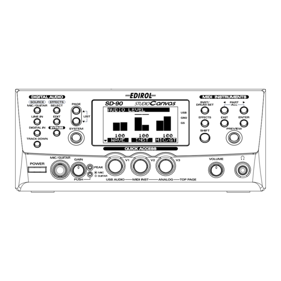
Page 10: Names Of Things And What They Do
List display" (p. 54)). SYSTEM Button Use this button to make settings that affect the entire SD-90 system ("System-related settings" (p. 69)). Display This shows various types of information (such as level meters or parameter values) related to the current state. - Page 11 This button is used in conjunction with other buttons to change the function of the other button. fig.1-01a 15 POWER Switch This turns the power of the SD-90 on/off. The power is on when the Lower position Upper position switch is pressed in, and the power is off when the switch is in the outward position.
-
Page 12: Rear Panel
■ Rear Panel fig.1-02 USB Connector A USB cable can be used to connect the SD-90 to your computer. In USB mode, audio signals and MIDI messages can be exchanged through this cable. MIDI Connectors These connectors can be connected to other MIDI devices, such as a sequencer, allowing the exchange of MIDI messages ("Controlling the SD-90 via MIDI"... -
Page 13: Basic Operation
Please make sure to read this section, since it is sure to help you gain a better understanding of your new unit. How the SD-90 is organized The SD-90 consists of the following three blocks. For details on each block, refer to the corresponding page. fig.2-01... -
Page 14: Operations In The Basic Screen
The SD-90 contains a diverse array of sounds, ranging from instrumental sounds such as piano/organ/ guitar for an ensemble, to sound effects such as birdsong and telephone ringers. Each of these sounds is called an instrument. Here’s how to select instruments and listen to the variety of sounds that the SD-90 provides. -
Page 15: Auditioning The Sounds (Preview)
Basic operation ■ Auditioning the sounds (Preview) On the SD-90, sounds are specified using two numbers: the instrument number and the variation number. By pressing [PREVIEW] you can audition the currently selected sound. fig.2-03a 1, 4 Press [INST/DRUM SET]. Press [PREVIEW]. While you continue pressing [PREVIEW], the button will light and a phrase will play. -
Page 16: Adjusting The Brightness Of The Display (Contrast)
■ Adjusting the brightness of the display (Contrast) Immediately after the power is turned on, or after the SD-90 has been used for an extended period, or depending on the conditions in which it is placed, the characters or icons in the display screen may become difficult to read. -
Page 17: Using The Internal Sound Generator
It uses the same instrument files and sound sets as GM2 mode, and provides a greater number of editable parameters. In addition, it provides two special sound sets that collect the most distinctive of the sounds of the SD-90. GS mode This sound generator mode supports the “GS”... -
Page 18: About Gm2/Native Modes
MFX. Special This sound set can be used only in Native mode. It consists mainly of the best sounds of the SD-90 from the Enhanced set, and also includes highly original sounds not defined by GM2. As with the Enhanced set, most sounds use multi-effects (MFX). -
Page 19: About Parts And Sounds
Using the internal sound generator About parts and sounds The SD-90 is able to produce 32 different sounds at once. A sound generator such as the SD-90 that is able to produce many different sounds simultaneously is called a “multitimbral sound module.” “Timbre”... -
Page 20: Switching The Sound Generator Mode
Using the internal sound generator Switching the sound generator mode Here’s how to switch the sound generator mode. The sound generator mode can be switched from the front panel, or by MIDI messages from an external device. Please be aware that the sound generator will be initialized when you switch the sound generator mode. -
Page 21: Selecting A Part
Using the internal sound generator Selecting a part Here’s how to select the part that you want to edit. fig.5-03 1, 3 Press [INST/DRUM SET]. fig.5-03a_67.2 Press [PART ] or [PART ] to select the part to be edited. The number of the part currently being edited is indicated at the bottom of the display. -
Page 22: Selecting The Type Of Part (Inst/Drum)
Using the internal sound generator Selecting the type of part (INST/DRUM) Here’s how to select the type (Part Mode) for each part. fig.5-04 1, 4 Press [INST/DRUM SET]. Press [PAGE ] once. fig.5-04a_67.2 Turn the [V1] knob to select the desired part mode (INST or DRUM). -
Page 23: Selecting The Sound Set
Using the internal sound generator Selecting the sound set In GM2 mode you can choose one of four different sound sets. In Native mode you can choose one of six different sound sets. fig.5-05 1, 3 Press [INST/DRUM SET]. fig.5-05a_67.2 Turn the [V3] knob to select the desired sound set. -
Page 24: Selecting A Sound
Inst. For details on how to set the part type to Inst, refer to "Selecting the type of part (INST/DRUM)" (p. 22). On the SD-90, the sound of an Inst part is specified by two numbers: an Instrument number and a Variation number. There are 128 sounds whose variation number is 000, and these make up the basic sounds of the SD-90. -
Page 25: Selecting A Drum Set
Using the internal sound generator Selecting a drum set If the part type is Drum Set, use the following procedure to select a drum set. First make sure that the part type is Drum. For details on how to set the part type to Drum, refer to "Selecting the type of part (INST/ DRUM)"... -
Page 26: Muting/Soloing A Part
You can “mute” a specified part so that it will not sound. This is convenient when you want to play along to a backing provided by the SD-90 (“minus-one” playing). Conversely, you can “solo” a specified part so that the remaining parts will be muted. -
Page 27: Soloing A Part
Using the internal sound generator ■ Soloing a part When multiple parts are sounding, you can cause only the currently selected part to sound, allowing you to check the performance of that part. This is referred to as “soloing” the part. fig.5-09 1, 4 Press [INST/DRUM SET]. -
Page 28: About Parameters
“editing.” If you are using the SD-90 in GM2 mode or Native mode, some of the Part parameter values can be edited from the panel of the SD-90 itself. In other modes, parameter values cannot be edited from the panel of the SD-90. -
Page 29: Editing The Parameters
Parameters can be edited from the panel of the SD-90 only in GM2 mode and Native mode. * It is not possible to preserve the edited state of the audio mixer in the SD-90’s internal memory. Your edits will be lost when the power is turned off. -
Page 30: Editing In The List Display
Using the internal sound generator ■ Editing in the list display Part parameters can also be edited in a list display. This is convenient when you want to edit a larger number of parameters at once. fig.5-11 2, 4 Press [INST/DRUM SET]. fig.5-11a_67.2 Simultaneously press [PAGE ] and [PAGE ]. -
Page 31: Editing Parameters That Are Common To All Parts
Using the internal sound generator ■ Editing parameters that are common to all parts Here’s an example of how to edit parameters that are common to all parts. fig.5-12 Simultaneously press [PART ] and [PART ]. A screen will appear in which you can edit parameters for all parts. -
Page 32: About Parameters That Can Be Edited From The Sd-90'S Panel
Master Coarse Tuning On the SD-90, parameter values are specified for the Part. In other words, these parameters belong to the part, and not to the sound (instrument). For example, if you set Vibrato Rate to +20 and then select a different sound for that part, the Vibrato Rate of the newly selected sound will stay at +20, and will not be the default setting of +/-0. - Page 33 Filter You can adjust the tonal character of the sound by editing the filter values. The filters of the SD-90 are a type called Low Pass Filters, which pass the region of sound that lies below a specified frequency. This frequency is called the Cutoff Frequency.
- Page 34 Using the internal sound generator Envelope fig.p8-3j The sound of a musical instrument changes over time from the moment the note begins until it ends. Such change can be expressed Low pass filter characteristics by the graph shown below. The shape of this change is distinctive of Level that particular instrument, and is an important factor that allows us to recognize the type of instrument.
- Page 35 Using the internal sound generator Vibrato fig.p7-1j Delay Vibrato is an effect that cyclically modulates the pitch. By applying vibrato, you can make your Depth performance more expressive. Note On Rate Vibrato Rate [cc#76] -64–0–+63 This adjusts the speed (frequency) at which the pitch is modulated. Positive (+) settings will speed up the modulation, and negative (-) settings will slow down the modulation.
-
Page 36: Part Parameters (Native Mode)
Using the internal sound generator Scale/Octave Tuning Adjust -64–0–+63 Scale Tuning is a function that lets you make fine adjustments to the pitch of each note in the octave. You can make one octave of settings, and these settings will adjust the pitch of all octaves in the same way. Scale Tune allows you to play scales other than the conventional equal tempered scale. -
Page 37: Parameters Common To All Parts (Gm2 Mode, Native Mode)
415.3–440.0–466.2 Hz When you are playing in an ensemble with other instruments, or want to adjust the SD-90 to the tuning of another instrument, you can adjust the Master Tuning in a range from 415.3 Hz to 466.2 Hz. The displayed value (for example 440.0 Hz) is the frequency of the A4 note (note number 69). -
Page 38: Using The Effects Of The Internal Sound Generator
Using the effects of the internal sound generator About the sound generator effects The SD-90 contains the following four effects processors, and each can be set independently. Chorus Chorus is an effect that adds depth and spaciousness to the sound. -
Page 39: Editing The Sound Generator Effects
Using the effects of the internal sound generator Editing the sound generator effects You can edit the sound generator effects when the sound generator mode is either GM2 mode or Native mode. fig.6-01b Switch the sound generator to GM2 mode (or Native mode). For details on switching the sound generator mode, refer to "Switching the sound generator mode"... -
Page 40: Parameters That Can Be Edited In Gm2 Mode
The sound generator effect parameters that can be edited using the SD-90’s controls will differ depending on the sound generator mode (GM2 or Native). In the SD-90’s GM2 mode, you can edit the reverb and chorus parameters. The following parameters can be edited. -
Page 41: Eq (Equalizer)
Using the effects of the internal sound generator Mod Rate (Modulation Rate) 0–127 Specifies the speed (frequency) at which the chorus sound will be modulated. Higher settings produce faster modulation. Mod Depth (Modulation Depth) 0–127 Specifies the depth of modulation for the chorus sound. Higher settings will produce deeper modulation. Feedback 0–127 Specifies the level of the chorus sound that will be re-input to the chorus (i.e., the amount of feedback). -
Page 42: Parameters That Can Be Edited In Native Mode
Parameters that can be edited in Native mode The sound generator effect parameters that can be edited using the front panel of the SD-90 will differ depending on the sound generator mode (GM2 or Native mode). In the SD-90’s Native mode, you can edit the parameters of the two system effects and three MFX (multi-effects). - Page 43 Using the effects of the internal sound generator Feedback (Delay Feedback) 0–127 When the Type is DELAY or PAN-DELAY, this specifies the amount of delay sound that will be returned (fed back) to the input of the delay. Raising this value will cause the delay to continue repeating for a greater number of times.
-
Page 44: Chorus (System Effect)
Using the effects of the internal sound generator ■ Chorus (System Effect) On the SD-90, the chorus section can also be used as a delay. Here you can edit parameters that select either chorus or delay, and specify how the chorus/delay sound will be heard and output. -
Page 45: Mfx (Multi-Effects)
Using the effects of the internal sound generator Pre Delay (Chorus Pre Delay) 0.0–100 ms Specifies the amount of time that is to pass after the original sound has been heard before the chorus sound is heard. Increasing this value heightens the dispersal effect. Type (Filter Type) Specifies the type of filter. - Page 46 Using the effects of the internal sound generator MFX A-C Reverb Send Level (Multi-effect A–C Reverb Send Level) 0–127 Specifies the level at which the signal processed by the multi-effect will be sent to the Reverb effect. MFX A-C Control 1-4 Source (MFX A–C Control 1–4 Source) Specifies the control source that will modify the multi-effect parameter, and the sensitivity of the control.
-
Page 47: Eq (Equalizer)
Using the effects of the internal sound generator Specifying the output destination of the part PART OUTPUT ASSIGN MFX, A, PATCH Specify where the output signal of the part will be sent. MFX: Output to MFX. Output the sound directly, without using MFX. PATCH: Use the settings of the sound (patch). -
Page 48: Using The Audio Mixer
Set the volume of the source * A block diagram (a diagram of internal connections) is printed on the top panel of the SD-90. You may wish to refer to this block diagram for a general understanding of the audio mixer. - Page 49 * Do not turn off the power while the settings are being stored (while the display indicates “SAVING...”). Doing so will result in the loss of all data stored within the SD-90. Press [SYSTEM] once again to return to the main screen.
-
Page 50: Digital Connections
When making digital connections, you must also make sure that the sampling frequency of the connected recorder, the sampling frequency of the SD-90, and the sampling frequency of the audio handled by the sequencer program on your computer are all set to the same setting. Use the following procedure to select the type of digital jack and the sampling frequency you will use. - Page 51 However, if a CD player or similar device is connected to the SD-90’s DIGITAL IN jack, and the incoming signal contains flags that prohibit digital copying, digital copying of the signal that is output from the DIGITAL OUTPUT jack will also be limited to a single generation.
-
Page 52: Selecting The Recording Source
On the SD-90 you can select the source that will be recorded on your computer simply by switching the routing. For example, if you want to monitor the sound of your guitar processed by the Guitar Multi effect... -
Page 53: Setting The Volume Of The Source Sound
* It is not possible to save the edited state of the audio mixer in the SD-90’s internal memory. The edited state will be lost when you turn off the power. If you want to preserve the edited state, either make a note of the settings, or save them on an external MIDI sequencer or similar device. -
Page 54: Editing In The Icon Display
Using the Audio Mixer ■ Editing in the Icon display fig.3-08 1, 4 Press one of the SOURCE buttons, according to the input source you want to use. The button will light, indicating that the routing assigned to that button has been selected. The display will show the routing number and connection diagram. -
Page 55: Audio Mixer Parameter List
Using the Audio Mixer Press [PAGE ] and [PAGE ] simultaneously. The parameters will be listed in the display. Turn the [V1] knob so that the parameter you want to edit is highlighted. Turn the [V3] knob to edit the value. fig.3-11 Once again, press the SOURCE button you pressed in step 1 to return to the icon display. - Page 56 Using the Audio Mixer Knob Display (Name) Range Explanation Example screen Volume of the in- INST Vol (instru- 0–100–127 ternal sound gen- ment volume) erator Send level from INST Send (in- the internal sound strument send OFF, ON generator to the level) effects* Mute on/off for...
-
Page 57: About The Routing Presets
Using the Audio Mixer About the routing presets This section describes the 19 different routing presets. ■ Basic routing This is the most basic routing. All input sources will be mixed and sent via USB to the computer, and the same signals will be output from the OUTPUT 1 jacks. -
Page 58: Apply Effects And Track-Down
Using the Audio Mixer ■ Apply effects and track-down This routing lets you mix all input sources, apply send/return type effects, and send the result to your computer. The send level can be adjusted for each input source. Use this routing when you want to apply reverb or Space Multi to the output of your computer or audio device, or to the internal input. -
Page 59: Apply Effects And Record A Single Channel
Using the Audio Mixer Type Display Connections MIC/GT REC OUT Insert an effect into the DIGITAL IN USB input and record the Ins Wav, Mix Rec WAVE MASTER INST MIC/GT REC OUT Insert an effect into the in- DIGITAL IN ternal sound generator Ins Syn, Mix Rec output and record the mix... -
Page 60: Monitor The Effect While Recording Only The Dry Sound
Using the Audio Mixer ■ Monitor the effect while recording only the dry sound These routings let you insert an effect only into the input source you want to record, monitor the overall mix including the effect sound, and record only the dry sound of that (input source) channel into your computer. -
Page 61: Using The Audio Effects
Using the audio effects On the SD-90 you can use one internal stereo audio effect. The signal to which the effect will be applied (i.e., the location of the effect) is selected by the routing preset of the audio mixer. Depending on the location, the effect can be applied not only to the audio input/output, but also to the output of the internal sound generator. -
Page 62: Selecting The Type Of Effect (Algorithm)
Using the audio effects Selecting the type of effect (Algorithm) According to the routing, select the effect type (algorithm). For details on the effect algorithms that are available, refer to "About the effect algorithms" (p. 65). fig.4-01 1, 3 Press [SELECT]. A list of effect algorithms will appear. fig.4-02 Turn the [V1] knob so that the desired effect algorithm is highlighted. -
Page 63: Editing The Effect
* It is not possible to save the edited state of the effect in the SD-90’s internal memory. The edited state will be lost when you turn off the power. If you want to preserve the edited state, either make a note of the settings, or save them on an external MIDI sequencer or similar device. -
Page 64: Editing In The List Display
Using the audio effects ■ Editing in the list display fig.4-05 1, 5 2 Press [EDIT]. The parameters of the currently selected algorithm will be displayed. fig.4-06 Simultaneously press [PAGE ] and [PAGE A list of parameters will appear in the display. Turn the [V1] knob to highlight the parameter that you want to edit. -
Page 65: About The Effect Algorithms
Using the audio effects About the effect algorithms This section explains the effect blocks and internal connections used by each algorithm. For details on the parameters that can be adjusted for each algorithm, refer to “AFX_E.pdf” in the included CD-ROM. ■... -
Page 66: Isolator
Generator Input R Output R ■ Surround RV (Surround Reverb) This is a reverb effect that uses Roland’s RSS technology to provide multi-speaker surround output (four speakers). It expands the sound field for normal listening. fig.4-16 Front Output L Input L... - Page 67 Using the audio effects Connecting the speakers fig.4-16a At the factory settings, the OUTPUT 2 jacks are set to output the signals from the internal sound generator. If you want to use surround reverb as the audio effect, 60° 60° you must connect external speakers to the OUTPUT 2 jacks, and make settings so that these jacks output the signal for the rear speakers.For best results, try to...
-
Page 68: Mastering
Using the audio effects Output2 Auto Inst Rear Effect not used INST INST Other than Surround Reverb Effect used INST INST Effect not used INST Surround reverb Effect used INST INST Press [SYSTEM] once again to return to the main screen. * If you set Select Output 2 to INST when using Surround Reverb as the audio effect, the full surround effect will not be obtained. -
Page 69: System-Related Settings
System-related settings This chapter explains how to make settings that affect the entire system of the SD-90. The following parameters can be set in the system screen. fig.7-1 1, 5 Press [SYSTEM]. The [SYSTEM] indicator will light. Press [PAGE ] or [PAGE ] until the item you want to edit appears in the display. -
Page 70: Switching The Sound Generator Mode (Inst Initialize)
Transmitting sound generator settings to an external MIDI device The SD-90 can transmit the settings of its sound generator as MIDI data. There are two ways in which parameters can be transmitted: a group of parameter settings can be transmitted as a bulk dump, or a single parameter can be transmitted as individual data. -
Page 71: Usb Mode
SD-90 capabilities of your sequencer software. This means that even if you connect the SD-90 to your computer via USB, you will not necessarily be able to use all 32 parts. Please carefully read the owner’s manual for your sequencer software. -
Page 72: Specifying The Start-Up Sound Generator Mode
The Device ID Number is an identification number used when receiving and transmitting exclusive messages. The SD-90 relies on an identical device ID number when transmitting and receiving exclusive messages. This means that in order to use exclusive messages to transfer data, both devices must be set to the same device ID number. -
Page 73: Specifying The Function Of The Midi Connectors
Part group A Part A1 - A16 MIDI IN 1 Part group A Part A1 - A16 MIDI IN 1 Part group B MIDI IN 2 Part group B Part B1 - B16 Part B1 - B16 MIDI IN 2 SD-90 SD-90... -
Page 74: Preview Settings
In the future, you should be able to use the USB audio driver included with the operating system (Windows®/Mac OS®). Audio signals can be transferred between the SD-90 and computer with a resolution of 16 bits and a sampling frequency of 44.1/48 kHz. Select... -
Page 75: Specifying The Audio Input/Output Jacks
However, if a CD player or similar device is connected to the SD-90’s DIGITAL IN jack, and the incoming signal contains flags that prohibit digital copying, digital copying of the signal that is output from the DIGITAL OUTPUT jack will also be limited to a single generation. -
Page 76: Adjusting The Contrast Of The Display
Adjusting the contrast of the display Immediately after the power is turned on, or after the SD-90 has been used for an extended period, or depending on the location, the characters and icons in the display screen may be difficult to read. If this occurs, adjust the contrast of the display ("Adjusting the brightness of the display (Contrast)"... -
Page 77: Controlling The Sd-90 Via Midi
Features of Native mode Native mode allows you to take full advantage of the SD-90’s sound generator structure. Use this mode when you want to edit the internal sounds or MFX in greater detail. Although this mode lets you control parameters that cannot be edited in other modes, operations in Native mode are not compatible with GM2. - Page 78 Controlling the SD-90 via MIDI • A greater number of the Part parameters can be edited from the SD-90. • When creating song data, you can select sounds from the Classical/Contemporary/Solo/Enhanced sound sets simply by specifying the Bank MSB/LSB and Program Number.
-
Page 79: Switching The Sound Set
(1) Exclusive status (2) ID (Roland : 41H) Checksum(ss): For details on the calculation method, (3) Device ID (4) Model ID (SD-90 : 00H 48H) refer to “Calculating the checksum” in (5) Command ID (Data set : 12H) (6) Address “MIDI implementation”... -
Page 80: Switching The Type Of Part
Controlling the SD-90 via MIDI ■ Switching the type of part Switching the Part Mode in GM2 mode In GM2, transmit a Bank Select message to switch the Part Mode. MIDI bank number: CC#00(MSB) = ** **: The part mode will be switched according to the value that you insert here (decimal). - Page 81 Controlling the SD-90 via MIDI Correspondence between actual parts and part numbers in GS mode Actual part Part number Actual part Part number Part1 Part9 Part2 Part10 Part3 Part11 Part4 Part12 Part5 Part13 Part6 Part14 Part7 Part15 Part8 Part16 Data:...
-
Page 82: Switching Sounds
Controlling the SD-90 via MIDI ■ Switching sounds You can switch the sound (instrument) for each of the SD-90’s parts by transmitting MIDI messages from sequencer software running on your computer. Sounds are specified by their Variation number and Instrument number, but the way in which these numbers are displayed may differ depending on your software. - Page 83 * Leave the bank select LSB set at 0. Actual transmission of MIDI messages When you input MIDI messages into sequencer software on your computer for transmission to the SD-90, send the messages in the following order. Value of control change 0:...
- Page 84 Value of control change 32: Value of program change: 003 (program number = instrument number: 3) About the bank select lower byte (LSB) The SD-90 processes the lower byte (LSB) of the bank select message as follows: Number Processing Follows the currently-valid GS mode.
-
Page 85: Switching The Drum Set
The types of drum set built into the SD-90 are listed by number and name in the drum set list for each sound generator mode. The type of sound included in the drum set is also listed by number and name. - Page 86 Controlling the SD-90 via MIDI Switching drum sets in Native mode Transmit bank select LSB(CC#32) and program change (PC#). * Bank select MSB (CC#0) is used to switch the Part Mode. Inst part and Drum part correspond to the following numbers.
-
Page 87: Editing Midi Effect Parameters
Controlling the SD-90 via MIDI ■ Editing MIDI effect parameters Editing the reverb (in GM2 mode) To edit the reverb via MIDI messages, transmit the following system exclusive data (global parameter control). F0 7F 10 04 05 01 01 01 01 01 pp vv F7... - Page 88 F0 41 10 00 48 12 [p1 p2 06 00] [tt] [ss] F7 (2) (3) (1) Exclusive status (2) ID (Roland : 41H) (3) Device ID (4) Model ID (SD-90 : 00H 48H) (5) Command ID (Data set : 12H) (6) Address (7) Data (8) Checksum...
- Page 89 Controlling the SD-90 via MIDI fig.8-07_99 Transmit “Part Output MFX Select” to specify the Part Temporary Part Output MFX (MFX A–MFX C) to which the output of the part Multitimbre MFX Select will be sent. F0 41 10 00 48 12 [10 00 pp 20] [nn] [ss] F7...
- Page 90 Controlling the SD-90 via MIDI fig.8-07_99 Transmit “Part Output MFX Select” to specify the Part Temporary Part Output MFX (MFX A–MFX C) to which the part output will be Multitimbre MFX Select sent. F0 41 10 00 48 12 [10 00 pp 20] [nn] [ss] F7...
- Page 91 Controlling the SD-90 via MIDI Editing the MFX effect parameters You can edit effect parameters such as equalizer gain and frequency, delay time, and feedback level. * The MFX effect parameters will sometimes be included in the sound parameters (PART), and sometimes be outside the sound (COMMON).
- Page 92 Controlling the SD-90 via MIDI <Example> Editing the MFX of part 3 If MFX type=18:Mod Delay is applied to the sound of part 3 and you want to change its DLY Right setting (parameter number 02) to 80 (=50H), transmit the following system exclusive data.
-
Page 93: Writing/Loading Sd-90 Settings
■ Writing/loading SD-90 settings The SD-90 is able to transmit the settings of its sound generator as MIDI data. Two types of data can be transmitted: Bulk data, which transmits a group of parameters; and Individual data, which transmits a single parameter. - Page 94 MIDI sequencer. By playing back the saved bulk dump data on your sequencer software or external MIDI sequencer, you can restore the SD-90 to the state in which it was when the data was saved. Transmitting individual data Individual data can be transmitted in each editing screen.
-
Page 95: Controlling The Audio Mixer
(1) Exclusive status (2) ID (Roland : 41H) (3) Device ID (4) Model ID (SD-90 : 00H 48H) (5) Command ID (Data set : 12H) (6) Address (7) Data (8) Checksum (9) End of Exclusive ■... -
Page 96: Editing Audio Effect Parameters
Controlling the SD-90 via MIDI ■ Editing audio effect parameters To edit the drive (OD Drive) of the “Guitar Multi” audio effect via MIDI, transmit the following system exclusive data. <Example> Setting OD to 89 for the Guitar Multi Transmit the following system exclusive data. -
Page 97: Appendices
Appendices Troubleshooting If the SD-90 does not function as you expect, please check the following points first. If this does not resolve the problem, please contact a Roland Service Center (refer to the back cover). ■ Power won’t come on ●Is the power cord of the SD-90 correctly connected to the AC outlet and to the SD-90? - Page 98 ●Does the bar indicator move in the display? If the bar indicator is moving. The SD-90 is receiving MIDI data correctly. Check the setting of the volume knobs and the cable connections once again. If the bar indicator is not moving.
- Page 99 MIDI data will not be output from the USB connector if the SD-90 is started up in MIDI mode. "Selecting the startup mode" (p. 70) ●If you switch on MIDI IN THRU when the SD-90 has been started up in USB mode, it will no longer be possible to use the external MIDI output from your computer.
- Page 100 ■ You want to initialize the sound generator mode each time the power is turned on ●When the SD-90 is turned on, it is initialized to the sound generator mode specified in "Specifying the start- up sound generator mode" (p. 72) ●If an exclusive message initializing the sound generator is inserted (e.g., on your sequencer) at the...
-
Page 101: Part Parameter List
Appendices Part parameter list ■ Part parameters (GM2 mode, Native mode) Parameter Value INST/DRUM INST/DRUM Set INST, DRUM Volume Volume 0–100–127 L64–0–63R Chorus Send Chorus Send Level 0–127 Reverb Send Reverb Send Level 0–40–127 Vibrato Rate Vibrato Rate -64–0–+63 Vibrato Depth Vibrato Depth -64–0–+63 Vibrato Delay... -
Page 102: Effect Parameter List
Appendices Effect parameter list ■ Effect parameter (GM2 mode) Reverb (System Effect) Parameter Value Reverb Type Reverb Type Small Room, Medium Room, Large Room, Medium Hall, Large Hall, Plate Reverb Time Reverb Time 0–127 Chorus (System Effect) Parameter Value Chorus Type Chorus Type Chorus1, Chorus2, Chorus3, Chorus4, FB Chorus, Flanger... - Page 103 Appendices ■ Effect parameter (Native mode) Reverb (System Effect) Parameter Value Reverb Type Reverb Type 0(Off), 1(Reverb), 2(Room), 3(SRV Hall), 4(SRV Plate)(*1) Reverb Level Reverb Level 0–127 (*1) When Reverb Type is set to 1 (Reverb) Parameter Value Type Reverb/Delay Type Time Reverb/Delay Time 0–127...
- Page 104 Appendices (*7)When the Chorus Type is 2 (DELAY) Parameter Value Center Delay Center 200–1000 ms, note value Left Delay Left 200–1000 ms, note value Right Delay Right 200–1000 ms, note value HF Damp HF Damp Feedback Feedback -98–+98 % Center Delay Center Level 0–127 Left...
-
Page 105: Mfx Parameter List
Appendices MFX parameter list 1:Stereo EQ 1250Hz Gain -15 - +15 dB 0 - 30 2000Hz Gain -15 - +15 dB 0 - 30 Display Setting Value Value Dec. Initial 3150Hz Gain -15 - +15 dB 0 - 30 Low Freq 200, 400 Hz 0 - 1 4000Hz Gain... - Page 106 Appendices 10:Limiter Output Level 0 - 127 0 - 127 (*1) 200, 250, 315, 400, 500, 630, 800, 1000, 1250, 1600, 2000, Display Setting Value Value Dec. Initial 2500, 3150, 4000, 5000, 6300, 8000 Hz LM Thresh 0 - 127 0 - 127 LM Ratio 1.5:1, 2:1, 4:1, 100:1...
- Page 107 Appendices 18:Mod Delay EQ High Gain -15 - +15 dB 0 - 30 Balance D100:0W - D0:100W 0 - 100 Display Setting Value Value Dec. Initial Output Level 0 - 127 0 - 127 DLY Left 0.0 - 500.0 ms 0 - 126 Output Pan L64 - 63R...
- Page 108 Appendices 30:Dist → Flng 25:Gated Rev Display Setting Value Value Dec. Initial Display Setting Value Value Dec. Initial RV Type NORMAL, REVERSE, DS Drive 0 - 127 0 - 127 SWEEP1, SWEEP2 0 - 3 DS Pan L64 - 63R 0 - 127 RV PreDelay 0.0 - 100.0 ms...
- Page 109 Appendices 2500, 3150, 4000, 5000, 6300, 8000 Hz, BYPASS Output Level 0 - 127 0 - 127 (*1) 200, 250, 315, 400, 500, 630, 800, 1000, 1250, 1600, 2000, 2500, 3150, 4000, 5000, 6300, 8000 Hz, BYPASS 35:Cho→ Dly Display Setting Value Value Dec.
- Page 110 Appendices 42 KeySyncFl DLY HFDamp 200 - 8000 Hz, BYPASS (*1) 0 - 17 Display Setting Value Value Dec. Initial DLY Level1 0 - 127 0 - 127 DLY Level2 0 - 127 0 - 127 FL PreDelay 0.0 - 100 ms 0 - 125 DLY Level3 0 - 127...
- Page 111 Appendices 48:3D Delay 51:LoFiNoise Display Setting Value Value Dec. Initial Display Setting Value Value Dec. Initial DLY Time C 0 - 1800 ms, note*2 0 - 1822 1815 LoFi Type 1 - 9 0 - 8 DLY Time L 0 - 1800 ms, note*2 0 - 1822 1810 PostFilter Type OFF, LPF, HPF...
- Page 112 Appendices 55:St Comp Output Level 0 - 127 0 - 127 Display Setting Value Value Dec. Initial 59:Isolator COMP Attack 0 - 127 0 - 127 COMP Sustain 0 - 127 0 - 127 Display Setting Value Value Dec. Initial COMP PostGain 0, +6, +12, +18 dB 0 - 3 Boost/Cut Low...
- Page 113 Appendices EQ High Gain -15 - +15 dB 0 - 30 Keysync Thres 0 - 127 0 - 127 Output Level 0 - 127 0 - 127 EQ Low Gain -15 - +15 dB 0 - 30 EQ High Gain -15 - +15 dB 0 - 30 Output Level...
- Page 114 Appendices 69:Sfl Dly 2 OD/DS Drive 0 - 127 0 - 127 OD/DS Tone 0 - 127 0 - 127 Display Setting Value Value Dec. Initial OD/DS Level 0 - 127 0 - 127 DLY Time 0 - 3000 ms, note*2 0 - 3022 3013 AmpSim Switch OFF, ON...
- Page 115 Appendices 2500, 3150, 4000, 5000, 6300, 8000 Hz EH Mix level 0 - 100 0 - 100 Output Level 0 - 127 0 - 127 (*2) 200, 250, 315, 400, 500, 630, 800, 1000, 1250, 1600, 2000, 2500, 3150, 4000, 5000, 6300, 8000, BYPASS Output Pan 0 - 127 0 - 127...
- Page 116 Appendices 78:GtrAmpSim OD/DS Drive 0 - 127 0 - 127 OD/DS Tone 0 - 127 0 - 127 Display Setting Value Value Dec. Initial OD/DS Level 0 - 127 0 - 127 PreAmp Switch OFF, ON 0 - 1 AmpSim Switch OFF, ON 0 - 1 PreAmp Type (*1)
- Page 117 Appendices 83:Gtr Mlt C CH/FL Type CHORUS, FLANGER 0 - 1 CH/FL Rate 0.05 - 10.0 Hz 1 - 222 Display Setting Value Value Dec. Initial CH/FL Depth 0 - 127 0 - 127 OD/DS Switch OFF, ON 0 - 1 CH/FL Feedback -98 - +98 % 0 - 98 OD/DS Type...
- Page 118 Appendices 86:Bass Mlt 88:StSpctrum Display Setting Value Value Dec. Initial Display Setting Value Value Dec. Initial COMP Switch OFF, ON 0 - 1 250Hz Gain -15 - +15 dB 0 - 30 COMP Attack 0 - 127 0 - 127 500Hz Gain -15 - +15 dB 0 - 30...
- Page 119 Appendices...
-
Page 120: Afx Parameter List
Appendices AFX parameter list ■ Space Multi Enhancer Display Name Range Values Initial Description EH Sw Enhancer Switch 0 - +1 OFF/ON EH Sens Enhancer Sens 0 - +127 EH Mix Enhancer Mix Level 0 - +127 Equalizer Display Name Range Values Initial Description... - Page 121 Appendices ■ Guitar Multi Compression Sustainer Display Name Range Values Initial Description CS Sw Compression Sustainer Switch 0 - +1 OFF/ON CS Atk Compression Sustainer Attack 0 - +127 CS Sus Compression Sustainer Sustain 0 - +127 CS Lev Compression Sustainer Level 0 - +127 +127 Overdrive/Distortion...
- Page 122 Appendices ■ Vocal/Bass Multi Comp/Limiter Display Name Range Values Initial Description CL Sw Comp/Limiter Switch 0 - +1 OFF/ON CL Thrsh Comp/Limiter Threshold 0 -+127 CL Ratio Comp/Limiter Ratio 0 - +8 1.0:1 / 1.2:1 / 1.5:1 / 2.0:1 / 2.8:1 / 4.0:1 / 8.0:1 / 16.0:1 / inf.:1 CL Atk Comp/Limiter Attack...
- Page 123 Appendices ■ Groove Multi Comp/Limiter Display Name Range Values Initial Description CL Sw Comp/Limiter Switch 0 - +1 OFF/ON CL Thrsh Comp/Limiter Threshold 0 - +127 CL Ratio Comp/Limiter Ratio 0 - +8 1.0:1 / 1.2:1 / 1.5:1 / 2.0:1 / 2.8:1 / 4.0:1 / 8.0:1 / 16.0:1 / inf.:1 CL Atk Comp/Limiter Attack...
- Page 124 Appendices ■ Isolator Comp/Limiter Display Name Range Values Initial Description CL Sw Comp/Limiter Switch 0 - +1 OFF/ON CL Thrsh Comp/Limiter Threshold 0 - +127 CL Ratio Comp/Limiter Ratio 0 - +8 1.0:1 / 1.2:1 / 1.5:1 / 2.0:1 / 2.8:1 / 4.0:1 / 8.0:1 / 16.0:1 / inf.:1 CL Atk Comp/Limiter Attack...
- Page 125 Appendices ■ Center Canceller Center Canceller Display Name Range Values Initial Description CC Sw Center Canceller Switch 0 - +1 OFF/ON CC Point Center Canceller LR Point -50 - +50 L100:0R - L50:50R - L0:100R CC Low Center Canceller Range Low 0 - +15 Unlimit, 40, 50, 63, 80, 100, 125, 160, 200, 250, 315, 400, 500, 630, 800, 1000...
- Page 126 Appendices ■ Lo-Fi Processor Lo-Fi Display Name Range Values Initial Description LF Sw Lo-Fi Switch 0 - +1 OFF/ON LF Drive Lo-Fi Drive 0 - +127 LF BitDwn Lo-Fi Bit Down -20 - 0 LF Low Lo-Fi Low Cut 0 - +15 Unlimit, 40, 50, 63, 80, 100, 125, 160, 200, 250, 315, 400, 500, 630, 800, 1000 LF High...
- Page 127 Appendices ■ Mastering Effect Enhancer Display Name Range Values Initial Description EH Sw Enhancer Switch 0 - +1 OFF/ON EH Sens Enhancer Sens 0 - +127 EH Mix Enhancer Mix Level 0 - +127 Equalizer Display Name Range Values Initial Description EQ Sw EQ Switch...
- Page 128 Appendices ■ AFX parameter value conversion table Value Value (*1) (*2) Value Value (*1) (*2) (Hex.) (Dec.)\ (Hex.) (Dec.)\ 10.5 0.25 11.0 0.30 11.5 0.35 12.0 0.40 12.5 0.45 13.0 0.50 13.5 0.55 14.0 0.60 14.5 0.65 15.0 0.70 15.5 0.75 16.0 0.80...
-
Page 129: Instrument List (Gm2 / Native Mode)
Appendices Instrument list (GM2 / Native mode) Piano PC LSB Classic Set Voices MSB Contemp Set Voices MSB Solo Set Voices Enhance Set Voices Piano 1 Ac.Piano St.Piano 1 SD Piano Piano 1w Ac.Piano w St.Piano 1w SD Piano w Piano 1d Mild Piano European Pf... - Page 130 Appendices Guitar PC LSB Classic Set Voices MSB Contemp Set Voices MSB Solo Set Voices Enhance Set Voices Nylon Gt Nylon Gt 2 Nylon Gt 3 Enh.Nylon Gt Ukulele Ukulele 2 Ukulele 3 Enh.Ukulele Nylon o Nylon 2 o Nylon 3 o Enh.Nylon o Nylon Gt.2 Hard Gut Gt...
- Page 131 Appendices Ensemble PC LSB Classic Set Voices MSB Contemp Set Voices MSB Solo Set Voices Enhance Set Voices Strings Strings 2 St.Strings St.Strings 2 Orchestra Orchestra 2 St.Orchestra St.Orchestr2 60’Strings Oct.Strings St.OctStr 1 St.OctStr 2 Slow Strings SlowStrings2 St.Slow Str St.Slow Str2 Syn.Strings1 BriteSyn.Str...
- Page 132 Appendices Synth lead PC LSB Classic Set Voices MSB Contemp Set Voices MSB Solo Set Voices Enhance Set Voices Square Wave MG Square OB Square OBSquareLead 3 Square Fat Square Fat Square2 Phase Square Sine Wave 2600 Sine 2600 Sine 2 Sine Lead Saw Wave JP Saw Wave...
- Page 133 Appendices Percussive PC LSB Classic Set Voices MSB Contemp Set Voices MSB Solo Set Voices Enhance Set Voices → → → Tinkle Bell → → → Agogo → → → Steel Drums → → → Woodblock → → → Castanet →...
-
Page 134: Instrument List (Special Sound)
Appendices Instrument list (Special sound) * The asterisk (*) indicates that the same sound is used for the Enhancedsound set in GM2/Native mode. PC LSB MSB Specal 1 Set Voice Specal 2 Set Voice PC LSB MSB Specal 1 Set Voice Specal 2 Set Voice D.L.A.Pad... -
Page 135: Instrument List (Gs Mode)
Appendices Instrument list (GS mode) Piano Guitar Ensemble CC00 GS Set Voices CC00 GS Set Voices CC00 GS Set Voices Piano 1 Nylon Gt. Strings Piano 1w Ukulele Orchestra Piano 1d Nylon Gt.o SlowStrings Nylon Gt.2 Piano 2 SynStrings1 Piano 2w Steel Gt. - Page 136 Appendices Synth lead Percussive CC00 GS Map Voices CC00 GS Set Voices Square Wave Tinkle Bell Square Agogo Sine Wave Steel Drums Saw Wave Woodblock Castanets Doctor Solo Taiko SynCalliope Concert BD ChifferLead Melo. Tom 1 Charang Melo. Tom 2 Solo Vox Synth Drum 5th Saw...
-
Page 137: Instrument List (Xglite Mode)
Appendices Instrument list (XGlite mode) * The instrument names listed here are the proper names for the XGlite sound module mode. Due to the limited number of letters that can be used for the display, the names shown in the display may be slightly different from the instrument names listed here. Piano 70's Percussive Organ 1 Fretless Bass... - Page 138 Appendices Brass Ethnic, etc Charang Lead Distorted Lead CC32 XG Set Elements CC32 XG Set Elements Voice Lead Trumpet Sitar Warm Trumpet Detuned Sitar Fifths Lead Sitar 2 Big Five Trombone Tamboura Trombone 2 Bass & Lead Banjo Big & Low Tuba Muted Banjo Fat &...
-
Page 139: Drum Set List (Gm2 / Native Mode)
Appendices Drum set list (GM2 / Native mode) Classical Set Contemporary Set Solo Set Enhanced Set Standard Set StandardSet2 St.Standard Amb.Standard Room Set Room Set 2 St.Room Amb.Room Power Set Power Set 2 St.Power Gated Power Electric Set Dance Set Rust Set Techno Set Analog Set... - Page 140 Appendices ■ Classical set drum set (1) <-: Same as the percusion sound of “Standard Set” (PC001) * BANK MSB=104, LSB=0 fig.drum24-87 PC001 PC009 PC017 PC025 PC026 Standard Set Room Set Power Set Erectric Set Analog Set High Q <- <- <- <-...
- Page 141 Appendices ■ Classical set drum set (2) * BANK MSB=104, LSB=0 fig.drum24-87 PC033 PC041 PC049 PC057 Jazz Set Brush Set OrchestraSet SFX Set ClosedHi-hat <- <- Pedal Hi-hat <- <- Open Hi-hat <- <- Ride Cymbal1 <- <- <- <- <- <- <-...
- Page 142 Appendices ■ Contemporary set drum set (1) <-: Same as the percusion sound of “StandardSet2” (PC001) * BANK MSB=105, LSB=0 fig.drum24-87 PC001 PC009 PC017 PC025 PC026 StandardSet2 Room Set 2 Power Set 2 Dance Set Rave Set High Q <- <- <- <-...
- Page 143 Appendices ■ Contemporary set drum set (1) * BANK MSB=105, LSB=0 fig.drum24-87 PC033 PC041 PC049 PC057 Jazz Set 2 Brush Set 2 OrchestraSet SFX Set ClosedHi-hat <- <- Pedal Hi-hat <- <- Open Hi-hat <- <- Ride Cymbal1 <- <- <- <- <-...
- Page 144 Appendices ■ Solo set drum set (1) <-: Same as the percusion sound of “St.Standard” (PC001) * BANK MSB=106, LSB=0 fig.drum24-87 PC001 PC009 PC017 PC025 PC026 St.Standard St.Room St.Power Rust Set Analog2 Set High Q <- <- <- <- Slap <- <- <-...
- Page 145 Appendices ■ Solo set drum set (2) * BANK MSB=106, LSB=0 fig.drum24-87 PC033 PC041 PC049 PC057 St.Jazz St.Brush OrchestraSet SFX Set ClosedHi-hat <- <- Pedal Hi-hat <- <- Open Hi-hat <- <- Ride Cymbal1 <- <- <- <- <- <- <- <- <-...
- Page 146 Appendices ■ Enhanced set drum set (1) <-: Same as the percusion sound of “Amb.Standard” (PC001) * BANK MSB=107, LSB=0 fig.drum24-87 PC001 PC009 PC017 PC025 PC026 Amb.Standard Amb.Room Gated Power Techno Set Bully Set High Q <- <- <- <- Slap <- <-...
- Page 147 Appendices ■ Enhanced set drum set (2) * BANK MSB=107, LSB=0 fig.drum24-87 PC033 PC041 PC049 PC057 Amb.Jazz Amb.Brush OrchestraSet SFX Set <- <- ClosedHi-hat <- <- Pedal Hi-hat <- Open Hi-hat <- Ride Cymbal1 <- <- <- <- <- <- <- <- <-...
-
Page 148: Drum Set List (Gs Mode)
Appendices Drum set list (GS mode) * The instrument names listed here are the proper names for the XGlite soundmodule mode. Due to the limited number of letters that can be used for thedisplay, the names shown in the display may be slightly different from theinstrument names listed here. GS Set STANDARD ROOM... - Page 149 Appendices ■ GS mode drum set (1) fig.drum25-99 PC 1 / PC 33 PC 9 PC 17 PC 25 PC 26 PC 41 PC 49 STANDARD / JAZZ ROOM POWER ELECTRONIC TR-808 BRUSH ORCHESTRA ---- ---- ---- ---- ---- ---- ---- ---- ----...
- Page 150 Appendices ■ GS mode drum set (2) fig.drum35-108 PC 57 ---- ---- ---- ---- High Q Slap Scratch Push Scratch Pull Sticks Square Click Metronome Click Metronome Bell Guitar Fret Noise Guitar cutting Guitar cutting String slap of double Fl.Key Click Laughing Scream Punch...
-
Page 151: Drum Set List (Xglite Mode)
Appendices Drum set list (XGlite mode) * The instrument names listed here are the proper names for the XGlite sound module mode. Due to the limited number of letters that can be used for the display, the names shown in the display may be slightly different from the instrument names listed here. - Page 152 Appendices ■ XGlite mode drum set (1) * BANK MSB=127, LSB=0 fig.drum12-64 PC001 PC002 PC009 PC017 PC025 Standard Kit Standard Kit 2 Room Kit Rock Kit Electro Kit Surdo Mute <- <- <- <- Surdo Open <- <- <- <- Hi Q <- <-...
- Page 153 Appendices fig.drum72-84 PC001 PC002 PC009 PC017 PC025 Standard Kit Standard Kit 2 Room Kit Rock Kit Electro Kit Samba Whistle L <- <- <- <- Guiro Short <- <- <- <- Guiro Long <- <- <- <- Claves <- <- <- <- Wood Block H...
- Page 154 Appendices fig.drum53-84 PC001 PC026 PC033 PC041 PC049 Standard Kit Analog Kit Jazz Kit Brush Kit Classic Kit Ride Cymbal Cup <- <- <- <- Tambourine <- <- <- <- Splash Cymbal <- <- <- <- Cowbell Cowbell Analog <- <- <- Crash Cymbal 2 <-...
- Page 155 Appendices ■ XGlite mode drum set (3) * BANK MSB=126, LSB=0 fig.drum36-90 PC001 PC002 SFX Kit 1 SFX Kit 2 Cutting Noise Cutting Noise 2 Door Squeak Door Slam String Slap Scratch Cut Scratch H 3 Wind Chime Telephone Ring 2 Flute Key Click Car Engine Igni- Car Tires Squeal...
- Page 156 Appendices...
- Page 157 STUDIO CANVAS Date : Sep. 18, 2001 Model :SD-90 MIDI Implementation Chart Version : 1.00 (GM2/Native mode) Transmitted Recognized Function... Remarks Basic Default 1–16 Channel Changed 1–16 Default Mode 3 Mode Messages Mode 3, 4 (M = 1) Altered ************** Note 0–127...
- Page 158 STUDIO CANVAS Date : Sep. 18, 2001 MIDI Implementation Chart Model :SD-90 Version : 1.00 (GS mode) Transmitted Recognized Function... Remarks Basic Default 1–16 Channel Changed 1–16 Default Mode 3 Mode Messages Mode 3, 4 (M = 1) Altered ************** Note 0–127...
-
Page 159: Specifications
Specifications Model: Studio Canvas SD-90 (General MIDI2 / GS format / XGlite format) Audio Component Others ●USB Audio IN/OUT channel ●Display 2 (Stereo) Graphic LCD (128 x 64 dots, w/Blacklight) OUT: 2 (Stereo) ●Connectors ●Signal Processing USB connector AD/DA Conversion:... -
Page 160: Index
INDEX AC IN ..............12 GAIN ..............11 Algorithm ............62 GM2 mode ............17 algorithm ............. 62 Groove Multi ............65 Analog ..............48 Grounding Terminal ......... 12 Audio mixer ............55 GS mode .............. 17 audio mixer ........... 48, 95 Guitar Multi ............ - Page 161 INDEX PAGE ..............10 variation number ..........15 parameter list ............55 variation sound ..........15 parameters ............ 28, 32 Vibrato ..............35 PART ..............11 Vocal/Bass Multi ..........65 part ............... 21 VOLUME ............11 Part parameters ..........32 part parameters ..........
- Page 162 MEMO...
- Page 163 For EU Countries This product complies with the requirements of European Directives EMC 89/336/EEC and LVD 73/23/EEC. For the USA FEDERAL COMMUNICATIONS COMMISSION RADIO FREQUENCY INTERFERENCE STATEMENT This equipment has been tested and found to comply with the limits for a Class B digital device, pursuant to Part 15 of the FCC Rules.
- Page 164 Information When you need repair service, call your nearest EDIROL/Roland Service Center or authorized EDIROL/Roland distributor in your country as shown below. HONG KONG NICARAGUA GREECE CENTRAL/LATIN MIDDLE EAST Parsons Music Ltd. Bansbach Instrumentos STOLLAS S.A. AMERICA 8th Floor, Railway Plaza, 39...
Need help?
Do you have a question about the Studio Canvas SD-90 and is the answer not in the manual?
Questions and answers