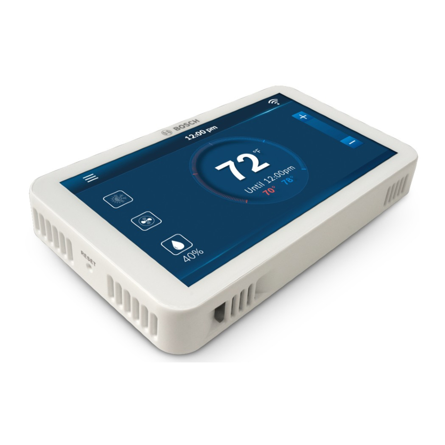
Bosch BCC100, BCC110 Manual
- Installation manual and user's manual (53 pages) ,
- User manual (36 pages) ,
- Quick start manual (31 pages)
Advertisement
Thermostat Features and Functionality
Home Screen Settings
This section is for settings that can be adjusted from the home screen of the thermostat. Clicking on any of the options on the home screen will also take you to the Mode section of the System Settings.
Heating Set Point
This feature establishes the space temperature to be maintained during heating operations. This option is skipped for A/C Equipment.
- Option: 45°F to 99°F
- Default: 68°F
- Click on System Icon at left side of Home screen.

- Select Heat on System Screen.

- Exit System screen (press 'x' in top right corner).
- On Home screen use +/- to Increase/Decrease the heating set point.


Cooling Set Point
This feature establishes the space temperature to be maintained during cooling operations.
- Option: 45°F to 99°F
- Default: 78°F
- Click on System Icon at left side of Home screen.

- Select Cool on System Screen.

- Exit System screen (press 'x' in top right corner).
- On Home screen use +/- to Increase/Decrease the cooling set point.


Auto Heating/Cooling Set Point
This feature establishes the space temperature deadband to be maintained by both heating and cooling operations. Within these setpoints there will be no heating or cooling. The deadband between heating and cooling setpoints cannot be configured less than 5°F.
- Option: 45°F to 99°F
- Cooling Default: 78°F
- Heating Default: 68°F
- Click on System Icon at left side of Home screen.

- Select Auto on System Screen.

- Exit System screen (press 'x' in top right corner).
- On Home screen use +/- to change heating and cooling set points.

- Select Heat or Cool field, and use +/- to Increase/Decrease the set points.


Weather
This section allows the user to view the weather. To access, connect the device to Wi-Fi, go to the menu, and select weather.
Current Weather
This feature provides information on the current weather based on location.
 A connection to Wi-Fi is required, and this information can only be viewed the thermostat is paired with the App and the installation address is provided.
- Main Menu
- Weather
- Select Current


Weather Next 10 Hours
This option provides information on the weather forecast for next 10 hours.
A connection to Wi-Fi is required.
- Main Menu
- Weather
- Select Today


Weather Next 5 Days
This option provides information on the weather forecast for next 5 days.
A connection to Wi-Fi is required.
- Main Menu
- Weather
- Select 5-Days


Schedule
This section allows the user to select and edit a schedule for their system. To access the Schedule section, choose the menu, and select "Schedule". To add and remove schedules, you must use the app.
Available Schedules
This option allows the user to select previously created custom schedules
- Main Menu
- Schedule
- Select a schedule


Edit Schedule
This feature lets the user edit a previously created schedule. Within this section, the user set multiple schedules within a day, copy schedules and delete schedules.
- Main Menu
- Schedule
- Select a Schedule
- Select "Setup"
- Select a day
- Edit start times
- Edit heat and cool temps


Device Settings
The Device Settings are for settings that pertain to the BCC device itself. The user can access the device settings by selecting this section in the menu.
Wi-Fi Select
This section allows the user to select between the available Wi-Fi sources in the area to establish a Wi-Fi connection.
- Main Menu
- Device Settings
- Wi-Fi
- Select the magnifying glass
Use the Up and Down keys to find and select the desired Wi-Fi network.

Wi-Fi Search
This sections allows the user to search for the Wi-Fi source if it does not appear on the list.
- Main Menu
- Device Settings
- Wi-Fi
- Select SSID
Type the name of the desired Wi-Fi network using the keyboard.

Wi-Fi On/Off
This feature allows the user to switch the Wi-Fi on and off from the device.
- Main Menu
- Device Settings
- Wi-Fi
- Select Power OFF


Message
This screen provides the user with alert message from the thermostat. Includes System alerts (e.g. software updates) and Service alerts (e.g. Change Filter).
- Main Menu
- Device Settings
- Messages


Brightness
This feature allows the user to adjust the brightness of the thermostat.
- Options: High, Medium, Low
- Default: High
- Main Menu
- Device Settings
- Screen
- Select Brightness option


Timeout
Allows the user to set the screen time out schedule for the thermostat. If there's no activity within this time the screen goes blank.
- Options: 20sec, 1 min, 3 min
- Default: 1 min
- Main Menu
- Device Settings
- Screen
- Timeout
- Select the timeout option


Screen Lock
Allows the user to set a 4-digit numeric passcode to lock screen. Once set, the BCC will prompt user to re-enter password when trying to access touchscreen of thermostat.
- Options: On/Off
- Default: Off
- Main Menu
- Device Settings
- Screen
- Screen Lock
- Select Screen Lock option


Date Format
Gives the user options to select the date format as per their choice.
- Options: MM/DD/YYYY, DD/MM/YYYY, YYYY/MM/DD
- Default: MM/DD/YY
- Main Menu
- Device Settings
- Date & Time
- Select the Date Format


Time Format
This feature allows the user to select the time format.
- Options: 12hrs and 24hrs
- Default: 12hrs
- Main Menu
- Device Settings
- Date & Time
- Select Time format


Account Information
Provides the user with Account ID, Created Date, and Geo Location. All three fields can be changed by clicking the "Change" button.
- Main Menu
- Device Settings
- Device Information
- Account


System Information
Provides the user information on the thermostat hardware and software including: Model, Software Version, HD version, MAC ID.
- Main Menu
- Device Settings
- Device Information
- System


System Settings
This section allows the user to change settings related to the HVAC system in their building. To access these settings, select menu, and choose "System Settings".
Fan Settings
This section allows the user to select one of three available Fan modes. Auto, On and Circulation.
- Default: Auto
- Main Menu
- System Settings
- Mode
- Fan
Auto
In this mode the fan will only run during heating or cooling operation.
On
In this mode the fan will be continuously on, even if the system mode has been set to Off.

Circulation
This feature gives the user the option to circulate air within the conditioned space. The fan will cycle On and Off depending on the On time and Off time specified in the setup page. User can also choose to set a schedule during which the fan will cycle. If the user chooses no schedule the Fan will continuously cycle.

Humidity Control
This feature allows a user with a properly installed and wired humidifier accessory to choose how the system controls humidity and set the relative humidity set point. Selecting No disables the humidity control function.
- Options: Yes/No; 30% to 90%
- Default: No; 50%
- Main Menu
- System Settings
- Mode
- Select Accessory
- Select Enable Automatic Humidity control
Use the Up and Down keys to select Humidity Level.

Select Degree C or F
This feature establishes the unit for temperature.
- Options: °F or °C
- Default: °F
- Main Menu
- System Settings
- Temperature
- Unit


Low Space Temperature Monitor
This feature establishes the minimum space temperature that will be allowed. If the space temperature falls below the established value, the thermostat will bring on the equipment in heating mode; even if the thermostat's operation mode is set to "OFF". The normal heating cycle as determined by all the User Setup Features will be followed (this includes the staging sequence, minimum run time, and cycle time).
This option is skipped for A/C equipment.
- Options: On/Off; 45°F to 70°F
- Default: Off; 50°F
- Main Menu
- System Settings
- Temperature
- Alert
- Click LOW text box
Use the Up and Down keys to select the Low Stage Temperature.

High Space Temperature Monitor
This feature establishes the maximum space temperature that will be allowed. If the space temperature rises above the established value, the thermostat will bring on the equipment in cooling mode even if the thermostat's operation mode is set to "OFF". The normal cooling cycle as determined by all the User Setup Features will be followed (this includes the staging sequence, minimum run time, and cycle time).
- Options: On/Off; 70°F to 99°F
- Default: Off; 99°F
- Main Menu
- System Settings
- Temperature
- Alerts
- Click HIGH text box
Use the Up and Down keys to select the High Stage Temperature.

Reset Heating and Cooling Runtime
This feature allows the user to reset heating or cooling runtime. Selecting "Yes" will reset the respective runtime to Zero and Starting date to the current date.
- Main Menu
- System Settings
- Run Time
- Reset (Heating or cooling)


Air Filter
This feature allows the ability to establish the number of days of operation of the HVAC equipment between filter changes. The thermostat will send a notification to the user to change the Air Filter of their system based on the set period.
- Options: 15 Days to 360 Days
- Default: 90 days
- Main Menu
- System Settings
- Run Time
- Air Filter
- Select setup
Use the Up and Down keys to adjust the Replacement Time Period.

Water Pad
This feature allows the ability to establish the number of days of operation of the HVAC equipment with humidifier option, between water (evaporator) pad changes. The thermostat will send a notification to the user to change the Water Pad of their system based on the set period.
- Options: 15 Days to 360 Days
- Default: 90 days
- Main Menu
- System Settings
- Run Time
- Water Pad
- Select setup
Use the Up and Down keys to adjust the Replacement Time Period.
The system configuration must have the Humidifier Accessory chosen for this feature to be available.

System Update
This option is used to update the device with the latest firmware version if the automatic update is unsuccessful.
- Main Menu
- System Settings
- System Update
- Download the most recent update


Unit Configuration
This section allows the user to select the configuration of their system. The user can choose between Fossil Fuel, Heat Pump, Dual Fuel, Electric, and no Heating. Once the user is in the System Settings, select Unit Configuration to access this selection.
Compressor Configuration
This feature establishes the number of compressors stages that the equipment is using.
- Options: Fossil Fuel Stage(s) 1 and 2, Air Conditioner Stage(s) 0, 1 and 2
- Default: Heat Pump Stage 2 Electric Stage 2
- Main Menu
- System Settings
- Unit Configuration
- Heat Type
- Stages
Depending on the Heat type chosen, the options available may vary.

Auxiliary Heating
This function allows for an automatic shift from compressor heat to auxiliary heating (e.g. electric heat) when a Heat pump system is used.
This option is only for heat pumps.
Enables additional heating stage if compressor cannot satisfy the current heating set point.
- Options: Enable and Disable
- Default: Enable
- Main Menu
- System Settings
- Unit Configuration
- Heat Type (select Heat Pump)
- Setup
Auxiliary Heating (under Heat Type)

Humidifier Control
This feature enables the use of a humidifier. The setup technician must set the humidity set point to establish the desired humidity level that should be maintained. The humidifier will only be activated during a heating call.
This option is skipped for A/C equipment.
- Options: Humidifier, Dehumidifier and None
- Default: Dehumidifer
- Main Menu
- System Settings
- Unit Configuration
- Accessory
- Select Humidifier


DeHumidification Control
This feature allows the ability to enable cool-to-dehumidify functionality (if the HVAC equipment includes this feature) or to disable the functionality and operate hot gas reheat (if the HVAC equipment is equipped with this feature). When cool-todehumidify functionality is enabled, the cooling equipment will remain on until the humidity set point is met or the over cooling temperature has been reached. The over cooling temperature is the permissible number of degrees below the set point that the user will allow in an attempt to better dehumidify the space.
- Options: Enable and Disable
- Default: Disable
- Main Menu
- System Settings
- Unit Configuration
- Accessory
- Dehumidifier
- Setup


Reversing Valve Energize Method
Based on user selection, this parameter is used to set the reversing valve logic, based on heat pump design, to control the flow of refrigerant.
Selecting cool will energize the reversing valve during cooling operations (O).
Selecting heat will energive the reversing valve during heating operations (B).
- Options: Cool and Heat
- Default: Heat
- Main Menu
- System Settings
- Unit Configuration
- Heat type (Select Heat Pump)
- Select Setup
Advanced Settings
The Advanced Settings are for the specific settings about how the system operates. Here is also where the installer/contractor can access settings not available to the homeowner. The Advanced Settings are accessed by clicking on Menu, then Advanced Settings.
Fan On Delay in Heating
This feature allows the ability to delay the fan motor from energizing for a specified amount of time while in the heating mode.
This option is skipped for A/C equipment.
- Options: 0 Seconds to 120 Seconds.
- Default: 0 Seconds
- Main Menu
- Advanced Settings
- Heating & Cooling
- Enter Professional Access code "1886"
- Fan Delay
- Select On
Use the Up and Down keys to select Fan Delay.

Fan On Delay in Cooling
This feature allows the ability to delay the fan motor from energizing for a specified amount of time while in the cooling mode.
- Options: 0 Seconds to 120 Seconds.
- Default: 0 Seconds
- Main Menu
- Advanced Settings
- Heating & Cooling
- Enter Professional Access code "1886"
- Fan Delay
- Select On
Use the Up and Down keys to select Fan Delay.

Minimum Run Time
This feature establishes the minimum allowable run time for the compressor. The minimum run time prevents short run time and lengthens the life of the compressor. The compressor will continue to run for the specified number of minutes even if the set point is reached.
Minimum run time is the number of seconds the thermostat will call for heating or cooling to ensure a comfortable cycling rate. Setting the System to Off or the opposite system call will override the timer and immediately terminate the heating or cooling call.
The minimum run time (MRT) upper limit is tied to the Stage Delay Timer (SDT) setting (600s or 10min by default). The upper limit for MRT may be set as high as 90 minutes, if the SDT is set accordingly.
- Options: 180 seconds to Stage Delay Timer Setting (600 seconds/10 minutes by default, but can be set up to 90 minutes)
- Default: 300 Seconds
- Main Menu
- Advanced Settings
- Heating & Cooling
- Enter Professional Access code "1886"
- Min. Run Time
Use the Up and Down keys to select the minimum run time.

Anti Short Cycle (ASC) Timer
The minimum off time is the number of seconds after a call and before a new heating or cooling call can be initiated.
- Options: 0 to 300 seconds
- Default: 300 seconds
- Main Menu
- Advanced Settings
- Heating & Cooling
- Enter Professional Access Code "1886"
- Anti Short Cycle
 Timer Setting")
 Timer Setting")
Cycle Time
The minimum off time is the number of seconds after a call and before a new heating or cooling call can be initiated.
- Options: 60 to 300 seconds
- Default: 180 seconds
- Main Menu
- Advanced Settings
- Heating & Cooling
- Enter Professional Access code "1886"
- Cycle Time


Zero Energy Band
This feature establishes the temperature differential at which a heating or cooling call occurs. The room temperature will need to drop by this value from the heating setpoint for a heating call to occur. For cooling, the room temperature will need to be raised by this value.
- Options: 0.5°F to 2°F
- Default: 2°F.
- Main Menu
- Advanced Settings
- Heating & Cooling
- Enter Professional Access code "1886"
- Zero Energy Band
Use the Up and Down keys to select the range.

Latching
This feature establishes how the HVAC Equipment will stage down. If the unit possess multiple stages of heating or cooling, the ability of controlling the stage down process can be beneficial. With this feature disabled, once the set point is met, the thermostat will stage down to the previous stage. After the stage delay, if the set point is still satisfied, the thermostat will stage down once again. With this feature enabled, once the set point has been satisfied, all stages will be turned off and the thermostat will go into standby mode.
- Options: Enable and Disable
- Default: Disable
- Main Menu
- Advanced Settings
- Installer Access
- Enter Professional Access Code "1886"
- Enter Action code "ST"
- Latching


Stage Delay
After the thermostat has been continuously calling for a time equal to the selected time period, the Stage Delay Timer automatically up stages the heating or cooling. The timer will not upstage cooling if the indoor temperature is below the selected temperature. Similarly, it will not upstage heating if the indoor temperature is above the selected temperature. Neither upstaging for cooling or heating will occur if the space temperature is within the Zero Energy Band.
- Options: 3 minutes to 90 minutes.
- Default: 10 min
- Main Menu
- Advanced Settings
- Installer Access
- Enter Professional Access Code "1886"
- Enter Action code "ST"
- Select Stage Delay
Use the Up and Down keys to select the Stage Delay.

Stage Temp
This feature allows the thermostat to determine how quickly it needs to command the next stage of heating based upon the temperature differential.
- Options: 0°F to 15°F
- Default: 4°F
- Main Menu
- Advanced Settings
- Installer Access
- Enter Professional Access Code "1886"
- Enter Action code "ST"
- Select Stage Temp


Factory Reset
This function allows the user to reset the thermostat to initial factory settings.
- Main Menu
- Advanced Settings
- Select Factory Reset
Select "Yes" to confirm Reset or "No" to cancel.

App Features
This section discusses what features the user can control from the mobile app.
Home
View room temperature and adjust set point. Use the buttons at the bottom of the BCC Home tab screen to remotely adjust the System Mode, Fan Mode and Accessory Mode.

- Open app
- Go to BCC Dashboard
![]()
- Adjust Set Point
Add Schedule
Use app to add or select a schedule. Schedule can have a desired time, heat and cool temperature and it will be set as per user's need.

- Open app
- Go to BCC Dashboard
- Select Schedule tab
- Choose a Schedule or Add a new one.
Settings
Use the Settings tab to adjust temperature settings, date & time, location, screen lock, and view device information.

- Open app
- Go to BCC Dashboard
- Select Settings tab
Staging Logic
Staging response determines how the thermostat stages heating or cooling calls based on the difference between space temperature and the set point (1.0°F or 1.5°F).
Staging Timers
There are 4 timers defined in the stage algorithm, MRT (Minimum Run Timer), ASC (Anti-Short Cycle Timer), Stage Delay and a fixed 3 minutes timer for quick staging down.
- When any stage is on, it has to run for the MRT, except in the scenario of quick staging down where the heating/cooling is turned off.
- When any stage is up or down, it has to wait for Stage Delay to expire.
- When all stages are turned off, the system has to wait for ASC to expire before it can be turned on again. Please note, the ASC timers run concurrently with Fan off Delay timer defined elsewhere.
Table 1: Stage Timers
| Interval | Minimum | Maximum | Default | Resolution |
| Stage Delay | 3 Minutes | 90 Minutes | 10 Minutes | 1 Minute |
| MRT(Minimum Run Time) | 3 Minutes | Stage Delay | 5 Minutes | 1 Minute |
| ASC (Anti-Short Cycle) | 0 Minutes | 5 Minutes | 5 Minutes | 1 Minute |
| Quick Stage Down | 3 Minutes | 3 Minutes | 3 Minutes | Fixed |
Staging Temp
Stage temperature is use to determine whether there is a need for quick staging up or staging down based on a temperature setpoint differential.
Table 2: Stage Temp
| Interval | Minimum | Maximum | Default | Resolution |
| Stage Temp | 0°F | 15°F | 4°F | 1°F |
WSHP Fault Codes
If your Bosch Connected Control (BCC) thermostat is connected to one of Bosch's Water Source Heat Pump (WSHP) products, the following WSHP fault codes can be displayed on the BCC. Please refer to the WSHP product's installation and operation manual for more details on troubleshooting.
High Pressure Alarm
The equipment has detected a high head pressure condition and prohibited heating and cooling calls. Contact your local contractor for service. Press the enter key to return to normal thermostat display.
Low Pressure Alarm
The equipment has detected a low head pressure condition and prohibited heating and cooling calls. Contact your local contractor for service. Press the enter key to return to normal thermostat display.
Condenser Coil Freeze Alarm
The equipment has detected a freeze condition and prohibited heating and cooling calls. The sensor that has triggered this fault is monitoring the refrigerant temperature between the TXV and the air coil. The UPM board is aware of the mode of operation, and this sensor will be monitored in the cooling mode. Contact your local contractor for service. Press enter key to return to normal thermostat display.
Condensate Alarm
The equipment has detected a condensate line blockage condition and prohibited cooling calls. Contact your local contractor for service. Press the enter key to return to normal thermostat display.
Brown Out Alarm
The equipment has detected a power brownout condition and prohibited heating and cooling calls. Contact your local contractor for service. Press the enter key to return to normal thermostat display.
Evaporator Coil Freeze Alarm
The equipment has detected a freeze condition and prohibited heating and cooling calls. The sensor that has triggered this fault is monitoring the refrigerant temperature between the TXV and the water coil. The UPM board is aware of the mode of operation, and this sensor will be monitored in the heating mode. Contact your local contractor for service. Press enter key to return to normal thermostat display.
Action Codes
Humidity Calibration (HC)
Ability to adjust humidity readings after extended product use.
- Options: -5% to 5%
- Default: 0%
- Main Menu
- Advanced Settings
- Installer Access
- Enter professional access code "1886"
- Enter action code "HC"
- Use the Up and Down keys to select humidity calibration


Relative Humidity Hysteresis (HSD)
Ability to adjust the set point differential (hysteresis) for the humidity control.
- Options: 3% to 5%
- Default: 5%
- Main Menu
- Advanced Settings
- Installer Access
- Enter professional access code "1886"
- Enter action code "HSD"
- Use the Up and Down keys to select relative humidity hysteresis


Initial Setup (IS)
Ability to access the initial setup process typically only initiated the first time a new unit is powered on, or after a factory reset.
- Main Menu
- Advanced Settings
- Installer Access
- Enter professional access code "1886"
- Enter action code "IS"


Sensor Calibration (SC)
Ability to adjust temperature readings after extended use.
- Options: -10.0 to 10.0
- Default: 0.0
- Main Menu
- Advanced Settings
- Installer Access
- Enter professional access code "1886"
- Enter action code "SC"
- Use the Up and Down keys to select sensor calibration


Sensitivity Level (SS)
Ability to adjust how often the system cycles to maintain the set point(s).
- Options: Level 1 to Level 9
- Default: Level 9
- Main Menu
- Advanced Settings
- Installer Access
- Enter professional access code "1886"
- Enter action code "SS"
- Use the Up and Down keys to select sensitivity level


Staging (ST)
Ability to configure staging settings for Latching, Stage Delay, and Stage Temp.
- Main Menu
- Advanced Settings
- Installer Access
- Enter professional access code "1886"
- Enter action code "ST"


Online Help Resources
Alternatively, please visit our Service & Support webpage to find FAQs, videos, service bulletins, and more; www.boschheatingcooling.com/service or use your cellphone to scan the code below.

United States and Canada
Bosch Thermotechnology Corp.
65 Grove St.
Watertown, MA 02472
![]() Tel: 800-283-3787
Tel: 800-283-3787
www.bosch-homecomfort.us
Documents / Resources
References
Download manual
Here you can download full pdf version of manual, it may contain additional safety instructions, warranty information, FCC rules, etc.
Advertisement


Need help?
Do you have a question about the BCC100 and is the answer not in the manual?
Questions and answers