Advertisement
INTRODUCTION
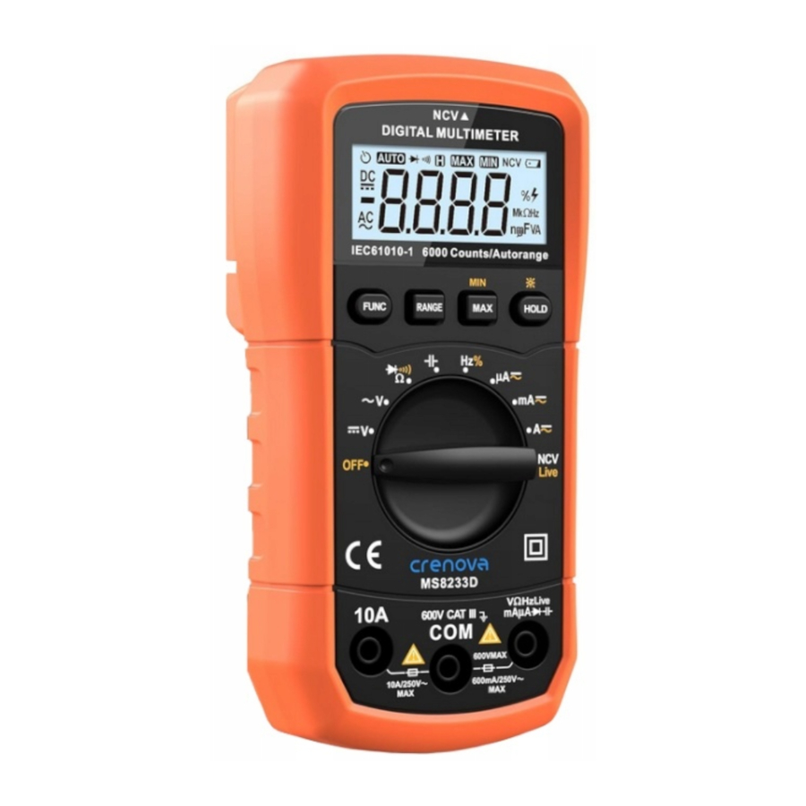
Crenova MS8233D is a reliable multi-function digital multimeter for safe, easy and fast electrical measurements. This high performance handheld multimeter is equipped with a 6000 count LCD display to give clear and accurate readings. It is designed to measure DC/AC voltage, DC/AC current, resistance, capacitance, frequency, duty Cycle, test diode and continuity, and trace live wires. MSB233D also comes with advanced features, such as auto power off, NCV (Non-Contact Voltage) detector, backlight, data hold, and more practical measuring modes and functions. It is an ideal tool for laboratory, school, factory, and home use.
PRODUCT OVERVIEW
Technical Specifications
Model: MSB233D
LCD Digital Display: 6000 counts (3 5/6), auto polarity indication
Sampling Rate: approx. 3 times per second
Measuring Technology: A/D converter
Over Range Indication: "OL" appears on the screen
Low Battery Indication: " " appears on the screen
Operating Environment: 0º C to 40º C, relative humidity < 75%
Storage Environment: -20º C to 60º C, relative humidity 85%
Power Supply: 2 x 1.5V AAA batteries
Fuse Type:
fuse FSI for mAuA input terminal: ( 5 x 20)mm, 600mA, 250V
fuse FS2 for I10 input terminal: (5 x 20)mm, 10A, 250V
Size: 147mm x 74mm x 42mm
Weight: approx. 210g (batteries are included)
Box Contents:
| Crenova MS8233D Digital Multimeter (1 piece) | probe est Leads 1 pair) |
| Alligator Clip Test Leads (1 pair) | 1.5VAAA Batteries (2 pieces) |
| Carrying Box (1 piece) | user Manual (1 piece) |
Product Description

- 6000 Count LCD display
- Function selection button ("FUNC")
- "RANGE" button
- "MAX/MIN" button
- Data hold/Backlight button ("HOLD/
![]() ")
") - Function selection switch
- "10A" input terminal
- "COW jack
- "V/
![]() /Hz/Live/mA/uA/
/Hz/Live/mA/uA/![]() /
/![]() " input terminal
" input terminal - NCV sensing area
 ")
") /Hz/Live/mA/uA/
 /
/ " input terminal
Display

 | Auto Power Off |  | Minimum Value |
 | DC Measurement |  | Maximum Value |
 | AC Measurement |  | Low Battery |
 | Auto Range |  | Duty Cycle, High voltage |
 | Diode/Continuity Test |  | Resistance/Frequency units |
 | Data Hold |  | Capacitance/Voltage/Current Units |
 | NCV (Non Contact AC Voltage Measurement) | ||
Function Buttons
- Function selection button ("FUNC")
Rotate the function selection switch to desired setting, short press this button to select:- Resistance, diode Or continuity mode,
- Frequency or duty cycle mode,
- DC or AC current mode,
- NCV or Live detector mode, according to your needs.
When measuring AC voltage or AC current, you can also short press this button to quick measure the frequency. After the Meter is auto powered off, short press this button to wake it up. To turn off the APO (auto power off) function, long press this button and rotate the switch to turn on the Meter.
- "RANGE" button
After rotating the switch to desired setting (the Meter is powered on), short press once to enter manual range mode. You can short press this button few times to change the range until it meets your demands. Long press to exit manual range mode (the Meter is back to auto range mode). - "MAX/MIN" button
After the Meter is powered on, short press this button to show maximum value. Press it again to show minimum value. Long press to exit.
Note: The Meter will stay in the same measurement function/mode/range when the screen displayed maximum or minimum value. - Data hold/ Backlight button ("HOLD/
![]() ")
")
Short press to turn on/off data hold (disp ay hold) mode,![]() will appear on the screen when the mode is turned on. Long press to power on/off backlight, the backlight will automatically turn off after 15 seconds.
will appear on the screen when the mode is turned on. Long press to power on/off backlight, the backlight will automatically turn off after 15 seconds.
 will appear on the screen when the mode is turned on. Long press to power on/off backlight, the backlight will automatically turn off after 15 seconds.
To prevent possible electric shock, fire, or personal injury, do not use data hold mode to determine if a circuit is live or measure unknown voltage in a circuit. When data hold mode is turned on, the LCD screen will keep original data even you measure a different voltage.
OPERATING INSTRUCTIONS
Always check the battery status before using the Meter, select the correct measurement function/range/mode. If the Meter is out of power, " " will appear on the display. Please kindly note the sign
  beside the terminals, it warns that test voltage and current cannot exceed the specified value in this manual or on the product.
DC/AC Voltage Measurement
- According to your actual requirements, rotate the function selection switch to DC voltage or AC voltage setting.
- Insert the black test lead into "COM" jack and red test lead into "
![]() " jack.
" jack. - Connect the Meter in parallel with the circuit using test leads.
- Read measurement results on the display.
 " jack.
 Note:
Note:

- DO not measure the voltage over 600V, it will cause personal injury and Meter damage.
- If "OL" shows on the screen, it means "over range".
- When finished, remove the test leads from the tested circuit and the Meter.
- When measuring a high voltage (above DC/AC 30V), high voltage symbol shows on the screen, use personal protective equipment to prevent shock and arc blast injury where hazardous live conductors are exposed.
DC/AC Current Measurement
- Rotate the function selection switch to PA, mA, or A (current) setting.
- Short press the "FUNC" button to choose DC or AC current mode.
- Insert the black test lead into "COM" jack, and the red test lead into "10A" jack (max. 10A) or " " jack (max. 600mA).
- Connect the Meter in-series in the circuit using the test leads. 2.5 Read measurement results on the display.
Note:

- DO not use the current jack to measure a voltage
- Before measuring the current, you should turn off the circuit power, and check if the input terminal and range/mode function are correct. TO measure an unknown current, switch to A (current) setting and use "10A" jack first, then change the setting and jack if needed.
- Overload input or wrong operation will blow the fuse. To protect the Meter and user, measuring time shall not exceed 10 seconds, and please al ow the Meter to recover for more than 15 minutes before the next measurement.
Resistance Measurement

- Rotate the function selection switch to "
![]() " (resistance) setting, connect the test leads across the tested resistance.
" (resistance) setting, connect the test leads across the tested resistance. - Insert the black test lead into "COM" jack, and the red test lead into "
![]() " jack.
" jack. - Read measurement results on the display.
 " jack.
Note:
- TO avoid electric shock, injury, Or damage to the Meter, disconnect circuit power and discharge al high-voltage capacitors before testing resistance.
- When the test leads are not connected across a resistor, or when a failed resistor is under test, the display will indicate "OL"
- For low resistance measurement, the resistance of test leads is from 0.1
![]() to 0.3
to 0.3![]() , it may bring errors. Please subtract test lead resistance from the actual resistance to get an accurate reading.
, it may bring errors. Please subtract test lead resistance from the actual resistance to get an accurate reading. - When tested resistance is more than 1M
![]() , the Meter will take few seconds to obtain the accurate reading. t is normal for high resistance measurement.
, the Meter will take few seconds to obtain the accurate reading. t is normal for high resistance measurement. - Do not input voltage when measuring the resistance.
Capacitance Measurement

- Rotate the function selection switch to "
![]() " (capacitance) setting, connect the test leads to the tested capacitor. Make sure the polarity of the red test lead is "+".
" (capacitance) setting, connect the test leads to the tested capacitor. Make sure the polarity of the red test lead is "+". - Connect the black test lead to "COM" jack and the red test lead to "
![]() " jack.
" jack. - Read measurement results on the display.
 " (capacitance) setting, connect the test leads to the tested capacitor. Make sure the polarity of the red test lead is "+".
Note:
- If "OL" shows on the screen, it means "over range".
- When measuring the capacitance less than 20nF, the Meter may display a residual reading. It caused by the distributed capacitance of test leads. The residual reading should be subtracted from the measurement result to get an accurate value.
- Capacitor leakage or breakdown will lead to unstable readings on the screen. When measuring large capacitance, the Meter will also take few seconds to stabilize. It is normal for large capacitance measurement.
- To avoid electric shock, injury, or damage to the Meter, disconnect circuit power and discharge all high-voltage capacitors before testing capacitance.
Diode and Continuity Test

- Rotate the function selection switch to resistance/diode/continuity setting, short press the "FUNC" button to select diode or continuity mode. ( Resistance is the default mode in this setting.)
- Insert the black test lead into "COM" jack and the red one into "
![]() " jack.
" jack. - Connect the test leads to the tested diode, make sure the polarity of the red test lead is "+", the black test lead is " When the reading is a close approximation of positive voltage drop of the diode, it indicates forward bias. "OL" on the screen indicates reverse bias.
- For continuity test, connect the test leads to the circuit to be tested. If the resistance is less than around 50 ± 20
![]() , the buzzer beeps.
, the buzzer beeps.
 " jack.
Note:
- To avoid electric shock, injury, or damage to the Meter, disconnect circuit power and discharge al high-voltage capacitors before diode and continuity test.
- In diode setting, the Meter can measure the voltage drop of a diode and its PN junction. For a properly constructed silicon semiconductor, the reading of forward voltage drop should be between 0.5V and 0.8V,the reverse voltage drop shows "OL" on the screen (refers to open circuit). It means the polarity Of the black test lead is "+", the red test lead is ""-"
Frequency and Duty Cycle Measurement

- Rotate the function selection switch to frequency/duty cycle setting, and connect the test leads or shield cable across the signal source or circuit load to be tested.
- Connect the black test lead to "COM" jack and the red lead to "
![]() " jack.
" jack. - Short press the "FUNC" button to select frequency or duty cycle mode.
- Read measurement results on the display.
 " jack.
Note:
- For frequency measurement, the measuring range of input voltage is listed below:
10Hz - 100kHz: 1V rms![]() input voltage
input voltage ![]() 20V rms,
20V rms,
100kHz - 10MHz: 3V rms![]() input voltage
input voltage ![]() 20V rms.
20V rms. - For duty cycle measurement:
10% - 90%, suitable for 10Hz - 1kHz square wave,
30% - 70%, suitable for 1kHz - 10kHz square wave,
3V pp![]() input voltage
input voltage![]() 20V pp.
20V pp.
When measuring the frequency, do not input voltage that is greater than 20V rms to avoid injury - When finished, remove the test leads from the tested circuit and the Meter.
Non-Contact Voltage (NCV) Detector

- Rotate the function selection switch to NCV/ ive setting.
- The voltage range can be detected is from 48V to 220V, place the top of the Meter (NCV sensing area) close to the AC power line to be tested. When AC voltage is detected, the buzzer beeps. The stronger the AC voltage is detected, the faster the buzzer beeps.
Live Wire Detector

- Rotate the function selection switch to NCV/Live setting.
- Short press the "FUNC" button to select Live detector mode.
- Insert the red test lead into "
![]() " jack, and contact the measured point using the red test ead.
" jack, and contact the measured point using the red test ead. - If the backlight flashes and the buzzer beeps, the measured line is live wire. If nothing changes, the measured line contacted by the red test ead is not live wire.
 " jack, and contact the measured point using the red test ead.
Note:
- Follow al safety rules when testing a live wire.
- This function is only designed to detect standard AC mains power lines (AC 110V - 380V).
Auto Power Off (APO)
To save battery power and extend service life, APO function is already set by default when you turn on the Meter. It will automatically power off in 14 minutes without any operation. Before shutdown, the Meter gives 3 short beeps first, and then a long beep if still no further operation. To turn off the APO function, long press the "FUNC" button and rotate the switch to turn on the Meter. The APO function will reactivate after you switching on the Meter next time.
ELECTRICAL SPECIFICATIONS
Accuracy is specified for 1 year after calibration, at operating temperatures Of 18ºC to 28ºC, with relative humidity at 0% to 75%. Accuracy specifications take the form of: ± ( [% of Reading] + [Counts] )
DC Voltage
| Range | Accuracy | Resolution | Input Impedance | Overload Protection |
| 600mV |  (0.5%+7) (0.5%+7) | 0.1mV |  10M 10M | 250V DC/AC rms |
| 6V | 0.001V | |||
| 60V | 0.01V | |||
| 600V | 0.1V |
AC Voltage (True RMS)
| Range | Accuracy | Resolution | Input Impedance | Overload protection |
| 6V | ± (1.0% + 10) | 0.001V | 10M | 250V DC/AC rms |
| 60V | 0.01V | |||
| 600V | ± (1.0% +12) | 0.1V |
Accurate measurement range: 10% to 100% of range
Frequency response: 40Hz 1kHz
Measuring method (sine wave): True rms
Crest factor: CF 3, when CF 2 2, increases additional error of 1% of the reading
DC Current
| Range | Accuracy | Resolution | Overload protection |
600 A A | ± (1.0% + 10) | 0.1A | 600mA/250V |
| 6000A | 1A | ||
| 60mA | ± (1.2% + 8) | 0.01 mA | |
| 600mA | 0.1mA | ||
| 6A | ± (1.2% + 10) | 0.001A | 10A/250V |
| 10A | 0.01A |
Maximum input current: 10A (Measuring time: 10 seconds, Recovery time: 15 minutes)
AC Current (True RMS)
| Range | Accuracy | Resolution | Overload Protection |
| 600A | ± (1.5% + 10) | 0.1A | 600mA/250V |
| 6000A | 1A | ||
| 60 mA | 0.01mA | ||
| 600mA | 0.1mA | ||
| 6A |  (2.0% +5) (2.0% +5) | 0.001A | 10A/250V |
| 10A | 0.01A |
Accurate measurement range: 10% to 100% Of range
Frequency response: 40Hz - 1kHz
Measuring method (sine wave): True rms
Crest factor: CF 3, when CF 2, increases additional error of 1% of the reading
Maximum input current: 10A (Measuring time: 10 seconds, Recovery time: 15 minutes)
Resistance
| Range | Accuracy | Resolution | Short Circuit Current | Open Circuit Voltage | Overload Protection |
| 600 | (0.8% +5) | 0.1 | 255.5A | Around 1V | 250V DC/AC rms |
| 6k | (0.8%+4) | 0.001k | 255.5A | ||
| 60k | 0.01k | 76.6A | |||
| 600k | 0.1k | 9.4A | |||
| 6M | 0.001M | 1.0A | |||
| 60M | ± (1.2% +10) | 0.01M | 0.1A | Around 0.5V |
Capacitance
| Range | Accuracy | Resolution | Overload protection |
| 6nF | ± (5.0% * 40) | 0.001nF | 250V DC/AC rms |
| 60nF | (3.5% + 20) | 0.01nF | |
| 600nF | 0.1nF | ||
| 6F | 0.001F | ||
| 60F | 0.01F | ||
| 600F | 0.1F | ||
| 6mF | (5.0% +10) | 0.001mF | |
| 20mF | 0.01mF |
Accurate measurement range: 10% to 100% of range
Response time of large capacitor ( 1mF): Approx. 8 seconds
Measurement error does not include the resistance of the lead wires.
Diode and Continuity
| Range | Displayed Value | Test Condition | Protection |
 | Forward voltage drop of the diode | DC Forward current around 1.5mA, open circuit voltage around 3.9V | 25OV DC/AC rms |
| If tested resistance is ess than around 5020 , the buzzer beeps | Open circuit voltage is around 2V |
Do not input voltage when testing diode or continuity!
Frequency and Duty Cycle
| Range | Accuracy | Resolution | Overload Protection |
| 10Hz - 10MHz | (0.3%+3) | 0.01Hz - 1kHz | 250V DC/AC |
| 10% - 90% | 0.1% |
For frequency measurement, input voltage range:
10Hz - 100kHz: 1V rms input voltage 20V rms.
100kHz - 10MHz: 3V rms input voltage 20V rms
For duty cycle measurement:
10% - 90%, suitable for 10Hz - 1kHz square wave,
30% - 70%, suitable for 1kHz - 10kHz square wave,
3V pp input voltage 20V pp
BATTERIES REPLACEMENT
When " " appears on the display, fol ow the steps below to replace the batteries:
- Disconnect test leads from the circuit, rotate the function selection switch to "OFF", and remove the test leads from the terminals.
- Use a screwdriver to remove the screw from the case bottom and lift the battery door.
- Remove the batteries and load the new ones.
- Close the battery door and secure it with the screw.
Note:
- Battery Type: 2 x 1.5V AAA batteries
- use only specified battery in this manual Or on the Meter for replacement.
- Be sure to change the batteries in time, or it will affect measurement accuracy.

MAINTENANCE
- Never disassemble the Meter or change the inner circuit.
- Keep the Meter away from water and dust.
- Wipe the case with a damp cloth and mi d detergent. Do not use abrasives or solvents.
- Remove the batteries when the Meter is not in use for a long period.
TROUBLESHOOTING
If the Meter does not work properly, please read the table below:
| Problem Description | Solution |
No reading on the LCD display |
|
| "" appears on the screen | Replace the batteries |
No current input | Replace the fuse |
Big measurement error | Replace the batteries |
Backlight is not bright | Replace the batteries |
If your problems or inquiries cannot be eliminated after reading the table, please fee free to contact us.
SAFETY NOTES
The Meter conforms to IEC61010-1 CAT 1600V safety standard. To prevent electric shock, fire, personal injury or property damage, please read all safety information and all instructions carefully before you use the Meter.
- Do not use the Meter with damaged housing, rubber holster, terminals, probes, test leads, and accessories or after the Meter malfunctions or is dropped or damaged in any manner, please contact our customer service for a replacement.
- Before measuring voltage higher than 36V DC or 25V rms AC, check the connection and insulation of test leads to avoid electric shock.
- Limit operation to the specified measurement category, voltage, or amperage ratings. Do not apply more than the rated voltage, between the terminals or between each terminal and earth ground.
- Use the correct terminals, function, and range for measurements. Do not change the range when testing the circuit.
- Always use probes, test leads, and accessories, that have the same measurement category, voltage, and amperage ratings as the Meter.
- Remove test leads from the Meter before changing function mode or range. Do not touch the metal probe when testing the circuit.
- To avoid electric shock, injury, or damage to the Meter, disconnect circuit power and discharge all high-voltage capacitors before testing resistance, continuity, diodes, or capacitance.
- Turn off the power and remove test leads from the Meter before replacing the batteries or fuse. Install the batteries and lock the battery door before operating the Meter.
- Always adhere to local and national safety codes. Use personal protective equipment (such as rubber insulating gloves, goggles, flame-resistant protective clothing etc.) to prevent shock and arc blast injury where hazardous ive conductors are exposed.
- Do not use the Meter around explosive gas, vapor, or in damp or wet environments.
- Do not expose the Meter to magnetic fields, extreme heat, or expose to direct sunlight for long periods of time.
Safety and Electrical Symbols
 |  HIGH VOLTAGE! Risk of Electric Shock. | |  Refer to Instruction Manual. |
 | Earth |  | Double Insulation |
 | LOW Battery |  | DC and AC (Direct and Alternating Current) |
 | DC (Direct Current) |  | AC (Alternating Current) |
 | Fuse |  | Conform to European Union Directives. |
Contact us:
- Email (Recommended): support@crenova.net
- Call (Currently only available in English):
USA: +1 (323) 250-0585
UK: +44 20 3287 2598
Documents / ResourcesDownload manual
Here you can download full pdf version of manual, it may contain additional safety instructions, warranty information, FCC rules, etc.
Advertisement


Need help?
Do you have a question about the MS8233D and is the answer not in the manual?
Questions and answers