Epson TM-T88V - Label Printer Manual
- Technical reference manual (158 pages) ,
- User manual (122 pages) ,
- Development manual (30 pages)
Advertisement
- 1 Caution Labels
- 2 Restriction of Use
- 3 Unpacking
- 4 Part Names
- 5 Installing the Printer Horizontally or Vertically
- 6 Setting Up the Printer
- 7 Connecting the Cables
- 8 Attaching the Connector Cover
- 9 Installing Roll Paper
- 10 Attaching the Power Switch Cover
- 11 Troubleshooting
- 12 Removing Jammed Paper
- 13 Cleaning the Thermal Head
- 14 Setting the DIP Switches
- 15 DIP Switch Tables
- 16 Specifications
- 17 Safety Precautions
- 18 Documents / Resources

This is a Class A product. In a domestic environment this product may cause radio interference in which case the user may be required to take adequate measures.
Caution Labels


Do not touch the thermal head and the frame on its side because it can be very hot after printing.
Touching the manual cutter may cause injury.
Restriction of Use
When this product is used for applications requiring high reliability/safety such as transportation devices related to aviation, rail, marine, automotive etc.; disaster prevention devices; various safety devices etc.; or functional/precision devices etc., you should use this product only after giving consideration to including failsafes and redundancies into your design to maintain safety and total system reliability. Because this product was not intended for use in applications requiring extremely high reliability/safety such as aerospace equipment, main communication equipment, nuclear power control equipment, or medical equipment related to direct medical care etc., please make your own judgment on this product's suitability after a full evaluation.
Unpacking
The following items are included with the standard specification printer. If any item is damaged, contact your dealer.
- Printer
- Roll Paper
- Connector cover
- Power switch cover
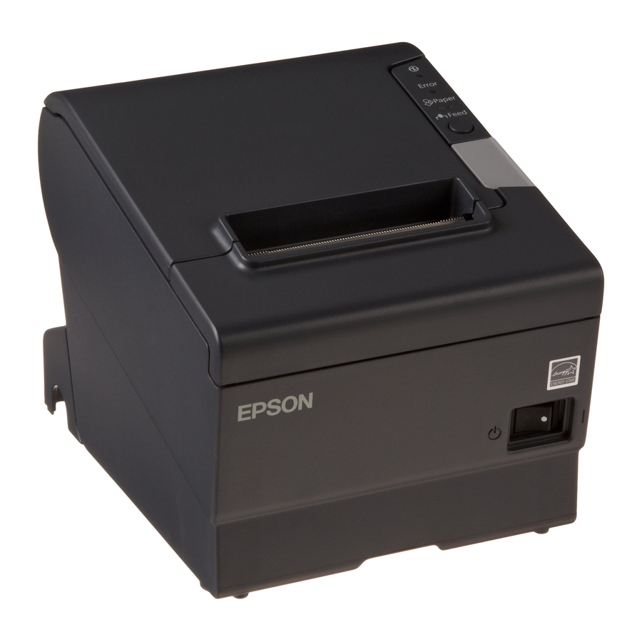
Part Names

Control Panel
![]() (Power) LED
(Power) LED
This LED is on when the printer is on.
Error LED
This indicates an error.
Paper LED
On indicates a paper near end or out. Flashing indicates standby.
Feed button
This button feeds paper.
Installing the Printer Horizontally or Vertically
You can install the printer horizontally on a flat surface (with the paper exit on top) or vertically (with the paper exit at the front) by hanging it on a wall, using the optional WH-10 hanging bracket set.
When hanging the printer on the wall with the hanging bracket set, be sure to attach a connector cover to the printer.
Setting Up the Printer
To set up the printer, follow the steps below.
- Connect the cables.
- Attach the connector cover.
- Install the roll paper.
Connecting the Cables
Do not turn on the printer before installing the printer driver.
- Connect the power cord and USB plus power cable to the connectors on the printer back.

- Connect the interface cable to the computer.
- Insert the power cord plug into a socket.

Attaching the Connector Cover
Follow the steps below to attach the connector cover to protect the cables.
- Turn over the printer.
- Position the two hooks on both sides of the connector cover so that they hook the printer case.

- Push the connector cover down to click onto the printer case.
- Pass each cable through the cable exits at the bottom of the connector cover.
- Turn over the printer, and make sure the cables are not pinched.

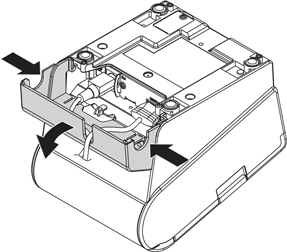
To remove the connector cover, turn the printer over, and push the connector cover down while pushing both sides of the connector cover inward to detach the hooks from the printer case.
Installing Roll Paper
Follow the steps below to install the roll paper.
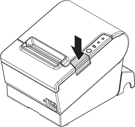
- Press the cover open button to open the roll paper cover.
![]()
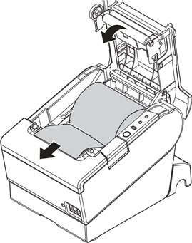
- Remove the used roll paper core if any, and insert the roll paper. The correct direction of the paper is shown in the illustration below.

- Pull out some paper, and close the roll paper cover.
![]()
- Tear off the paper.
![]()

Attaching the Power Switch Cover
The enclosed power switch cover ensures that the power switch is not pressed accidentally. To use this cover, install it as shown in the illustration below.
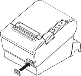
If an accident occurs with the power switch cover attached, unplug the power cord immediately. Continued use may cause fire or shock.
Troubleshooting
No lights on the control panel
Check whether the power supply cable is correctly connected to the printer and the socket.
Error LED on with no printing
- Check whether the roll paper cover is closed. If it is open, close it.
- If the Paper LED is on, check whether the roll paper is correctly installed and any roll paper remains.
Error LED flashing with no printing
- Check whether a paper jam has occurred. If paper is jammed, remove the jammed paper referring to the description below and install the roll paper correctly.
- Printing stops if the head overheats and resumes automatically when it cools.
- For other cases, turn the printer off, and after 10 seconds, back on.
Removing Jammed Paper
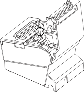
When a paper jam occurs, never pull out the paper forcibly. Open the roll paper cover and remove the jammed paper.
Do not touch the thermal head and the frame on its side (indicated in the circle in the illustration below) because it can be very hot after printing.
If the roll paper cover does not open, follow the steps below.
- Turn off the printer.
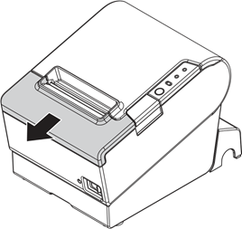
- Slide the cutter cover toward front to open it.
![]()
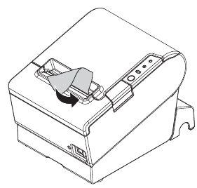
- Turn the knob until you see a triangle in the opening. This returns the cutter blade to the normal position. There is a label near the cutter to assist you.

- Close the cutter cover.
- Open the roll paper cover and remove the jammed paper.

Cleaning the Thermal Head
After printing, the thermal head and the frame on its side (indicated in the circle in illustration below) can be very hot. Be careful not to touch it and to let it cool before you clean it. Do not damage the thermal head by touching it with your fingers or any hard object.
Turn off the printer, open the roll paper cover, and clean the thermal elements of the thermal head with a cotton swab moistened with an alcohol solvent (ethanol or IPA).
Epson recommends cleaning the thermal head periodically (generally every 3 months) to maintain receipt print quality.

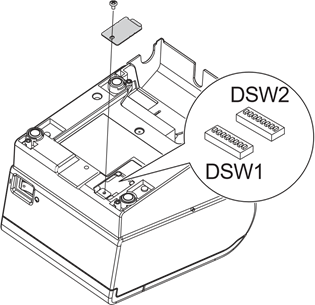
Setting the DIP Switches
Be sure to turn off the printer before removing the cover of the DIP switches. Removing it while the printer is turned on may cause problems such as an electric short, which leads to a malfunction of the printer.
- Turn off the printer.
- Turn over the printer.
- Remove the DIP switch cover by removing the screw.
![]()
- Set the DIP switches using a fine-tipped tool.
- Replace the DIP switch cover, and fix it by installing the screw.
The new setting becomes effective after the printer is turned on.
DIP Switch Tables
DIP switch 1
| SW | Function | ON | OFF |
| 1-1 | Auto line feed | Always enabled | Always disabled |
| 1-2 | Receive buffer capacity | 45 bytes | 4K bytes |
| 1-3~ 1-7 | Undefined | ||
| 1-8 | Power saving function | Disabled | Enabled |
Table A
| Print density/low power | SW2-3 | SW2-4 |
| Print density "Normal" | OFF | OFF |
| Print density "Medium" | ON | OFF |
| Print density "Dark" | OFF | ON |
| Do not set | ON | ON |
DIP switch 2
| SW | Function | ON | OFF |
| 2-1 | Handshaking (BUSY condition) | Receive buffer full | Offline or Receive buffer full |
| 2-2 | Do not change settings | Fixed to OFF | |
| 2-3 2-4 | Print density | See Table A | |
| 2-5 | Release condition of receive buffer BUSY (If receive buffer capacity set to 4 K bytes.) | Releases BUSY when remaining receive buffer capacity reaches 138 bytes. | Releases BUSY when remaining receive buffer capacity reaches 256 bytes. |
| 2-6 2-7 | Do not change settings | Fixed to OFF | |
| 2-8 | Do not change | Fixed to ON | |
Specifications
| Printing method | Thermal line printing | ||
| Dot density | 180 dpi ×180 dpi [dots per 25.4 mm {1"}] | ||
| Printing direction | Unidirectional with friction feed | ||
| Printing width | 72 mm {2.83"}, 512 dot positions | ||
| Characters per line (default) | Font A: 42; Font B: 56 | ||
| Character spacing (default) | Font A: 0.28 mm {.01"} (2 dots), Font B: 0.28 mm {.01"} (2 dots) | ||
| Character size | Standard/Double-height/Double-width/Double-width and Double-height Font A: 1.41 × 3.39/1.41 × 6.77/2.82 × 3.39/2.82 × 6.77 mm Font B: 0.99 × 2.40/0.99 × 4.80/1.98 × 2.40/1.98 × 4.80 mm | ||
| Character structure | Font A (default): 12 × 24; Font B: 9 × 17 (including 2-dot horizontal spacing) | ||
| Number of characters | Alphanumeric characters: 95; International character sets: 18 sets Extended graphics: 128 × 43 pages (including user defined page) | ||
| Printing speed | 300 mm/s {11.8"/s} max.; 70.9 lps (4.23 mm {1/6"} feed) Ladder bar code and 2D code: 100mm/s {2.4"/s} | ||
| The above speed values are approximate. The values are when the printer prints with density "Normal" at 24 V and 25°C {77°F} Speed is adjusted automatically depending on the voltage applied and head temperature. | |||
| Paper feed speed | Approx. 200 mm/s {approx. 7.9"/s} (continuous paper feed with the Feed button.) | ||
| Line spacing (default) | 4.23 mm {1/6"} | ||
| Roll paper (single-ply) | Width | 79.5 mm ± 0.5 mm {3.13" ± 0.02"} | |
| Diameter | Maximum outside diameter: 83 mm {3.27"} | ||
| Spool | Spool diameter: Inside: 12 mm {0.47"}; Outside: 18 mm {0.71"} | ||
| Thermal paper type | NTP080-80 | ||
| Interface | USB Plus Power (Full speed) | ||
| Receive buffer | 4K bytes/45 bytes | ||
| Cash drawer function | 2 drives | ||
| Supply voltage | DC + 24 V ± 7% *Power supply should be 240 VA or less. | ||
| Current consumption | Mean: Approx. 1.8A | ||
| Temperature | Operating: | 5 to 45°C {41 to 113°F} | |
| Storage: | –10 to 50°C {14 to 122°F}, except for paper | ||
| Humidity | Operating: | 10 to 90% RH | |
| Storage: | 10 to 90% RH, except for paper | ||
| Overall dimensions | 148 × 145 × 195 mm {5.83 × 5.71 × 7.68"} (H × W × D) | ||
| Weight (mass) | Approx. 1.6 kg {3.5 lb} | ||
lps: lines per second
dpi: dots per 25.4 mm (dots per inch)
Safety Precautions
This section presents important information intended to ensure safe and effective use of this product. Please read this section carefully and store it in an accessible location.
Shut down your equipment immediately if it produces smoke, a strange odor, or unusual noise. Continued use may lead to fire. Immediately unplug the equipment and contact your dealer or a Seiko Epson service center for advice.
Never attempt to repair this product yourself. Improper repair work can be dangerous.
Never disassemble or modify this product. Tampering with this product may result in injury or fire.
Be sure to use the specified power source. Connection to an improper power source may cause fire.
Do not allow foreign matter to fall into the equipment. Penetration by foreign objects may lead to fire.
If water or other liquid spills into this equipment, unplug the power cord immediately, and then contact your dealer or a Seiko Epson service center for advice. Continued usage may lead to fire.
If you open the DIP switch cover, be sure to close the cover and tighten the screw after adjusting the DIP switch. Using this product with the cover open may cause fire or electric shock.
Do not use aerosol sprayers containing flammable gas inside or around this product. Doing so may cause fire.
Do not connect cables in ways other than those mentioned in this manual. Different connections may cause equipment damage and burning.
Be sure to set this equipment on a firm, stable, horizontal surface. The product may break or cause injury if it falls.
Do not use in locations subject to high humidity or dust levels. Excessive humidity and dust may cause equipment damage or fire.
Do not place heavy objects on top of this product. Never stand or lean on this product. Equipment may fall or collapse, causing breakage and possible injury.
To ensure safety, unplug this product before leaving it unused for an extended period.
Take care not to injure your fingers on the manual cutter
- When you remove printed paper
- When you perform other operations such as loading/replacing roll paper
Documents / ResourcesDownload manual
Here you can download full pdf version of manual, it may contain additional safety instructions, warranty information, FCC rules, etc.
Advertisement


Need help?
Do you have a question about the TM-T88V and is the answer not in the manual?
Questions and answers