Fox 985-62-008, 985-62-009 - COIL-OVER SNAP RING IFP, PERFORMANCE Series Manual
- Installation manual (11 pages)
Advertisement
985-62-008: 15-20 Ford F-150 2WD, Front C/O, Snap Ring, PS, 2.0, IFP, 5.4", 0-2" Lift
985-62-009: 15-20 Ford F-150 4WD, Front C/O, Snap Ring, PS, 2.0, IFP, 5.7", 0-2" Lift
BOX CONTENT
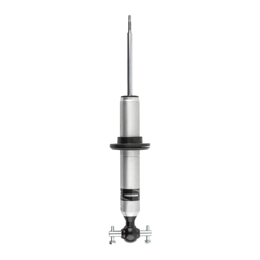
- Performance Series Snap Ring Coil-Over Shock
- Molded Spring Seat
- Aluminum Spring Retainer
- Installation Manual
- FOX Sticker
INSTALLATION GUIDELINES

- Always use a chassis lift for the installation of shocks, and make certain that the raised vehicle is securely attached to the lift to prevent the vehicle from slipping, falling, or moving during the installation process.
- DO NOT install any FOX product without the necessary special tools, expertise and chassis lift or you will subject yourself to the risk of SERIOUS INJURY or DEATH. If you elect to not use a chassis lift (which may result in SERIOUS INJURY or DEATH), ensure that the vehicle is:
- on level ground,
- that all tires on the ground during installation are blocked to prevent vehicle movement,
- that at least two tires are on the ground at all times,
- and that adequately secured jack stands are used to support the vehicle.
NEVER get under the vehicle until you have checked to ensure that the vehicle will be stable during installation.
- FOX direct-replacement shocks are designed to fit your vehicle's shock mounts without modification except the reservoir placement on specific models and applications.
- If a preload adjustment is necessary for your application DO NOT adjust preload with the coil-over on the vehicle. Remove the coil-over from the vehicle and use a spring compressor to remove the spring hardware and spring.
Once the spring is removed, you can adjust the spring seat height by removing and installing the snap-ring. IT IS HIGHLY RECOMMENDED TO USE A SPRING COMPRESSOR WHEN MAKING ANY TYPE OF PRELOAD ADJUSTMENT!
PRODUCT INSTALLATION INSTRUCTIONS
- Please read the installation guidelines for instructions on how to properly lift and secure the vehicle.
- Remove both front wheels.
- Remove OEM coil-over:
- Disconnect sway bar link from lower control arm on left and right sides of the vehicle. Retain OEM hardware (Figure 1).
![]()
- Disconnect upper arm ball joint from spindle (Figure 2).
![]()
- Disconnect sway bar link from lower control arm on left and right sides of the vehicle. Retain OEM hardware (Figure 1).


Upper control arm will likely spring upwards when disconnected.
TIP: Suspension may be compressed upwards with the help of an additional jack to minimize upwards spring-back of the upper control arm. Mallet may free up ball joint / spindle connection. Secure spindle with bungee or rope to prevent stress on sensor wires and break hose. Retain OEM hardware for reuse.
- Disconnect steering linkage from spindle by loosening the ball joint nut (Figure 2).
Swing the steering link out of the way. - Remove nuts fastening the shock's top-mount from the frame (Figure 3).
TIP: Leave one nut loose but hand tight to keep the shock from falling in the following steps.
![]()
- Remove the two nuts fastening the lower shock connection to the lower control arm.

Monitor tension on brake line and sensor bracket. Push lower control arm down and relocate lower shock end such that the shock can be removed (Figure 4).

- Relieve the force on the lower control arm. Finish removing the remaining top-mount nut while holding the shock as it will likely drop once the nut is removed. Shock should be free for removal.
Use care not to damage the drive shaft boot (4WD models).
- Disassembly of OEM shock assembly:
- Make clear notes on alignment of Top mount/spring to lower control arm connection.
TIP: In addition to notes taking a picture with cellular phone may be helpful. Paint pen marking between spring and top-mount is another good idea. This is needed for build up of the FOX shock. - Use a professional spring compressor to compress shock assembly according to its included instructions (Figure 3).
- Make clear notes on alignment of Top mount/spring to lower control arm connection.
Follow all safety guidelines provided by the spring compressor manufacturer.
Using a spring compressor in an unsafe manner can lead to SERIOUS INJURY or DEATH.
- Center nut in top mount is removed allowing shock to be removed from spring and associated hardware (Figure 5). Refer to OEM service manual if not familiar.
![]()

When center nut is removed the shock may drop from the spring compressor. OEM center nut is not retained for reuse.
- Retain OEM spring, foam jounce bumper, and top-mount.
- Remove the OE dust cover attached to the top-mount by carefully slitting or cutting it down one side along its axis. Tear it away from the metal top mount. OE dust cover will become pinched between the top mount and FOX shock body if not removed (Figure 6).

- Inspect OEM components for excessive wear or damage especially rubber components.
Keep vehicle mileage in mind.

- Build up of FOX shock snap ring assemblies:
- Select snap ring groove based on desired lift height (Figure 7).

- Position onto FOX shock the snap-ring, spring seat, and lower seat (Figure 8).
TIP: Careful not to scratch shock body if positioning is needed.

- Use professional spring tool to install FOX assembly from 5b to OEM spring, top-mount, and jounce bumper. For a profession look make sure FOX decal seam points towards center of vehicle. FOX spring seat rotates freely so OEM spring orientation can be used. Review your notes taken from 4a.
- Torque FOX supplied center nut to 20 ft-lbs.
- Select snap ring groove based on desired lift height (Figure 7).
- FOX Coil-Over Installation:
- Install new coil-over assemblies onto vehicle by following the reversal of disassembly steps: (Step 3, 2). Add high-strength thread locker and torque all fasteners to OEM recommended values. Torque FOX supplier bar-pin to lower control arm bolts to 50 ft-lbs.
- Perform a visual suspension check to verify that all components are installed correctly, and all fasteners have been tightened and torqued. Check that suspension has proper steering clearance by turning the front wheels lock to lock. Check proper clearance between shock eyelet and lower control arm.
- A professional wheel alignment is highly recommended after installation.


SAFETY INSTRUCTIONS
- FOX direct-replacement shocks are designed to fit and allow proper clearance with the stock suspension. If aftermarket suspension components are installed it is the customer's responsibility to ensure that interference between the FOX shocks and other vehicle components does not occur at any point in the shock stroke.
- FOX direct-replacement shocks should always be installed as a set for maximum performance.
- Proper installation and service procedures are essential for the safe and reliable operation of the suspension components, requiring the experience and tools specially designed for this purpose. Installation and maintenance procedures for this product must be performed by a qualified service technician, to avoid potentially unsafe vehicle handling characteristics, which may result in SERIOUS INJURY or DEATH.
- Modifying your vehicle's suspension will change the handling characteristics of your vehicle. Under certain conditions, your modified vehicle may be more susceptible to loss of control or rollover, which can result in SERIOUS INJURY or DEATH. Thoroughly familiarize yourself with the modified vehicle handling characteristics before any rigorous vehicle operation. Wear protective body gear and a helmet when appropriate. Installation of vehicle roll bars or cage is highly recommended.
- FOX direct-replacement shocks are gas-charged and are highly pressurized. Placing shocks in a vise or clamp, applying heat, or attempting to open or service the shock without the proper tools and training can result in SERIOUS INJURY or DEATH. Do not attempt to modify, puncture or incinerate a FOX direct-replacement shock absorber.
- Any attempt to misuse, misapply, modify, or tamper with any FOX product voids any warranty and may result in SERIOUS INJURY or DEATH.
FOX LIMITED WARRANTY
FOX Factory, Inc., a Georgia corporation having an office at 6634 Highway 53 Braselton, GA 30517 ("FOX"), makes the following LIMITED WARRANTY with respect to its suspension products
FOX SHOCKS SERVICE & UPGRADES
HAVE YOUR FOX PRODUCT SERVICED OR UPGRADED BY FOX TECHNICIANS. CALL OUR OFF-ROAD AND TRUCK SERVICE CENTER AT 619.768.1800 TO GO OVER THE SERVICE AND UPGRADE OPTIONS AVAILABLE FOR YOUR PRODUCT. ONCE YOU SET UP YOUR SERVICE AND/OR UPGRADES YOU WILL RECEIVE A RETURN AUTHORIZATION NUMBER SHIPPING INSTRUCTIONS.
COMPLETE SERVICE INTERVALS
- 100% STREET USE: EVERY 50,000 MILES
- 50% STREET/50% OFF-ROAD USE: EVERY 10,000 MILES
SERVICE MENUS & PRICING
VISIT RIDEFOX.COM/ORSERVICE
Cancer and Reproductive Harm - www.P65Warnings.ca.gov
A DIVISION OF FOX FACTORY INC. // 1.800.FOX.SHOX // RIDEFOX.COM // 6634 HWY 53. BRASELTON, GA 30517 USA
Documents / Resources
References
![www.p65warnings.ca.gov]() http://www.p65warnings.ca.gov
http://www.p65warnings.ca.gov![ridefox.com]() Motorsports – Fox Factory Service Portal
Motorsports – Fox Factory Service Portal![www.ridefox.com]() The FOX Shop | Official FOX Factory Store – Ridefox.us
The FOX Shop | Official FOX Factory Store – Ridefox.us

Download manual
Here you can download full pdf version of manual, it may contain additional safety instructions, warranty information, FCC rules, etc.
Download Fox 985-62-008, 985-62-009 - COIL-OVER SNAP RING IFP, PERFORMANCE Series Manual
Advertisement


Need help?
Do you have a question about the PERFORMANCE Series and is the answer not in the manual?
Questions and answers