Advertisement
Coverage
- Support vehicles for VW, AUDI, SKODA, SEAT and BENTLEY etc.
- Supports all VW diagnostic protocols: UDS, TP20, TP16, KWP2000 and KWP1281. Supports all OBDII/EOBD protocols: vpw, PWM, ISO, KWP 2000 and CAN
Product specification
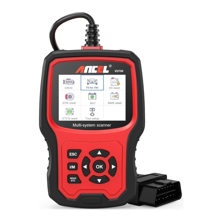
- 2.8'LCD,320 X 240 pixels color screen
- Operating Voltage: 8V-18V
- Operating Temperature: 0ºC-60ºC(32-140ºF)
- Storage Temperature: -20ºC-70ºC(4-158ºF)
Appearance and buttons description

- LCD DISPLAY — Indicates test results. Backlit, 320 x 240 pixels display.
- [OK] BUTTON — Confirms a selection (or action) from a menu.
- ESC BUTTON — Cancels a selection (or action) from a menu or returns to the menu.
- [LEFT] SCROLL BUTTON — in the menu mode through the menu and sub menu move to the left, when rolling in a data interface, use the left button can be moved to the last screen.
- [RIGHT] SCROLL BUTTON — In the menu mode through the menu and sub menu item move to the right, when rolling in the data interface, use the right button can be moved to the next screen.
- [UP] SCROLL BUTTON — in the menu mode through the menu and sub menu item moving up. When retrieving data for more than a screen by moving up the screen to the previous screen for more data.
- [DOWN] SCROLL BUTTON — In the menu mode through the menu and sub menu item moves down. When retrieving data more than one screen, by moving down the screen to the next screen for more data.
- OBD-16PIN CONNECTOR — Connects the scan tool to the vehicle's Data Link Connector (DLC).
- [I/M] BUTTON — Quick State Emissions readiness check and drive cycle verification.

I/M Readiness
Remarks:
MIL Yellow - Dashboard MIL ON
MIL Gray Dashboard MIL OFF
 - not support
 - complete X
 - not complete
- [READ DTC] BUTTON — Quick read the vehicle's fault codes.
OPERATION INSTRUCTIONS
Connect VD700
- Turn the ignition on.
- Locate the vehicle's 16-pin Data Link Connector (DLC).
VD700 Features
- For VW
Choose [For VW ] and then select [Vehicle Scan]. As follows:

![warning]() Remark: [ System Scan] is used to check faulty systems and display the number of faults [ Manual Select ] uses to scan all supported systems.
Remark: [ System Scan] is used to check faulty systems and display the number of faults [ Manual Select ] uses to scan all supported systems.

- Choose [System Scan l, select [ 0017-Dash Board], The screen displays as follows:
- Choose [ 01 -version information ] The screen displays as follows:

- Choose[ Read Fault Codes l. The screen displays as follows:

- Choose[ Erase fault codes l, then press [OK] button.
The screen displays as follows
- Choose[ Read Datastream], if enter number: 005. The screen shows as follows

- Choose [Basic setting], if enter number: 005. The screen shows as follows

- Choose [ Adaptation l, select [ Input channel l, if enter number: 005. The screen displays as follows:

Choose [ Select Function ], select [ Input channel ], if enter number: 005. The screen displays as follows:

- Access Authorization
- Choose [ 01 -version information ] The screen displays as follows:
- Gate way

More further operations, please refer information above. - Battery Regulation

More further operations, please refer information above.


System Selection
- Choose [System Selection], click [Common System],

Select one system to test, more operations, please refer information above.

- Choose [ All System l, the screen displays all supported systems, then select one systems to test.


Crafter (LT3) test
 test")
Special Functions
Choose [Special Functions]:

Choose one of special functions, such as [Service Reset]. Press [ OK ] to continue:

Choose [Flexible Interval], It displays as follows:


 Remark: Before setting the maintenance interval, do set the corresponding [ oil quality ] If vehicle uses UDS protocol, you could do inspection due reset, service reset, and mileage and time settings. Settings of mileage and time support be input manually with any value you want.
EPB reset
Choose [ EPB reset ], press [ OK ] button to continue

- Choose [ EPB replace brake pads ], press [ OK ] button to continue:

Retract the brake pump, please pay attention to the operation tips, and press [OK] button to continue:

- Check whether the brake pump is completely released. The operation of replacing the brake pads is finished, press [ OK ] to complete

- Choose [Retraction Brackpump], press [ OK ] to continue:

- After retract brakepump, press [ OK ] to continue:

- Check whether the retraction is completely, then start to replace the brake pads. After finished, press OK to continue:

- After retract brakepump, press [ OK ] to continue:
- Choose [Release Brake Pump], press [ OK ] to continue:

- Release Brake Pump, and press [ OK ] to continue:

- Release Brake Pump, and press [ OK ] to continue:
- Check whether the brake pump is completely released. The operation of replacing the brake pads is finished, press [ OK ] to complete


Battery Registration
Choose [BMS reset] option, press [OK] button. The screen displays as follow:

Press [ OK ] button again
The screen will displays old battery parameters. It is better to record the parameters to prevent the old battery parameters from being restored when the new battery parameters are not available.

Choose new battery capacity and manufacturer

Remark: If manufacturer is not been indicated in the list, please choose others.
Press [ OK ] button to continue


OBDII diagnosis
Read Codes
Stored codes are also known as "hard codes" or "permanent codes". These codes cause the control module to illuminate the malfunction indicator lamp (MIL) when an emission-related fault occurs.
Pending Codes are also referred to as "maturing codes" or "continuous monitor codes". It indicates the problem that control module has detected during the current or last driving cycle, but they are not considered seriously.
Pending Codes will not turn on the malfunction indicator light, and codes will be cleared from memory if there is no failure during the following warm-up period
- Use the UP/DOWN scroll button to select Read Codes from the Diagnostic Menu and press [OK].

If there are no Diagnostic Trouble Codes, the display indicates "No (pending) codes are stored in the module!" Wait a few seconds or press any key to return to the Diagnostic Menu. - View DTCs and their definitions on screen.


The control module number, sequence of the DTCs, total number of codes detected and type of codes (Generic of Manufacturer specific) will be observed on the upper right hand corner of the display.
Erase Codes
Notes: This function is performed with key on engine off. Do not start the engine. Before performing this function, make sure to retrieve and record the trouble codes. After clearing, you should retrieve trouble codes once more or turn ignition on and retrieve codes again. If there is still some trouble codes for hard troubles, please find the reason caused the trouble code firstly, and then solve the problem. Now, the trouble codes can be erased.
- Use the UP/DOWN scroll buttons to select Erase Codes from the Diagnostic Menu and press [OK].


- A warning message comes up asking for your confirmation.

- Press [OK] to confirm.


I/M Readiness
I/M refers to Inspection and Maintenance, that is legislated by the Government to meet federal clean-air standards. I/M Readiness indicates whether or not the various emissions-related systems on the vehicle are operating properly and are ready for Inspection and Maintenance testing.
The I/M readiness Monitor Status function also can be used (after repair of a fault has been performed) to confirm that the repair has been performed correctly, and/ or to check for Monitor Run Status.

Data Stream
The OBDII Scan Tool is a special diagnostic tool that communicates with the vehicle's computer. The Scan Tool lets you view "real-time" Live Data. This information includes value(volts, rpm, temperature, speed etc.) and system status information (open loop, closed loop, fuel system status, etc.) generated by the various vehicle sensors, switches and actuators.
Press ENTER

Evap Leak Test
This function enables the conditions required to conduct an evaporative system leak test, but does not actually run the test. The vehicle manufacturer is responsible to determine the criteria to automatically stop the test.
Before performing this function, please check the vehicle's service repair manual to determine the necessary procedures.

Vehicle Information. Select [Vehicle Information] and press [ENTER],the screen will display the information such as VIN (Vehicle identification Number), CID (Calibration 'D) and CVN (Calibration verify number).

Tool Setup
Language
Choose [Language] and it displays as follows:

Beeper
Choose [Beeper] and it displays as follows:

Instructions
Choose [Instructions] and it displays as follows:

Unit of measure
Choose Unit of measure and it displays as follows:

Skin style
Choose Unit of measure and it displays as follows:

Feedback
- When the [OBDII] function shows connected error with vehicle, please using the feedback function. Choose [Feedback] and it displays as follows:

Next : Press EXIT Button and return to the main menu. Choose [OBDII] menu to detecting again and it will record the data.

- Transfer data to your computer and generate feedback file.
Download upgrade file on the computer from ANCEL website. The device is connected with computer through USB cable.


Choose "Update" file and it displays as follow:

Click "Feedback" and it displays as follow:

Please send the feedback.bin file to support@anceltech.com.
Device information
Choose Device information and it displays as follows:

Update
- Download update software
- Connect the device with computer through USB cable.


- The update software is only supported by 718/10.
* Windows 8/10 can run update software directly,
* Click "install driver.bat" in the driver files to install the driver, if computer system is Windows 7


Safety precautions
To avoid body injury and damage to the device or your car, please read this manual carefully before using VD700.
The testing process described in the manual is generally the experience of technician. Safety precaution is required in most of the process to avoid body injury and damage to the device or your car.
Read the vehicle maintenance manual before use this device and follow safety precautions.
- It generates CO and other poisonous air when engine is running. To avoid this kind of hurt, please repair the car in a well-air-ventilated place.
- When the engine is running, many parts (such as the coolant fan, pulleys, fan belt etc.) rotate at high speed. To avoid serious injury, always be aware of moving parts. Keep a safe distance from these parts as well as other potentially moving objects.
- Engine parts become very hot when the engine is running. Don't touch hot engine parts to avoid severe burns.
- When the ignition is ON, Connecting or disconnecting test equipment will damage test equipment and the vehicle's electronic components. Turn the ignition OFF before connecting or disconnecting the device from the vehicle's Data Link Connector (DLC).
- Fuel and battery vapors are highly flammable. To prevent an explosion, keep all sparks, heated items and open flames away from the battery and fuel/ fuel vapors. Do not smoke near the vehicle during testing.
Phone:0755-81751202
E-mail: support@anceltech.com
Website: www.anceltech.com
Documents / Resources
References
Download manual
Here you can download full pdf version of manual, it may contain additional safety instructions, warranty information, FCC rules, etc.
Advertisement


Need help?
Do you have a question about the VD700 and is the answer not in the manual?
Questions and answers