Advertisement
Table of Contents
- 1 Important Safety Instructions
- 2 Explanation of Symbols
- 3 Table of Contents
- 4 Introduction
- 5 System Requirements
- 6 Unpacking
- 7 System Concepts
- 8 Illustrations
- 9 Hardware Description
- 10 Software Description
- 11 Installation
- 12 Troubleshooting
- 13 Troubleshooting
- 14 Specifications
- 15 Warranty Information
- Download this manual
Advertisement
Table of Contents
Troubleshooting

Subscribe to Our Youtube Channel
Related Manuals for QSC DCM-1


Summary of Contents for QSC DCM-1
- Page 1 Digital Cinema Monitor & Crossover System *TD-000106-00* TD-000106-00 Rev.B DCM Series USER MANUAL DCM-1 DCM-2 DCM-3...
-
Page 2: Important Safety Instructions
IMPORTANT SAFETY INSTRUCTIONS & EXPLANATION OF SYMBOLS 1- Read these instructions. 2- Keep these instructions. 3- Heed all warnings. 4- Follow all instructions. 5- Do not use this apparatus near water. 6- Clean only with a dry cloth. 7- Do not block any ventilation openings. Install in accordance with QSC Audio Product’s instructions. 8- Do not install near any heat sources such as radiators, heat registers, stoves, or other apparatus (including amplifiers) that produce heat. -
Page 3: Table Of Contents
CONTENTS Introduction...4 System Requirements...5 Unpacking...5 System Concepts...6 Illustrations...8 Hardware Description...11 Software Description...18 Installation...19 Troubleshooting...29 Specifications...32 Warranty Information...34 The DCM hardware unit and DCM Manager software are the property of QSC Audio Inc. Information in this document is subject to change without notice and does not represent a commitment on the part of QSC Audio. -
Page 4: Introduction
INTRODUCTION INTRODUCTION Thank you and congratulations on your purchase of the QSC DCM Digital Cinema Monitor. This product represents the state-of-the-art for cinema-based signal processing and monitoring functions in a single, integrated system. Designed to compliment QSC’s DCA (Digital Cinema Amplifier) Series amplifier products, the DCM optimizes loudspeaker performance while facilitating easy cinema sound system wiring and configuration. -
Page 5: System Requirements
SYSTEM REQUIREMENTS and UNPACKING SYSTEM REQUIREMENTS DCM Manager software is designed to control one DCM hardware unit at a time. To use this software with the DCM hardware unit, you must have the following: 1- Digital Cinema Monitor unit 2- DCM Manager software installation CD 3- IBM-compatible PC with a 200 MHz Pentium processor (or better) Windows 98, NT, XP, or 2000 Microsoft®... -
Page 6: System Concepts
SYSTEM CONCEPTS SYSTEM CONCEPTS System Design Features The DCM series Digital Cinema Monitor has many unique features which combine to make this the most cost effective and versatile systems solution in the industry. Installer Features: •Provides Monitor and Crossover functions in one box. •Minimizes the amount of cabling required. - Page 7 SYSTEM CONCEPTS 3. DSP processing: Digital filtering of audio signals is known to have several advantages over analog solutions. DSP (digital signal processor) IC chips allow extremely accurate and reliable control of frequency and time adjustments (boost, cut, cutoff frequency, delay time), and stability (immunity from temperature variations).
-
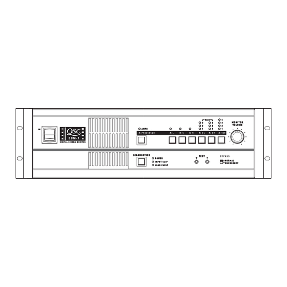
Page 8: Illustrations
ILLUSTRATIONS- DCM-1 DCM-1 FRONT PANEL 1- Power switch 2- Monitor output speaker 3- Processor/Amps selector switch 4- Monitor source selector switches 5- Monitor volume control DCM-1 REAR PANEL 1- Emergency bypass level controls 2- Subwoofer output 3- Hearing Impaired system output... - Page 9 ILLUSTRATIONS- DCM-2 DCM-2 FRONT PANEL 1- Power switch 2- Monitor output speaker 3- Processor/Amps selector switch 4- Monitor source selector switches 5- Monitor volume control DCM-2 REAR PANEL 1- Emergency bypass level controls & bypass switches 2- DataPort outputs to amplifiers 3- Audio input connector (from Cinema Processor) 4- Subwoofer output 5- Hearing Impaired system output...
- Page 10 ILLUSTRATIONS- DCM-3 DCM-3 FRONT PANEL 1- Power switch 2- Monitor output speaker 3- Amplifier/Processor selector switch 4- Monitor source selector switches 5- Monitor volume control DCM-3 REAR PANEL 1- Emergency bypass level controls & bypass switches 2- DataPort outputs to amplifiers 3- Audio input connector (from Cinema Processor) 4- Subwoofer output 5- Hearing Impaired system output...
-
Page 11: Hardware Description
When the switch is in the off position, all the amplifiers will be in Standby mode. Same as above EXCEPT that Center Channel (DataPort B & C) will remain on even if the DCM Power switch is set to the off position. For the DCM-1 only DataPort B remains on. - Page 12 HARDWARE DESCRIPTION- FRONT PANEL (continued) Monitor Source Selection Switches: Pressing any of the Monitor Select buttons will either select or deselect the corresponding (marked) signal for monitoring. Each button can select either the Proces- sor signals (input to the DCM) or the Amplifier signals (output to the speakers), depending on the current selection of the PROC/AMP switch.
- Page 13 HARDWARE DESCRIPTION- FRONT PANEL (continued) Diagnostics Check Button and Indicators: The Diagnostics / Indicator section includes an ex- tremely simple method of verifying proper system operation and performing basic troubleshooting. The Power LED shows whether the DCM unit is on or off. The Input Clip LED is helpful in verifying that the cinema format processor is not over-driving the DCM input circuitry.
- Page 14 HARDWARE DESCRIPTION- FRONT PANEL (continued) Test Jacks: The Test jacks give you access to any of the signals being sent to the front panel speaker (before the gain potentiometer). These signal levels are at the exact same level as the cinema processor output signals (unity gain) and can be used as a test point for system calibration.
-
Page 15: Rear Panel
Technical Services Group. The maximum output configuration on the DCM-1 is a 6 ch / 2-way, the maximum on the DCM-2 is a 6 ch / 3-way, and the maximum output configuration on the DCM-3 is a 8 ch / 3 way. In addition, many parallel outputs (with separate processing) are included for additional theater configuration flexibility. - Page 16 HARDWARE DESCRIPTION- REAR PANEL (continued) From Processor Output: This connection is from the cinema processor, and is the input source of all film sound into the DCM unit. The 25-pin connector is an industry standard type and pinout, and will connect into your system very easily.
- Page 17 AC voltage. 85 to 260 VAC (50/60 Hz.) is the acceptable AC voltage. The IEC connector also houses the fuses for the DCM. If fuse replacement is required, use only Littlefuse #218 001 or Bussman #S5504-1A. Rear Panel DCM-1 Terminal Strip Connections DCM-2 and -3 Terminal Strip Connections...
-
Page 18: Software Description
SOFTWARE DESCRIPTION DCM MANAGER WINDOWS SOFTWARE To access the powerful crossover and system calibration functions of the DCM hardware, you must use the DCM Manager control software. A 9-pin male to female serial data cable is also needed to connect your PC to the DCM. One of the computer’s available COM ports (RS-232) provides communications between the DCM Manager software and the DCM hardware. -
Page 19: Installation
INSTALLATION- Rack Mounting RACK MOUNTING Rack mounting of the DCM is optional. Four, self-adhesive rubber feet are included with your DCM for non- rack mount applications. If using the DCM in non-rackmount applications, we recommend the rubber feet be installed on the bottom of your DCM to minimize the chances of scratching any supporting surface. To use the self-adhesive feet: peel off the protective backing from the foot, place near one of the corners on the bottom, and press firmly to activate the pressure-sensitive adhesive. - Page 20 INSTALLATION- Rear Rack Ears (optional accessory) SUPPORTING THE REAR OF THE DCM (requires optional hardware) For mobile and touring use, it is extremely important to support the rear of the DCM. The chassis and rack can be damaged if the DCM is not properly supported. Unless the DCM is being installed in its final, fixed location, QSC strongly recommends supporting the rear of the unit.
-
Page 21: Ac Mains Connection
INSTALLATION- Connections: General Information and AC Mains CONNECTIONS Making the required connections to the DCM is simple. Just make sure that you have all of the correct cables. “Mass-termination” connectors are used wherever possible. This reduces installation time from hours to minutes and makes any required connection changes fast, easy, and reliable. REQUIRED CABLES (typical system) 1- IEC-style AC power cord (included with the DCM) 2- QSC DataPort cable for every amplifier (8, 11, or 15 cables depending upon model) - Page 22 INSTALLATION- Connections: RS-232 RS-232 CONNECTION The RS-232 port is used only for setup and system troubleshooting. Connect the 9-pin serial data cable from the host PC to this connector on the DCM. Orient the male DB9 connector to match up with the RS-232 port, push the connector into the receptacle to seat it, and finger-tighten the retaining screws.
-
Page 23: Dataport Connection
V- MON Ch. 2 and Subcode 3 I- MON Ch. 2 and Subcode 4 Clip/Protect Ch. 2 DCM-1 DataPorts shown, other models similar. Use QSC DataPort cables. Contact QSC’s Techni- cal Services Group if you would like to purchase standard length DataPort cables or specially made custom length cables that use shielded audio-pairs for the best possible performance. - Page 24 INSTALLATION- Connections: Cinema Processor CINEMA PROCESSOR CONNECTION Audio signals are input to the DCM via the FROM PROCESSOR OUTPUT connection. This DB25-type connection conforms to cinema industry standard pinout. Most common cinema processors use this DB25 connec- tion standard, making connection to the DCM simple. Orient the DB25-type connector properly, push gently to seat the pins, then finger-tighten the retaining screws.
- Page 25 Use balanced audio connections and high-quality, shielded, balanced audio cable for interconnecting the DCM and Powered Subwoofer equipment. Balanced connections are less prone to noise pick-up than unbalanced connections. DCM-1 Terminals Connect other end of cable according to equipment manufacturer’s instructions.
- Page 26 Signal Description Surround Left Send Surround Right Send Signal Ground Surround Left Return Surround Right Return Signal Ground Signal Ground Surround Back Left Return Surround Back Right Return DCM-1 Surround Insert Connector and Selector Switch DCM-2 and -3 Surround Insert Connector...
-
Page 27: System Calibration
Normal position to the sound while in the Emergency position. While in the bypassed position, adjust the potentiometers to most closely match the normal position sound. DCM-1 Bypass Level Controls DCM-2 and -3 Bypass Level Controls... - Page 28 INSTALLATION- System Calibration 3. Monitoring - audio mix adjustments The DCM Manager software allows balancing of the high/low or high/mid/low signals being fed to the front panel monitor speaker. Input pink noise into all of the DCM input channels and select individual channels using the DCM front panel buttons.
-
Page 29: Troubleshooting
TROUBLESHOOTING If the DCM Manager program is unable to communicate with the DCM hardware... • Verify the RS-232 cable connections. Re-seat each cable-end and finger-tighten connector retaining screws. • Make sure the 9-pin serial data cable (RS-232 cable) is a normal type cable. “Null-modem” or other “special”... - Page 30 TROUBLESHOOTING If some of the front panel LEDs don’t illuminate... • The DCM will only select and monitor amplifier channels that have been enabled using the DCM Man- ager program. The front panel LEDs and audio monitoring only allow use of channels set in the software. Connect the host PC to the DCM and run the DCM Manager program.
-
Page 31: Troubleshooting
TROUBLESHOOTING If theater audio is distorted ... • Verify that the DCM Input Clip LED is not lit. If it is, the cinema processor output signal needs to be turned down. •If any of the amplifier CLIP warning LEDs are illuminating, the output level of the DCM must be reduced or amplifier input sensitivity must be reduced. -
Page 32: Specifications
Loading Requirements Active balanced 20k ohms +14.2 dBu (4.0 Vrms) 24-bit delta-sigma 128x oversampled (analog subwoofer on DCM-1) Hardwire pass-thru to DataPort Outputs (via Surround-EX insert) +6 to -18 dB in 0.1 dB steps 99 dB 0.02%, 20 hertz to 20 kilohertz, all filters flat... - Page 33 FCC Class A IEC style detachable cord receptacle 9-pin D-sub female receptacle 25-pin D-sub female receptacle DCM-1 Eight 15-pin D-sub HD female receptacles DCM-2 Eleven 15-pin D-sub HD female receptacles DCM-3 Fifteen 15-pin D-sub HD female receptacles 9 pin D-sub male receptacle...
-
Page 34: How To Contact Qsc Audio Products
WARRANTY INFORMATION & HOW TO CONTACT QSC WARRANTY (USA only; other countries, see your dealer or distributor) Disclaimer QSC Audio Products, Inc. is not liable for any damage to speakers, amplifiers, or any other equipment that is caused by negligence or improper installation and/or use of this cinema product. Product Warranty QSC Audio Products, Inc. - Page 35 This page intentionally left blank.
- Page 36 QSC Audio Products, Inc. 1675 MacArthur Boulevard Costa Mesa, California 92626 USA “QSC” and the QSC logo are registered with the U.S. Patent and Trademark Office. ©2002 QSC Audio Products, Inc.
Need help?
Do you have a question about the DCM-1 and is the answer not in the manual?
Questions and answers