Table of Contents
Advertisement
Advertisement
Table of Contents

Related Manuals for MSI 915G Combo


Summary of Contents for MSI 915G Combo
- Page 1 915P/G Combo MS-7058 (v1.X) ATX Mainboard G52-M7058X6...
-
Page 2: Fcc-B Radio Frequency Interference Statement
Manual Rev: 1.0 Release Date: May 2004 FCC-B Radio Frequency Interference Statement This equipment has been tested and found to comply with the limits for a class B digital device, pursuant to part 15 of the FCC rules. These limits are designed to provide reasonable protection against harmful interference when the equipment is operated in a commercial environment. -
Page 3: Copyright Notice
Copyright Notice The material in this document is the intellectual property of MICRO-STAR INTERNATIONAL. We take every care in the preparation of this document, but no guarantee is given as to the correctness of its contents. Our products are under continual improvement and we reserve the right to make changes without notice. -
Page 4: Safety Instructions
Alternatively, please try the following help resources for further guidance. Visit the MSI homepage & FAQ site for technical guide, BIOS updates, driver updates, and other information: http://www.msi.com.tw & http://www.msi. -
Page 5: Table Of Contents
CONTENTS FCC-B Radio Frequency Interference Statement ............iii Copyright Notice ......................iii Revision History ......................iii Safety Instructions ...................... iv Technical Support ......................iv Chapter 1. Getting Started ................... 1-1 Mainboard Specifications ................... 1-3 Mainboard Layout ....................1-4 Packing Contents ....................1-5 Chapter 2. - Page 6 CD-In Connector: JCD1 ................2-17 Front Panel Connectors: JFP1, JFP2 ............2-17 IEEE 1394 Connectors: J1394_1, J1394_2, J1394_3 (Optional) ... 2-18 Front Panel Audio Connector: JAUD2 ............. 2-18 IrDA Infrared Module Header: JIR1 ............2-19 Front USB Connectors: JUSB1 & JUSB2 ..........2-19 Chassis Intrusion Switch Connector: JCI1 ..........
- Page 7 Terminology ....................4-6 Access Point Mode ..................4-7 WLAN Card Mode ..................4-8 Live Update ......................4-9 MEGA STICK ...................... 4-10 Basic Function ..................4-10 Non-Unicode programs supported ............4-12 Core Center (for Pentium 4 CPU) ..............4-14 Left-wing: Current system status ............4-15 Right-wing: PC hardware status during real time operation ....
- Page 8 Rebuild Broken RAID 0/0+1 Array ............6-12 Installing Software .................... 6-14 Install Driver in Windows 2000/XP ............6-14 Installation of VIA IDE RAID Utility ............6-15 Using VIA RAID Tool ..................6-18 Chapter 7. Introduction to CMI9880L Audio Codec ........7-1 Installing the Audio Codec Driver ...............
-
Page 9: Chapter 1. Getting Started
Getting Started Chapter 1. Getting Started Getting Started Thank you for choosing the 915P/G Combo (MS-7058) v1.X ® ATX mainboard. The 915P/G Combo mainboard is based on Intel ® 915P/G and Intel ICH6/ICH6R chipset for optimal system efficiency. Designed to fit the advanced Intel ®... -
Page 10: Mainboard Specifications
Supports Intel Pentium 4 Prescott LGA775 processors in LGA775 package. Supports up to Pentium 4 3XX, 5XX & 7XX sequence processor or higher speed. Supports Intel Hyper-Threading Technology. (For the latest information about CPU, please visit http://www.msi.com.tw/program/ products/mainboard/mbd/pro_mbd_cpu_support.php) Chipset ®... - Page 11 Getting Started VIA6410 IDE Raid Controller (Optional) Two Ultra DMA 66/100/133 IDE Controllers. Supports RAID 0, 1 and 0+1. Connect up to 4 Ultra ATA 133 devices. On-Board Peripherals On-Board Peripherals include: - 1 floppy port supports 1 FDD with 360K, 720K, 1.2M, 1.44M and 2.88Mbytes - 1 serial port - 1 VGA port (for 915G only, Optional) - 1 parallel port supports SPP/EPP/ECP mode...
-
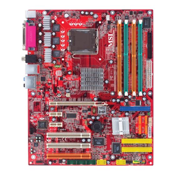
Page 12: Mainboard Layout
7058 ATX Mainboard Mainboard Layout JC11 CPUFAN1 Top : mouse JIR11 Bottom : k eyboard Top : Pa ra llel Port Bottom : COM A VGA port (Optiona l) SPDIFO ut B:USB port JPW1 T: LAN jac k B: USB ports Intel 915P/G Line-In... -
Page 13: Packing Contents
Getting Started Packing Contents MSI Driver/Utility CD SATA Cable *2 MSI motherboard D-Bracket 2 Standard Cable for Power Cable (Optional) IDE Devices Standard Cable for User’s Guide Back IO Shield Floppy Disk... -
Page 14: Chapter 2. Hardware Setup
Hardware Setup Chapter 2. Hardware Setup Hardware Setup This chapter tells you how to install the CPU, memory modules, and expansion cards, as well as how to setup the jumpers on the mainboard. Also, it provides the instructions on connecting the periph- eral devices, such as the mouse, keyboard, etc. -
Page 15: Quick Components Guide
MS-7058 ATX Mainboard Quick Components Guide JPW1, p.2-9 CPUFAN1, p.2-9 DDR DIMMs, p.2-7 NBFAN1, p.2-9 JCI1, p.2-20 JIR1, p.2-19 FDD1, p.2-14 Back Panel I/O, p.2-10 ATX1, p.2-9 PCI Express x16, IDE1, p.2-15 p.2-22 JBAT1, p.2-22 PCI Express x1, PWRFAN1, p.2-14 p.2-22 SYSFAN1, p.2-14 JCD1, p.2-18... -
Page 16: Central Processing Unit: Cpu
If you do not have the CPU cooler, contact your dealer to purchase and install them before turning on the computer. For the latest information about CPU, please visit http://www.msi.com.tw/ program/products/mainboard/mbd/pro_mbd_cpu_support.php. MSI Reminds You... -
Page 17: Cpu & Cooler Installation
4 fingers to push the CPU Clip down to clip them (the CPU clip is up and the CPU is down) together. MSI Reminds You... 1. Confirm if your CPU cooler is firmly installed before turning on your system. 2. Do not touch the CPU socket pins to avoid damaging. - Page 18 Hardware Setup 5. The CPU has a plastic cap on it to 6. Remove the cap from lever hinge side protect the contact from damage. (as the arrow shows). Before you have installed the CPU, always cover it to protect the socket pin.
- Page 19 MSI Reminds You... 1. Check the information in PC Health Status of H/W Monitor in BIOS (refer to p.3-20 for details) for the CPU temperature. 2. Whenever CPU is not installed, always protect your CPU socket pin with the plastic cap covered (shown in Figure 1) to avoid damaging.
-
Page 20: Memory
DDR2 slot (DIMM1 & DIMM3), and DDR1 memory module in DDR1 slot (DIMM2 & DIMM4). Wrong installation may cause damage of mainboard. Meanwhile, you are not able to boot up your system if you install DDR1 & DDR2 memory modules simultaneously. For the updated supporting memory modules, please visit http://www.msi. com.tw/program/products/mainboard/mbd/pro_mbd_trp_list.php. DIMM1~DIMM4 (from left to right) DIMM1 &... -
Page 21: Memory Module Population Rules
The plastic clip at each side of the DIMM slot will automatically close. Notch Volt MSI Reminds You... You can barely see the golden finger if the module is properly in- serted in the socket. -
Page 22: Power Supply
JPW1 Pin Definition SIGNAL JPW1 MSI Reminds You... 1. These two connectors connect to the ATX power supply and have to work together to ensure stable operation of the mainboard. 2. Power supply of 350 watts (and above) is highly recommended for system stability. -
Page 23: Back Panel
MS-7058 ATX Mainboard Back Panel The back panel provides the following connectors: RS-Out L-In Parallel Mouse S/PDIF VGA port USB Ports CS-Out COM A L-Out Keyboard (Optional) SPDIF Out Mouse/Keyboard Connector ® The mainboard provides a standard PS/2 mouse/keyboard mini DIN connector ®... -
Page 24: Serial Port Connector
Hardware Setup Serial Port Connector The mainboard offers one 9-pin male DIN connector as the serial port. The port is a 16550A high speed communication port that sends/receives 16 bytes FIFOs. You can attach a serial mouse or other serial devices directly to the connector. Pin Definition 1 2 3 4 5 SIGNAL... -
Page 25: Lan (Rj-45) Jack
MS-7058 ATX Mainboard LAN (RJ-45) Jack The mainboard provides 1 standard RJ-45 jack for connection to single Local Area Network (LAN). This Giga-bit LAN enables data to be transferred at 1000, 100 or 10Mbps. You can connect a network cable to it. Giga-bit LAN Pin Definition SIGNAL DESCRIPTION... -
Page 26: Parallel Port Connector: Lpt1
Hardware Setup Parallel Port Connector: LPT1 The mainboard provides a 25-pin female centronic connector as LPT. A parallel port is a standard printer port that supports Enhanced Parallel Port (EPP) and Ex- tended Capabilities Parallel Port (ECP) mode. Pin Definition SIGNAL DESCRIPTION STROBE... -
Page 27: Connectors
SYSFAN1 PWRFAN1 NBFAN1 CPUFAN2 MSI Reminds You... 1. Always consult the vendors for proper CPU cooling fan. 2. CPUFAN2 supports the fan control. Fan/heatsink with 3 or 4 fins are both available. 3. Be sure to configure the CPU FAN PIN Select in BIOS for the CPU Fan you are using first. -
Page 28: Hard Disk Connectors: Ide1, Ide2 & Ide3 (Ide 2 & Ide3 Are Optional)
IDE2, IDE3 (Third and Secondary IDE Connector) IDE2 & IDE3 can also connect a Slave and a Master drive. MSI Reminds You... If you install two hard disks on cable, you must configure the second drive to Slave mode by setting its jumper. Refer to the hard disk documentation supplied by hard disk vendors for jumper setting instructions. -
Page 29: Serial Ata/Serial Ata Raid Connectors Controlled By
Take out the dust cover and connect to the hard disk devices Connect to serial ATA ports MSI Reminds You... Please do not fold the serial ATA cable in a 90-degree angle, since this might cause the loss of data during the transmission. 2-16... -
Page 30: Cd-In Connector: Jcd1
Hardware Setup CD-In Connector: JCD1 The connector is for CD-ROM audio connector. JCD1 Front Panel Connectors: JFP1 & JFP2 The mainboard provides two front panel connectors for electrical connection ® to the front panel switches and LEDs. JFP1 is compliant with Intel Front Panel I/O Connectivity Design Guide. -
Page 31: Ieee 1394 Connectors: J1394_1, J1394_2, J1394_3 (Optional)
MS-7058 ATX Mainboard IEEE 1394 Connectors: J1394_1, J1394_2, J1394_3 (Optional) The mainboard provides three 1394 pin headers that allow you to connect IEEE 1394 ports via an external IEEE1394 bracket. Pin Definition SIGNAL SIGNAL TPA+ TPA- Ground Ground TPB+ TPB- J1394_1~J1394_3 Cable power Cable power... -
Page 32: Irda Infrared Module Header: Jir1
Hardware Setup IrDA Infrared Module Header: JIR1 The connector allows you to connect to IrDA Infrared module. You must con- figure the setting through the BIOS setup to use the IR function. JIR1 is compliant with Intel ® Front Panel I/O Connectivity Design Guide. JIR1 Pin Definition Signal Signal... -
Page 33: Chassis Intrusion Switch Connector: Jci1
MS-7058 ATX Mainboard Chassis Intrusion Switch Connector: JCI1 This connector is connected to a 2-pin chassis switch. If the chassis is opened, the switch will be short. The system will record this status and show a warning message on the screen. To clear the warning, you must enter the BIOS utility and clear the record. -
Page 34: Jumpers
JBAT1 Keep Data Clear Data MSI Reminds You... You can clear CMOS by shorting 2-3 pin while the system is off. Then return to 1-2 pin position. Avoid clearing the CMOS while the system is on; it will damage the mainboard. -
Page 35: Slots
BIOS configuration. The orange PCI slot (PCI3) supports 2 masters, therefore it can also work as a communication slot. You may install the communication card on this slot, such as the wireless LAN PCI cards of MSI. PCI Slots 2-22... -
Page 36: Pci Interrupt Request Routing
Hardware Setup PCI Interrupt Request Routing The IRQ, acronym of interrupt request line and pronounced I-R-Q, are hard- ware lines over which devices can send interrupt signals to the microprocessor. The PCI IRQ pins are typically connected to the PCI bus INT A# ~ INT D# pins as follows: Order 1 Order 2 Order 3... -
Page 37: Chapter 3. Bios Setup
An error message appears on the screen during the system boot up, and requests you to run SETUP. You want to change the default settings for customized features. MSI Reminds You... 1. The items under each BIOS category described in this chapter are under continuous update for better system performance. -
Page 38: Entering Setup
MS-7058 ATX Mainboard Entering Setup Power on the computer and the system will start POST (Power On Self Test) process. When the message below appears on the screen, press <DEL> key to enter Setup. DEL: Setup Menu TAB: Logo F11: Boot Menu F10: Flash Recovery If the message disappears before you respond and you still wish to enter Setup, restart the system by turning it OFF and On or pressing the RESET button. -
Page 39: Control Keys
The preset Optimal Defaults of the BIOS setup program provide optimal performance settings for all devices and the system. MSI Reminds You... The items under each BIOS category described in this chapter are under continuous update for better system performance. Therefore, the description may be slightly different from the latest BIOS and should be held for reference only. -
Page 40: The Main Menu
MS-7058 ATX Mainboard The Main Menu Once you enter AMIBIOS NEW SETUP UTILITY, the Main Menu will appear on the screen. Use arrow keys to move among the items and press <Enter> to enter the sub-menu. Standard CMOS Features Use this menu for basic system configurations, such as time, date etc. Advanced BIOS Features Use this menu to setup the items of AMI ®... - Page 41 BIOS Setup Load Fail-Safe Defaults Use this menu to load the default values set by the BIOS vendor for stable system performance. Load Optimized Defaults Use this menu to load the default values set by the mainboard manufacturer specifi- cally for optimal performance of the mainboard. BIOS Setting Password Use this menu to set the password for BIOS.
-
Page 42: Standard Cmos Features
MS-7058 ATX Mainboard Standard CMOS Features The items in Standard CMOS Features Menu includes some basic setup items. Use the arrow keys to highlight the item and then use the <+> or <-> keys to select the value you want in each item. Date (MM:DD:YY) This allows you to set the system to the date that you want (usually the current date). - Page 43 BIOS Setup Device This item shows the information about the specified item. Read-only. LBA/Large Mode This item allows you to enable or disable the LBA (Logical Block Address, the logical block size in hard disk) mode. Setting options: [Auto], [Disabled]. DMA Mode This item allows you to enable or disable the DMA (Direct Memory Access) mode.
-
Page 44: Advanced Bios Features
MS-7058 ATX Mainboard Advanced BIOS Features Quick Boot Setting the item to [Enabled] allows the system to boot within 5 seconds since it will skip some check items. Available options: [Enabled], [Disabled]. Boot Sector Protection This function protects the BIOS from accidental corruption by unauthorized users or computer viruses. - Page 45 BIOS Setup MSI Reminds You... Enabling the functionality of Hyper-Threading Technology for your com- puter system requires ALL of the following platform Components: ® ® * CPU: An Intel Pentium 4 Processor with HT Technology; ® * Chipset: An Intel Chipset that supports HT Technology;...
-
Page 46: Advanced Chipset Features
MS-7058 ATX Mainboard Advanced Chipset Features MSI Reminds You... Change these settings only if you are familiar with the chipset. Configure DRAM Timing by SPD Selects whether DRAM timing is controlled by the SPD (Serial Presence Detect) EEPROM on the DRAM module. Setting to [Auto By SPD] enables DRAM timings and the following related items to be determined by BIOS based on the configurations on the SPD. -
Page 47: Integrated Peripherals
BIOS Setup Integrated Peripherals USB Controller This setting is used to enable/disable the onboard USB host controller. Setting options: [Disabled], [Enabled]. USB Device Legacy Support Set to [Enabled] if you need to use any USB 1.1/2.0 device in the operating system that does not support or have any USB 1.1/2.0 driver installed, such as DOS. - Page 48 MS-7058 ATX Mainboard Disable the function if you want to use other controller cards to connect an audio device. Settings: [Disabled] and [Enabled]. IDE Devices Configuration Press <Enter> to enter the sub-menu and the following screen appears: PCI IDE BusMaster Set this option to [Enabled] to specify that the IDE controller on the PCI local bus has bus mastering capability.
- Page 49 BIOS Setup [Full Duplex], [Half Duplex]. Under [Full Duplex] mode, synchronous, bi-directional transmission/reception is allowed. Under [Half Duplex] mode, only asynchronous, bi- directional transmission/reception is allowed. Parallel Port This field specifies the base I/O port address of the onboard parallel port. Selecting [Auto] allows AMIBIOS to automatically determine the correct base I/O port address.
-
Page 50: Power Management Features
MS-7058 ATX Mainboard Power Management Features MSI Reminds You... S3-related functions described in this section are available only when your BIOS supports S3 sleep mode. ACPI Function This item is to activate the ACPI (Advanced Configuration and Power Management Interface) Function. If your operating system is ACPI-aware, such as Windows 98SE/ 2000/ME/XP, select [Enabled]. - Page 51 BIOS Setup Power Button Function This feature allows users to configure the Power Button function. Settings are: [Power Off] The power button functions as a normal power-on/-off button. [Suspend] When you press the power button, the computer enters the suspend/sleep mode, but if the button is pressed for more than four seconds, the computer is turned off.
- Page 52 Time (HH:MM:SS) 00 ~ 23 : 00 ~ 59 : 00 ~ 59 MSI Reminds You... If you have changed this setting, you must let the system boot up until it enters the operating system, before this function will work.
-
Page 53: Pnp/Pci Configurations
BIOS Setup PNP/PCI Configurations This section describes configuring the PCI bus system and PnP (Plug & Play) feature. PCI, or Peripheral Component Interconnect, is a system which allows I/O devices to operate at speeds nearing the speed the CPU itself uses when communicating with its special components. - Page 54 MS-7058 ATX Mainboard over. When set to higher values, every PCI device can conduct transactions for a longer time and thus improve the effective PCI bandwidth. For better PCI performance, you should set the item to higher values. Setting options: [32], [64], [96], [128], [160], [192], [224], [248].
-
Page 55: H/W Monitor
BIOS Setup H/W Monitor This section shows the status of your CPU, fan, overall system status, etc. Monitor function is available only if there is hardware monitoring mechanism onboard. CPU Fan Failure Warning When enabled, the system will automatically monitor the CPU fan during boot-up. If it detects that the CPU fan is not rotating, the system will show an error message on the screen and halt the boot-up process. - Page 56 MS-7058 ATX Mainboard PC Health Status Press <Enter> and the following sub-menu appears. CPU/System Temperature, CPU/NB FAN Speed, Vcore, +3.3 V, +5.0 V, +12.0V, +5VSB These items display the current status of all of the monitored hardware devices/ components such as CPU voltages, temperatures and all fans’ speeds. 3-20...
-
Page 57: Cell Menu
Cell Menu The items in Cell Menu includes some important settings of CPU, AGP, DRAM and overclocking functions. MSI Reminds You... Change these settings only if you are familiar with the chipset. Current CPU Clock, Current DDR Memory Frequency These two items show the current clocks of CPU & DDR memory frequency. Read- only. - Page 58 [Commander] 6th level of overclocking, increasing the CPU frequency by 15%. (For 915P Only) MSI Reminds You... 1. Even though the Dynamic Overclocking Technology is more stable than manual overclocking, basically, it is still risky. We suggest user to make sure that your CPU can afford to overclock regularly first.
- Page 59 10%. [Commander] 6th level of overclocking, increasing the PCI Express frequency by 15%. MSI Reminds You... Even though the Dynamic Overclocking Technology is more stable than manual overclocking, basically, it is still risky. We suggest user to make sure that your PCI Express can afford to overclock regularly first.
- Page 60 NorthBridge voltage is adjustable in the field, allowing you to increase the perfor- mance of your NorthBridge when overclocking, but stability may be affected. MSI Reminds You... The settings shown in different color in CPU Voltage, DDR Voltage and NB Voltage help to verify if your setting is proper for your system.
-
Page 61: Bios Setting Password
BIOS Setup BIOS Setting Password When you select this function, a message as below will appear on the screen: Type the password, up to six characters in length, and press <Enter>. The password typed now will replace any previously set password from CMOS memory. You will be prompted to confirm the password. -
Page 62: Load Fail-Safe/Optimized Defaults
MS-7058 ATX Mainboard Load Fail-Safe/Optimized Defaults The two options on the main menu allow users to restore all of the BIOS settings to the default Fail-Safe or Optimized values. The Optimized Defaults are the default values set by the mainboard manufacturer specifically for optimal performance of the mainboard. -
Page 63: Chapter 4. Introduction To Digicell
Chapter 2. Hardware Setup Introduction to DigiCell DigiCell, the most useful and powerful utility that MSI has spent much research and efforts to develop, helps users to monitor and configure all the integrated peripherals of the system, such as audio program, power management, MP3 files management and communication / 802.11g WLAN... -
Page 64: Main
Introduction: Click on each icon appearing above to enter the sub-menu to make further configuration. Click on this button to link to MSI website: http://www.msi.com.tw. Quick Guide Click on this button and the quick guide of DigiCell will be displayed for you to review. - Page 65 Power on Agent In this sub-menu, you can configure date, time and auto-executed programs of the power-on, power-off and restarting features. MSI Reminds You... Click on back button in every sub-menu and it will bring you back to the main menu.
-
Page 66: H/W Diagnostic
In the H/W Diagnostic sub-menu, you can see the information, status and note of each DigiCell. You may double check the connection and installation of the item marked as gray. You may also click on the Mail to MSI button to send your questions or suggestions to MSI’s technical support staff. -
Page 67: Communication
Introduction to DigiCell Communication In the Communication sub-menu, you can see the status of all the LAN / WLAN / Bluetooth on the screen if the hardware is installed. The first icon indicates the onboard LAN on your system, the second icon indicates the wireless LAN status, and the third one is the information about the bluetooth on your system. -
Page 68: Software Access Point
MS-7058 ATX Mainboard MSI Feature Software Access Point In the Software Access Point sub-menu, you can see the communication status on your system and choose the desired software access point mode by clicking on the desired icon. The default settings are configured for your usage. The default soft- ware access point mode is set to WLAN Card Mode. -
Page 69: Access Point Mode
Introduction to DigiCell Access Point Mode Click on “Setting” button of the Access Point Mode and the following screen will display. IP Sharing Click on this icon to enable/disable the IP sharing. The default of this setting is disabled. Disabled. Enabled. -
Page 70: Wlan Card Mode
MS-7058 ATX Mainboard MSI Feature enable this feature, only PCs with MAC address located in Association Control List can connect to the wireless LAN. MAC Address MAC stands for Media Access Control. A MAC address is the hardware address of a device connected to a network. -
Page 71: Live Update
BIOS/VGA Driver/OSD/Utility online so that you don’t need to search for the correct BIOS/driver version throughout the whole Web site. To use the function, you need to install the “MSI Live Update 3” application. After the installation, the “MSI Live Update 3”... -
Page 72: Mega Stick
MS-7058 ATX Mainboard MSI Feature MEGA STICK In the MEGA STICK sub-menu, you can configure the settings of MSI MEGA STICK and the media files (*.m3u, *.mp3, *.wav, *.cda, *.wma) on your system. Basic Function Here you can edit your own play list with the buttons “load”, “save”, “delete”, “shuttle”, “repeat”... - Page 73 Introduction to DigiCell There is also a toolbar for you to execute some basic function, like play, stop, pause, previous/next song, song info and volume adjust. There is also a scroll bar on the top for you to forward/rewind. pause previous next forward/rewind...
-
Page 74: Non-Unicode Programs Supported
MS-7058 ATX Mainboard MSI Feature Non-Unicode programs supported If you are using an operating system in European languages, and you’d like to play the media files in MEGA STICK with East-Asian languages (such as Chinese, Japanese... etc.), it is possible that the file names will display incorrectly. - Page 75 Introduction to DigiCell 3. Then go to the [Advanced] tab and select the language you want to be supported (the language of the filename in the MegaStick) from the drop- down list in the [Language for non-Unicode programs], then click [Apply]. The system will install the necessary components from your Microsoft Setup CD immediately.
-
Page 76: Core Center (For Pentium 4 Cpu)
MS-7058 ATX Mainboard MSI Feature Core Center (for Pentium 4 CPU) Click on the Core Center icon in the main menu and the Core Center program will be enabled. CoreCenter is just like your PC doctor that can detect, view and adjust the PC hardware and system status during real time operation. -
Page 77: Left-Wing: Current System Status
Introduction to DigiCell Left-wing: Current system status In the left sub-menu, you can configure the settings of FSB, Vcore, Memory Voltage and AGP Voltage by clicking the radio button next to each item and make it available (the radio button will be lighted as yellow when selected), use the “+” and “-” buttons to adjust, then click “OK”... -
Page 78: Audio Speaker Setting
MS-7058 ATX Mainboard MSI Feature Audio Speaker Setting In the Audio Speaker Setting sub-menu, you can configure the multi-channel audio operation, perform speaker test, and choose the environment you prefer while en- joying the music. You can scroll the bar of each equalizer to regulate for current playing digital sound source. - Page 79 Center Front Right Front Left Side Right Side Left Rear Right Rear Left Subwoofer MSI Reminds You... For the advanced functions of the audio codec, please refer to Chapter 7: Introduction to CMI 9880L Audio Codec for details. 4-17...
-
Page 80: Power On Agent
Click “OK” to restart the computer right away or click “Later” to restart your computer later. MSI Reminds You... Please note that the new setting will not take effect until you restart your computer. -
Page 81: Power Off / Restart
Delete. delete the added program MSI Reminds You... You can also enable the Every turn on function, which will enable the specified program(s) and file(s) every time the Digi Cell utility runs. -
Page 82: Auto Login
MS-7058 ATX Mainboard MSI Feature Auto Login Since the Power On function allows the system to power on automatically, you may have to enable this Auto Login function in the following situations: 1. If you are using a computer belonging to a domain in office, and you need to enter your user name &... -
Page 83: Chapter 5. Introdction To Intel Ich6R Sata Raid
I/O performance. RAID 1 provides data redundancy by mirroring data between the hard drives and provides enhanced read performance. MSI Reminds You... All the information/volumes listed in your system might differ from the illustrations in this appendix. -
Page 84: Bios Configuration
Intel RAID Option ROM. During the Power-On Self Test (POST), the following message will appear for a few seconds: MSI Reminds You... The “Driver Model”, “Serial #” and “Size” in the following example might be different from your system. - Page 85 Introduction to Intel ICH6R SATA RAID After pressing the <Ctrl> and <I> keys simultaneously, the following window will appear: (1) Create RAID Volume Select option 1 “Create RAID Volume” and press <Enter> key. The following screen appears. Then in the Name field, specify a RAID Volume name and then press the <TAB>...
- Page 86 MS-7058 ATX Mainboard In the Disk field, press <Enter> key and the following screen appears. Use <Space> key to select the disks you want to create for the RAID volume, then click <Enter> key to finish selection. Then select the strip value for the RAID 0 or RAID 1 array by using the “upper arrow”...
- Page 87 Introduction to Intel ICH6R SATA RAID 6. Then the following screen appears for you to confirm if you are sure to create the RAID volume. Press <Y> to continue. 7. Then the following screen appears to indicate that the creation is finished. 5 - 5...
- Page 88 Here you can delete the RAID volume, but please be noted that all data on RAID drives will be lost. MSI Reminds You... If your system currently boots to RAID and you delete the RAID volume in the Intel RAID Option ROM, your system will become unbootable.
- Page 89 RAID structures from the drives. The following screen appears: Press <Y> key to accept the selection. MSI Reminds You... 1. You will lose all data on the RAID drives and any internal RAID structures when you perform this operation.
-
Page 90: Installing Software
Windows XP/2000 installation. Existing Windows XP/2000 Driver Installation 1. Insert the MSI CD into the CD-ROM drive. 2. The CD will auto-run and the setup screen will appear. 3. Under the Driver tab, click on Intel IAA RAID Edition. -
Page 91: Installation Of Intel Application Accelerator Raid Edition
For this reason, you cannot remove or un-install this driver from the system after installation; however, you will have the ability to un-install all other non-driver components. Insert the MSI CD and click on the Intel IAA RAID Edition to install the software. Click on this item 5 - 9... - Page 92 MS-7058 ATX Mainboard The InstallShield Wizard will begin automatically for installation showed as following: Click on the Next button to proceed the installation in the welcoming window. 5-10...
- Page 93 Introduction to Intel ICH6R SATA RAID The window shows the components to be installed. Click Next button to continue. After reading the license agreement in the following window, click Yes button to continue. 5-11...
- Page 94 MS-7058 ATX Mainboard Select the folder in which you want the program to be installed in the following window, and click Next button to start installation. Select a program folder in the following window where you want Setup to add the program icon.
- Page 95 Introduction to Intel ICH6R SATA RAID The following window appears to show the Intel Application Accelerator RAID Edition Setup installation status. Once the installation is complete, the following window appears. 5-13...
-
Page 96: Raid Migration Instructions
To create a volume from an existing disk, complete the following steps: MSI Reminds You... A Create from Existing Disk operation will delete all existing data from the added disk and the data cannot be recovered. It is critical to backup all important data on the added disk before proceeding. -
Page 97: Create Raid Volume From Existing Disk
Introduction to Intel ICH6R SATA RAID Create RAID Volume from Existing Disk To create a RAID volume from an existing disk, choose Action --> Create RAID Volume from Existing Hard Drive. The Create RAID Volume from Existing Hard Drive Wizard pops up to lead you for the following procedure. - Page 98 MS-7058 ATX Mainboard (1) Step 1: Configure Volume Here you can configure the new RAID volume by entering the volume name, selecting the RAID level and strip size. RAID Volume Name: A desired RAID volume name needs to be typed in where the ‘RAID_Volume1’ text currently appears above.
- Page 99 Introduction to Intel ICH6R SATA RAID (2) Select the source disk Then select the source disk that you wish to use and then click “--->” to move it to the Selected field. Then click Next to continue. It is very important to note which disk is the source disk (the one containing all of the information to be migrated) and which one is the target disk.
- Page 100 MS-7058 ATX Mainboard (3) Select Member Hard Drive(s) Then select the member disk (the target disk) that you wish to use and then click “--->” to move it to the Selected field. Then click Next to continue. Please note that the existing data on the selected hard drive(s) will be deleted permanently.
- Page 101 Introduction to Intel ICH6R SATA RAID (4) Specify Volume Size Specify the amount of available array space to be used by the new RAID volume. You may enter the amount in the space or use the slider to specify. It is recommended you use 100% of the available space for the optimized usage, either for RAID 0 or RAID1 volume.
- Page 102 MS-7058 ATX Mainboard (6) Start Migration The migration process may take up to two hours to complete depending on the size of the disks being used and the strip size selected. A dialogue window will appear stating that the migration process may take considerable time to complete, meanwhile a popup dialogue at the taskbar will also show the migration status.
-
Page 103: Chapter 6. Introduction To Via Vt6410 Ide Raid
Introduction to VIA VT6410 IDE RAID Chapter 5. Intel ICH6R RAID Introduction Introduction to VIA VT6410 IDE RAID The VIA IDE RAID solution uses the VT6410 chip (a two-channel ATA 133 solution) as a RAID controller. The RAID software is a Windows-based software utility. -
Page 104: Introduction
MS-7058 ATX Mainboard Introduction This section gives a brief introduction on the RAID-related background knowl- edge and a brief introduction on VIA IDE RAID Host Controller. For users wishing to install their VIA IDE RAID driver and RAID software, proceed to Installing Software section. -
Page 105: Raid 1 (Mirroring)
Introduction to VIA VT6410 IDE RAID RAID 1 (Mirroring) RAID 1 writes duplicate data onto a pair of drives and reads both sets of data in parallel. If one of the mirrored drives suffers a mechanical failure or does not respond, the remaining drive will continue to function. -
Page 106: Bios Configuration
MS-7058 ATX Mainboard BIOS Configuration When the system powers on during the POST (Power-On Self Test) process, press <Tab> key to enter the BIOS configuration. The VIA IDE RAID volume may be configured using the VIA Tech. RAID BIOS. Always use the arrow keys to navigate the main menu, use up and down arrow key to select the each item and press <Enter>... -
Page 107: Create Disk Array
Create Disk Array Use the up and down arrow keys to select the Create Array command and press <Enter>. MSI Reminds You... The “Channel”, “Drive Name”, “Mode” and “Size (GB)” in the following example might be different from your system. - Page 108 MS-7058 ATX Mainboard After array mode is selected, there are two methods to create a disk array. One method is “Auto Setup” and the other one is “Select Disk Drives”. Auto Setup allows BIOS to select the disk drives and create arrays automatically, but it does not duplicate the mirroring drives even if the user selected Create and dupli- cate for RAID 1.
- Page 109 Introduction to VIA VT6410 IDE RAID MSI Reminds You... Even though 64KB is the recommended setting for most users, you should choose the block size value which is best suited to your specific RAID usage model. 4KB: For specialized usage models requiring 4KB blocks...
-
Page 110: Delete Disk Array
MS-7058 ATX Mainboard Delete Disk Array A RAID can be deleted after it has been created. To delete a RAID, use the following steps: 1. Select Delete Array in the main menu and press <Enter>. The channel column will be activated. 2. -
Page 111: Create And Delete Spare Hard Drive
Introduction to VIA VT6410 IDE RAID Create and Delete Spare Hard Drive If a RAID 1 array is created and there are drives that do not belong to other arrays, the one that has a capacity which is equal to or greater than the array capacity can be selected as a spare drive for the RAID 1 array. -
Page 112: Select Boot Array
MS-7058 ATX Mainboard Select Boot Array User can select a disk array as boot device if user wants to boot operating system from an array. Boot disk array cannot be selected if the operating system does not boot from the disk array. Highlight the Select Boot Array item; press <Enter>... -
Page 113: Duplicate Critical Raid 1 Array
Introduction to VIA VT6410 IDE RAID Duplicate Critical RAID 1 Array When booting up the system, BIOS will detect if the RAID 1 array has any inconsistencies between user data and backup data. If BIOS detects any inconsistencies, the status of the disk array will be marked as critical, and BIOS will prompt the user to duplicate the RAID 1 in order to ensure the backup data consist- ency with the user data. -
Page 114: Rebuild Broken Raid 0/0+1 Array
MS-7058 ATX Mainboard Rebuild Broken RAID 0/0+1 Array When booting up the system, BIOS will detect if any member disk drives of RAID has failed or is absent. If BIOS detects any disk drive failures or missing disk drives, the status of the array will be marked as broken. If BIOS detects a broken RAID 1 array but there is a spare hard drive available for rebuilding the broken array, the spare hard drive will automatically become the mirroring drive. - Page 115 Introduction to VIA VT6410 IDE RAID 3. Choose Replacement Drive and Rebuild: This item enables users to select an already-connected hard drive to rebuild the broken array. After choosing a hard drive, the channel column will be activated. Highlight the target hard drive and press <Enter>, a warning message will appear. Press Y to use that hard drive to rebuild, or press N to cancel.
-
Page 116: Installing Software
Windows XP installation Existing Windows XP/2000 Driver Installation 1. Insert the MSI CD into the CD-ROM drive. 2. The CD will auto-run and the setup screen will appear. 3. Under the Driver tab, click on VIA IDE RAID Drivers. -
Page 117: Installation Of Via Ide Raid Utility
Windows XP/2000 operating system. This version of VIA IDE RAID Utility contains the following key features: IDE RAID driver VIA IDE RAID utility RAID0, RAID1 & RAID0+1 functions Insert the MSI CD and click on the VIA IDE RAID Utility to install the software. Click on this item 6-15... - Page 118 MS-7058 ATX Mainboard The InstallShield Wizard will begin automatically for installation. Click on the Next button to proceed the installation in the welcoming window. Select I Agree to accept the VIA Software License Agreement, and click on the Next button to continue. 6-16...
- Page 119 Introduction to VIA VT6410 IDE RAID Put a check mark in the check box to install the feature you want. Then click Next button to proceed the installation. Remember to restart your computer before using this newly installed program. 6-17...
-
Page 120: Using Via Raid Tool
MS-7058 ATX Mainboard Using VIA RAID Tool Once the installation is complete, go to Start ---> Programs --->VIA ---> RAID to enable VIA RAID TOOL. After the software has finished installation, it will automatically start every time Windows is initiated. You may double-click on the icon shown in the system tray of the tool bar to launch the VIA RAID Tool... - Page 121 Introduction to VIA VT6410 IDE RAID Click on button to determine the viewing type of left window pane. There are two viewing types: By controllers and by device. Click on the object in the left window pane to display the status of the object in the right window pane. The following screen shows the status of Array 0---RAID 0.
- Page 122 MS-7058 ATX Mainboard You may also use the same button to view the statuses of Array 0---RAID 1. Click on the plus (+) symbol next to Array 0---RAID 1 to see the details of each disk. 6-20...
-
Page 123: Chapter 7. Introduction To Cmi9880L Audio Codec
Introduction to CMI9880L Audio Codec Chapter 7. Introduction to CMI 9880L Audio Codec Introduction to CMI 9880L Audio Codec The motherboard comes with CMI9880L audio chip, which supports the brand new Azalia specification. In addition, C-Media designs a multi-stream function which allows the rear audio & front panel to play different audio sources simultaneously. -
Page 124: Installing The Audio Codec Driver
MS-7058 ATX Mainboard Installing the Audio Codec Driver To install C-Media drivers: 1. Insert the MSI CD into the CD-ROM drive. The setup screen will automatically appear. 2. Click on C-Media Azalia Audio Driver. 3. Follow the on-screen instructions to complete installation. -
Page 125: Software Configuration
Introduction to CMI9880L Audio Codec Software Configuration To have your 4-/6-/8-channel audio work, you must set appropriate configu- ration in the C-Media software application. Click the C-Media Mixer icon from the window tray on the bottom, and choose Open. Then the C-Media 3D Audio Configuration dialogue will appear. Click on the Main Setting tab to start the configuration of the audio. - Page 126 MS-7058 ATX Mainboard Click on the icon and the Speaker Environment dialogue appears. Bass Enhancement: You may enable the Bass Enhancement option to enhance the bass signal effect Center/Bass Output Swap: Enabling this option will exchange the center/bass output channel. PC speaker manufactures typically define that the center signal is delivered by tip of the stereo plug and the bass signal is by ring of it, as the figure showed below.
- Page 127 Introduction to CMI9880L Audio Codec 4. DPS Mode: Disabled This part provides an advanced, amazing and considerate feature-dynami- cally adjustable multi-channel sound system no matter what listening appliance you are using and what application you are running. The default setting for DPS Mode is off, in which the hammer icon next to the DPS Mode and the 7.1 Virtual SPEAKER SHIFTER button remain...
- Page 128 MS-7058 ATX Mainboard 5. DPS Mode: Enabled This part provides an advanced, amazing and considerate feature-dynami- cally adjustable multi-channel sound system no matter what listening appliance you are using and what application you are running. Click the hammer icon next to the DPS Mode and click the 7.1 Virtual SPEAKER SHIFTER button, or click the 7.1 Virtual SPEAKER SHIFTER button directly to enable this function, then all the speakers are available to adjust.
-
Page 129: Smart Jack
Introduction to CMI9880L Audio Codec Smart Jack Here it indicates the audio output of each back panel jack. 1. Back Panel The audio configuration shown here should be identical to the audio jacks on your mainboard. Follow the indication on it to connect the audio output devices correctly. - Page 130 MS-7058 ATX Mainboard Mixer 1. Multi-Stream Function CMI9880L supports an outstanding feature called Multi-Stream, which means you may play different audio sources simultaneously and let them output respectively from the indicated real panel or front panel. This feature is very helpful when 2 people are using the same computer together for different purposes.
- Page 131 Introduction to CMI9880L Audio Codec In the Mixer part, you may adjust the volumes of the rear and front panels individually. 2. Recording If you want to use microphone to record, usually the microphone is con- nected to the MIC jack (the pink one) in the rear audio panel. You can start recording in this case.
- Page 132 MS-7058 ATX Mainboard If you’d like to connect your microphone to the front audio panel, please go to the Sounds and Audio Devices Properties dialogue and go to the Sound re- cording part. The default setting of this item is C-Media Azalia Rear Panel and you have to switch it to the C-Media Azalia Front Panel.
-
Page 133: Effect
Introduction to CMI9880L Audio Codec Effect From this part, you may choose the sound effect you like, such as environ- ment effects, environment sizes and equalizers. You may also define your own equalizers and save them for the future usage. Information In this tab it provides some information about the Azalia Audio Configuration utility, including 3D Audio Engine, Audio Codec, Audio Driver Version, Audio Controller...
Need help?
Do you have a question about the 915G Combo and is the answer not in the manual?
Questions and answers