Jet JMD-18 Operator's Manual
Jmd series mill / drills
Hide thumbs
Also See for JMD-18:
- Brochure (56 pages) ,
- Owner's manual (32 pages) ,
- Operating instructions and parts manual (32 pages)
Table of Contents

Related Manuals for Jet JMD-18


Summary of Contents for Jet JMD-18
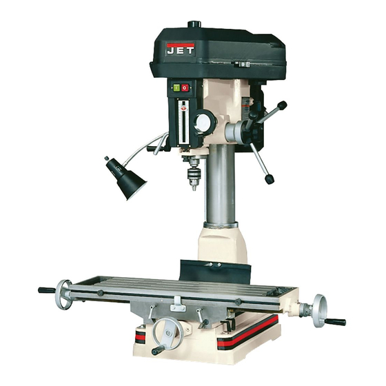
- Page 1 .JET EQUIPMENT & TOOLS OPERATOR'S MANUAL JMD Series Mill I Drills (JMD-18 shown with optional CS-18 stand) JET EQUIPMENT & TOOLS, INC. P.O. BOX 1349 253-351-6000 Fax 253-939-8001 Auburn, WA 98071-1349 A WMH - Walter Meier Holding Company 09/'01 No. M.350019...
- Page 2 JET's expense, but if it is determined there is no defect, or that the defect resulted from causes not within the scope of JET's warranty, then the user must bear the cost of storing and returning the product. This warranty gives you specific legal rights, and you have other rights, which vary, from state to state.
-
Page 3: Warning
Turn power off. Never leave a tool WARNING unattended. Do not leave a tool until it comes to a complete stop. Read and understand the entire contents of Keep work area clean. Cluttered areas and this manual before attempting set-up or benches invite accidents. -
Page 4: Table Of Contents
JMD-15 350017 JMD-18 350018 JMD-18PFN 350020 Drilling Capacity: JMD-15 1" JMD-18/18PFN 1-1/4" Face Mill Capacity: JMD-15 """"""""""""""""""""""""""""""'''''''''''''''''''''''''''''''''''''''''''''''''''''''''''''''' 2-1/2" 3" JMD-18/18PFN """"""""""""""""""""'"'''''''''''''''''''''''''''''''''''''''''''''''''''''''' End Mill Capacity: JMD-15 1/2" JMD-18/18PFN """""""""""'"'''''''''''''''''''''''''''''''''''''''''''''''''''''' """'''''''''''''''''''''''''''''' .3/4" Swing: All Models 15-7/8" Maximum Distance Spindle to Table: 15"... -
Page 5: Table Of Contents
""""'" 800 Lbs. The specifications in this manual are given as general information and are not binding. JET Equipment and Tools reserves the right to effect, at any time and without prior notice, changes or alterations to parts, fittings, and accessory equipment deemed necessary for any reason whatsoever. -
Page 6: Table Of Contents
3/8"x1" Hex Socket Cap Screw 3/8" Washer Crank Body Crank Handle 3mm Hex Wrench 5mm Hex Wrench 23mm Hex Socket Wrench (JMD-18/18PFN) Hand Wheels w/ Handles Can Touch-Up Paint Operator's Manual Warranty Card Unpacking and Clean-up 1. Finish removing the crate from the mill/drill. -
Page 7: Installation
Assembly 1. Screw plastic knob (A, Fig. 1) onto handle shaft (B, Fig. 1). Screw handle shaft into downfeed hub (C, Fig. 1) and tighten. Flat spot on shaft accommodates a combination or adjustable wrench. Note: Handle shafts are already installed into hub on JMD-18PFN. -
Page 8: Electrical Connections
the mill/drill is level after the fastening hardware has been tightened. Lubrication Lubricate all ball oilers on the machine once daily with 20W machine oil. The spindle bearings are permanently sealed and require no lubrication. Electrical Connections CURRENT CARRYING PRONGS Before making any electrical connections, make sure the power source available is compatible with the GROUND... -
Page 9: Controls
(E, Fig. 6) are located on the right side under the table. Turn clockwise to lock. Depth Stop (A, Fig. 7 - JMD-18) or (A, Fig. 8 - JMD- 15) -located on the left side (JMD-15) or center (JMD-18) of the quill assembly. -
Page 10: Crank Handle
Motor Mount Lock Lever (A, Fig. 9) - located on the right side of the head casting. Locks and unlocks the motor mounting plate. Loosen to tension v-belts and then tighten. Head Pivot Lock (8, Fig. 9) - located on the right rear of the head casting. -
Page 11: Operation
Operation Changing Spindle Speeds 1. Disconnect the machine from the power source. 2. Release two catches on the belt cover and open. 3. Loosen the motor mount lock lever (A, Fig, 9) and pull the motor toward the head casting to release tension on the v-belts. -
Page 12: Gib Adjustment
4. Loosen the drawbar approximately three to four full turns. 5. Tap the drawbar head with a rubber mallet to dislodge the arbor. 6. Grasp the arbor with one hand while loosening the draw bar with the other. Continue to loosen the drawbar until the arbor can be withdrawn from the spindle. -
Page 13: Power Feed Operation
Power Feed Operation (JMD-18PFN only) 1. Set the power feed speed range dial (A, Fig. 14) to the desired rate. 2. Set the depth stop to the desired setting by lowering the quill to the desired depth and holding in place. Turn the collar (8, Fig. 14) counter-clockwise until zero is indicated and then tighten the lock handle (C, Fig. - Page 14 CJ'I :::I: ..I\.) » o<: 8611 20-L.I.
- Page 15 Parts List for the JMD-15 Mill/Drill Head Assembly Index Part Size Description Qty. JMD15-001 """""'"'''''''''' Arbor Bolt (drawbar) JMD15-002 """""""'"'''''' Spindle Lotk Nut JMD15-003 Spindle Pulley JMD15-005 Outer Bearing Plate JMD15-006 Spindle Taper Sleeve BB-6007ZZ ... Ball Bearing ...'" """"" JMD15-008.
- Page 16 JMD15-063 Pin """"""""""""""""''''''''''''''''''''''''''''''''', JMD15-066 """""""" Motor Mount ""'"'''''''' """"" 67 ... JMD15-067 . Motor "'''''''''''''''''''''''''''''''''' JMD15-067A ""'"'' Capacitor (Not Shown) JMD15-069 Belt Cover (ser.#8040225 and lower) JMD15-069P Belt Cover (ser.#8040226 and higher) 69-1 JMD15-069A Upper Belt Cover Cap (ser.#8040225 and lower) JMD15-069P1 Upper Belt Cover Cap (ser.#8040226 and higher) 69-2...
- Page 17 TS-0680061 Washer JMD15-152 RoundHead Screw 1/4x3/8 TS-0271061 Screw 3/8x5/8 TS-0561071 Hex NuL TS-0680031 Washer 5/16 TS-0051051 Hex Head BoiL 5/16x1 TS-0060011 Hex Head Bolt 3/8x1/2 TS-0561021 Hex NuL 5/16 JMD18-159 7x7x40 TS-0051071 Hex Head BoiL 5/16x1-1/2 TS-0680031 Washer 5/16 JMD15-164 RoundHeadScrew M3x15 TS-0680011...
- Page 18 JMD-15 Table, Base, and Column Assembly ClIO...
- Page 19 JMD-15 Table, Base, and Column Assembly JMD18-201 Table Hand Wheel 1-1 . JMD18-201-1 Bolt JMD18-201-2 Handle JMD18-201-3 JMD18-202 Dial Clutch .JMD18-202-1 Graduated Dial BB-51103 Thrust Bearing ... JMD15-204 Square Flange ...JMD18-204-2 Rivet JMD15-205 Table Screw ...JMD15-206.. Base ... 1 .JMD15-207 Gib Strip JMD15-208 Column Base """"""'"''''''''''''''''''''''''''''''''''''...
- Page 20 * Contents of the Accessory Package (JMD15-AP): ..JMD15-020 ..Cutter Arbor .., """'" '" .JMD15-039 .." Handle """"""""""""""""""""""'''''''''''''''' JMD 15-040 Knob Chuck JMD15-087 Drill ...JMD15-086 Cutter '''' """""""""""'"'' """"""'" .365534 Angle Vise "'"'''''''''''''''''''''' """'"'''''''' """"'" ""'"'''''''' ...1 ..JMD15-022 Handle '''''''''''''''''' .JMD15-201 """"""'"''''''''...
- Page 21 f:>" ",~, ~~33 11 63 ..- ..""D ..» (II -<...
- Page 22 Parts List for the JMD-18/18PFN Mill/Drill Head Assembly Index Part Size Description Qty. .JMD18-001 Draw Bar JMD18-002 Spindle Lock Nut(S/N 8050816 and lower) JMD18-002A Spindle Lock Nut(S/N 8050817 and higher)... JMD18-003 " Spindle Pulley (SIN 9041552 and lower) JMD18-003A Spindle Pulley (SIN 9051553 and higher) JMD18-005 "...
- Page 23 JMD18-056 Switch (S/N:205088 and lower) """"''''''''''''''''''''''''''''''''''''''. JMD18-056A Switch (Between S/N:205089 and S/N:xxx2331) JMD18-056AN Switch (S/N:0062332 and higher) JMD18-057 Spindle Speed Chart (SIN 9041552 and lower) JMD18-057A Spindle Speed Chart (SIN 9051553 and higher) .""" .JMD18-058 Handle Crank 59 . JMD18-059..Worm Shaft 60 ..
- Page 24 TS-0050091 Hex Head BoiL 1/4"x2" TS-0561 011 """"""""""" Hex Nut """""""" 114" JMD18-136 Spring Pin (re :JMD18-095) .JMD18-137 '"'''''''''''''''''''' Lock Washer .JMD18-139 """"""""""'" Round Head Screw 3/16"x3/4" .JMD18-140 """""'"'''' Spring Pin '"'''''''''''''''''''''''''' ,.TS-0561 031 Hex Nut 3/8" 7x7x20mm 142 .. JMD18-142..
- Page 25 JMD-18/18PFN Table, Base, and Column Assembly ..
- Page 26 JMD-18/18PFN Table, Base, and Column Assembly JMD18-201 Table Hand Wheel ..JMD18-201-1 Bolt JMD18-201-2 Handle ...3 .JMD18-201-3 Nut..JMD18-202... Dial Clutch JMD18-202-1 Graduated Ring BB-51103 Thrust Bearing JMD18-204 Square Flange JMD18-204-2 ... Rivet JMD18-205 Cross Feed Screw JMD18-206 Base (wi JMD18-216) ..JMD18-207...
- Page 27 * Contents of the Accessory Package: ...JMD18-020 Cutter Arbor .JMD18-022 Handle .JMD18-039 Handle Rod ..JMD18-040 Knob .JMD18-050 Lock Handle. .561704 Drill Chuck ..JMD18-086 Cutter JMD18-021 Chuck Arbor 365534 Angle Vise ..JMD18-058... Handle Crank JMD18-201 Wheel TS-152704 Hex Wrench TS-152705 Hex Wrench TS-152706 Hex Wrench TS-0209051...
- Page 28 Qc.. Q.s:: (1)0 ~.=... CD" (I)." ia' " CDCD 0... ""'" I\,) UlCD UlQ. Q.CD CD'<...
- Page 29 Parts List for the JMD-18PFN Power Feed Assembly Old Style Serial # 9041552 and Lower Index Part Size Description Qty. Main Pulley.. .290111 " "'" JMD18PFN-249 Set Screw 1/4x3/8 JMD18PFN-250 Flat Head Screw 3/16x3/8 Gear Box ..291 001..291006 Worm Shaft 290110...
- Page 30 ..JMD18PFN-295 "'"'''''''''' ... M8 """'''''' 296..JMD18PFN-296 Handle """""""""'"'''''''''''''''''''' ..""""""" .., JMD18PFN-297 Handle Bar Screw ..291 009 Gear Shaft .."""""" ..2450019 Speed DiaT""""""""""""""''''''''''''''''''''''"" JMD18PFN-303 Round Head Screw M4x25 JMD18PFN-304 Speed Scale .2450016 Position Screw """"""""'''''''''''''''''''''''' JMD18PFN-307 "'''''''''''''' Steel...
- Page 31 248~ ~249 -01:) CD." cn." .> -. ." !2.0 <DCD e... <II." <II CD <IIQ. 316~/3_20 W» 1»(1) =(1) Q.CD :1:3 -. 0- ='-< ---"'" 376- 294378...
- Page 32 Parts List for the JMD-18PFN Power Feed Assembly New Style Serial # 9051553 and Higher Part Index Description Size Qty. 290111 Main Pulley ..JMD18PFN-249 Set Screw ""'" """" ... """""" 1/4"x3/8" JMD18PFN-250 Flat Head Screw 3/16"x3/8" .290110 Sub-Pulley "'''''''''''''''''''' ""'"'''''' JM'D18PFN-255 C-Ring BB-600322 """"""""""'"...
- Page 33 .2450032A Scale Base 2450038 Knob wi Shaft JMD18PFN-350 Hex Socket Cap Screw 5/16"x3-112" ..290089 Spring JMD18PFN-352 Steel Ball .2450079 Speed Lever " JMD18PFN-354 Speed Scale ...1 355 ., CA6003ZZ Bearing .245OO82A " Change Gear Lever """""""'''''''' 2450084B TorsionalSpring " ..JMD18PFN-358 5x5x32 2450083A Stop...
-
Page 34: Electrical Schematic
Electrical Schematic - JMD-15 (115V) START <{ WilD JMD-15 (230V) CAPAaT~ START <{ WI;E STOP... - Page 35 Electrical Schematic - JMD-18/18PFN (230V) BLACK START « ::!Iffi...
Need help?
Do you have a question about the JMD-18 and is the answer not in the manual?
Questions and answers